

OPERATING AND
INSTALLATION
DIFFERENTIAL TEMPERATURE CONTROLLER FOR ROOM/SPACE HEATING
SYSTEMS AND DOMESTIC HOT WATER SYSTEMS HANDLING SOLID FUEL
HEAT SOURCES, NAMELY WOOD LOG AND PELLET STOVES
INSTRUCTIONS
emz - THE SMILING COMPANY

These Assembly and Operating Instructions are an integral part of the product.
› Read Assembly and Operating Instructions carefully before using the product.
› Keep them in a safe place during the product‘s service life.
Original version in English language ©emz 2016 - Subject to modifications.
The contents and representations of these Assembly and Operating Instructions are the intellectual
property of emz-Hanauer GmbH & Co.KGaA.
Non-authorized disclosure, reproduction, divulgation or editing of this documentation, as well as
exploitation, utilization or publication, are prohibited.
The rights to the word and design marks ›emz - smart solutions‹ and ›smart Stove‹ are the exclusive
property of emz-Hanauer GmbH & Co.KGaA.
The rights to any cited brands, names or logos are the property of their appropriate developers / of
the licensees in question.

TABLE OF CONTENTS
Table of contents
Table of contents................................................................................................................................ 3
Important information ......................................................................................................................... 7
Safety information ......................................................................................................................... 7
Conditions of use ..........................................................................................................................7
Intended use .................................................................................................................................8
Description ......................................................................................................................................... 9
Scope of supplies.......................................................................................................................... 9
Mounting and connection.............................................................................................................. 9
Data interfaces............................................................................................................................ 10
Data logging................................................................................................................................ 11
Operation of the controller................................................................................................................ 12
Control elements......................................................................................................................... 12
Display ........................................................................................................................................13
Information screen ................................................................................................................. 13
Operation mode ..................................................................................................................... 13
Communication screen .......................................................................................................... 14
Hydraulic systems ............................................................................................................................ 16
Hydraulic symbols....................................................................................................................... 16
Hydraulic system 1: Wood log stove........................................................................................... 17
Connection of hydraulic system 1 .......................................................................................... 17
Hydraulic system 2: Wood log stove, tank with zone valve ........................................................ 18
Connection of hydraulic system 2 .......................................................................................... 18
Hydraulic system 3: Wood log stove, tank with charging zones,
external domestic hot-water tank ................................................................................................19
Connection of hydraulic system 3 .......................................................................................... 19
Hydraulic system 4: Pellet stove with combination tank ............................................................. 20
Connection of hydraulic system 4 .......................................................................................... 20
Hydraulic system 5: Pellet stove ................................................................................................. 21
Connection of hydraulic system 5 .......................................................................................... 21
Hydraulic system 6: Pellet stove with external additional heating............................................... 22
Connection of hydraulic system 6 .......................................................................................... 22
Hydraulic system 7: Pellet stove, tank with charging zones, external domestic hot-water tank . 23
Connection of hydraulic system 7 .......................................................................................... 23
Functions for stove control ............................................................................................................... 24
Fire detection ..............................................................................................................................24
Fire detection with pellet stove............................................................................................... 24
Dynamic pump delay (DPD.........................................................................................................24
Dynamic pump control ................................................................................................................24
Overtemperature protection ........................................................................................................ 25
smart Stove - 0142 - 42WMSUGAT2-C 3

TABLE OF CONTENTS
Antifreeze protection ...................................................................................................................26
Anti-legionella function ................................................................................................................26
Additional heating........................................................................................................................ 26
Request for heat.......................................................................................................................... 27
Request for heat with wood log stove .................................................................................... 27
Request for heat with pellet stove .......................................................................................... 27
Thermostat functions........................................................................................................................28
Temperature thermostat “Heating”.............................................................................................. 28
Temperature thermostat “Cooling” .............................................................................................. 28
Timer function .............................................................................................................................28
Timer thermostat .........................................................................................................................29
Temperature comparator ............................................................................................................29
Temperature thermostat “Window” ............................................................................................. 29
Automatic operation .........................................................................................................................30
Settings during operation .................................................................................................................31
Menu structure ............................................................................................................................31
Main menu ..................................................................................................................................32
Evaluation ..............................................................................................................................32
Settings ..................................................................................................................................34
Basic functions....................................................................................................................... 36
Monitoring ..............................................................................................................................38
Login ......................................................................................................................................38
About......................................................................................................................................39
System ...................................................................................................................................39
Mounting........................................................................................................................................... 40
Dimensions .................................................................................................................................40
Opening the terminal cover .........................................................................................................40
Wall-mounting .............................................................................................................................41
Designation of the components...................................................................................................43
Electrical connection ........................................................................................................................44
Terminals ....................................................................................................................................44
Cable preparing........................................................................................................................... 45
Connection of a zone valve to RO1/RO2 ....................................................................................46
Connection of a zone valve to REL............................................................................................. 46
Connection of a pump to REL .....................................................................................................46
Blocking connection of a pump to REL .......................................................................................47
Connection of a boiler to REL .....................................................................................................47
Connection of an external heat source to REL ........................................................................... 47
Blocking connection of an external heat source to REL.............................................................. 48
Blocking connection of a pump to RO2....................................................................................... 48
Connection for request for heat to RO1 ......................................................................................48
4 smart Stove - 0142 - 42WMSUGAT2-C

TABLE OF CONTENTS
High-efficiency pump .................................................................................................................. 48
Commissioning................................................................................................................................. 50
Basic settings.............................................................................................................................. 50
Load an existing configuration ....................................................................................................51
Choose system ...........................................................................................................................51
Checklist ..................................................................................................................................... 51
Settings in the professional mode .................................................................................................... 54
Login ...........................................................................................................................................54
Main menu .................................................................................................................................. 54
Evaluation .............................................................................................................................. 55
Settings.................................................................................................................................. 55
Basic functions....................................................................................................................... 55
Protective functions................................................................................................................ 63
Monitoring .............................................................................................................................. 64
Login ...................................................................................................................................... 65
Manual mode ......................................................................................................................... 65
Firmware update .................................................................................................................... 65
Summary of parameters in ›Basic functions‹ .............................................................................. 67
Malfunction....................................................................................................................................... 73
Sensor monitoring....................................................................................................................... 73
Service Wizard............................................................................................................................ 74
Example for protective function.............................................................................................. 74
Example for malfunction ........................................................................................................ 74
Replacement of fuse ........................................................................................................................ 78
Technical data.................................................................................................................................. 80
Differential temperature controller smart Stove .......................................................................... 80
Connection to power supply........................................................................................................ 80
Max. cross sections to be connected.......................................................................................... 80
Interfaces TS1 / TS2 / TS3 / TS4 / TS5 / TS6............................................................................. 80
Interface TS7 / TS8..................................................................................................................... 81
Triac outputs RO1 / RO2 ............................................................................................................ 81
Switching output REL: change-over contact ............................................................................... 81
Interface for analogue Vortex flow sensors................................................................................. 81
Disassembly/disposal....................................................................................................................... 82
Warranty and liability........................................................................................................................ 83
Commissioning report ...................................................................................................................... 84
Service request ................................................................................................................................ 85
CE declaration of conformity ............................................................................................................ 86
smart Stove - 0142 - 42WMSUGAT2-C 5

TABLE OF CONTENTS
Index ................................................................................................................................................ 87
6 smart Stove - 0142 - 42WMSUGAT2-C
IMPORTANT INFORMATION
Important information
Safety information
The Assembly and Operating Instructions indicate possible hazards:
DANGER indicates an almost certain danger of serious personal injury or death.
WARNING indicates a possible danger of serious personal injury.
CAUTION indicates a possible danger of slight personal injury.
NOTICE indicates a possible danger of damage to the equipment.
When handling the differential temperature controller smart Stove and the entire plant, please make
sure that the safety provisions in the Operating and Installation Instructions are complied with!
Conditions of use
These instructions describe installation, commissioning, operation, repair, and disassembly of the
differential temperature controller smart Stove for solid fuel heat sources, namely wood log and pel
let stoves.
For operation of the entire plant, the technical documentation of all the components used such as
stove, boiler, tank, pumps, mixers, and valves, etc. must be complied with.
-
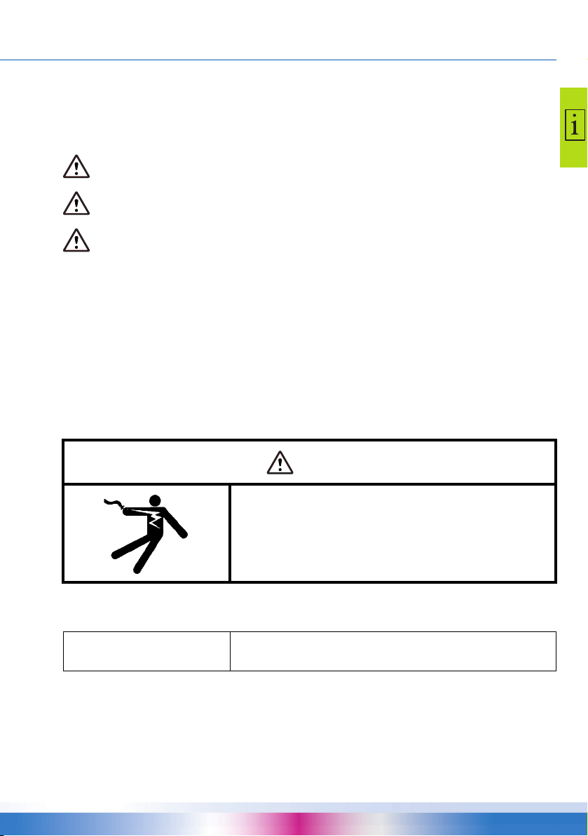
DANGER
Assembly, connection, commissioning, repair, or disassembly
Lethal danger due to electrocution!
Whenever work is performed on the open terminal cover, all
poles of the power supply must be disconnected reliably and
protected against being switched on again!
The controller is handled by the operator of the entire thermal plant, i. e. as a rule by technical nonexperts.
NOTICE
Make sure not to use the controller until you have thoroughly read and understood these Assembly
and Operating Instructions and the safety provisions. Comply with all safety provisions and involve a
specialist in case of doubt.
The controller by no means replaces the safety components
required under plant engineering aspects!
smart Stove - 0142 - 42WMSUGAT2-C 7

IMPORTANT INFORMATION
NOTICE
Keep these Assembly and Operating Instructions and all reference documents so that they are
available if required.
When relocating or when selling the device, hand the documents over to your successor.
NOTICE
NOTICE
Intended use
The differential temperature controller smart Stove may be used exclusively for controlling heating
and water temperatures for use with hydrophilic wood log and pellet stoves in combination with one
or more buffer tanks.
It must be operated within the scope of all the specifications described.
Installation and set-up of the controller may only be performed by specialists.
The installer must have read and understood the operating manual. The installer explains all the relevant functions to the operator.
For operation, it is essential that the housing is closed and free of damage.
The installer installing the controller must inform the plant
operator about operation, functioning and the method of action
of the smart Stove!
The device in operation may only be made accessible to adults
disposing of appropriate knowledge and experience!
Make sure that only a dry or slightly moistened cloth is used for
cleaning and servicing of the housing, the control elements
and the display.
The surfaces must never get into contact with cleaning products or solvents - mat, brittle or slightly dissolved plastic parts
must be replaced immediately!
A device with damaged housing must not be operated!
8 smart Stove - 0142 - 42WMSUGAT2-C
DESCRIPTION
Description
The differential temperature controller smart Stove is an independent electronic controller for controlling heating and water temperatures for use with hydrophilic wood log and pellet stoves in combination with one or more buffer tanks.
The controller is equipped with a robust three-part plastic housing which can only be opened by
means of tools (screw driver PH2).
Operation is effected by means of only two control elements; indications appear against a backlit
colour display.
Scope of supplies
• Differential temperature controller smart Stove
• Operating Instructions
Mounting and connection
Before connection of the electrical system, the controller must be mounted firmly to a perpendicular,
robust surface (wall), see
For its own supply and the supply of the outputs, the controller must be connected to an electrical
energy supply system in accordance with the technical data, see
“Mounting” on page 40.
“Electrical connection” on page 44.
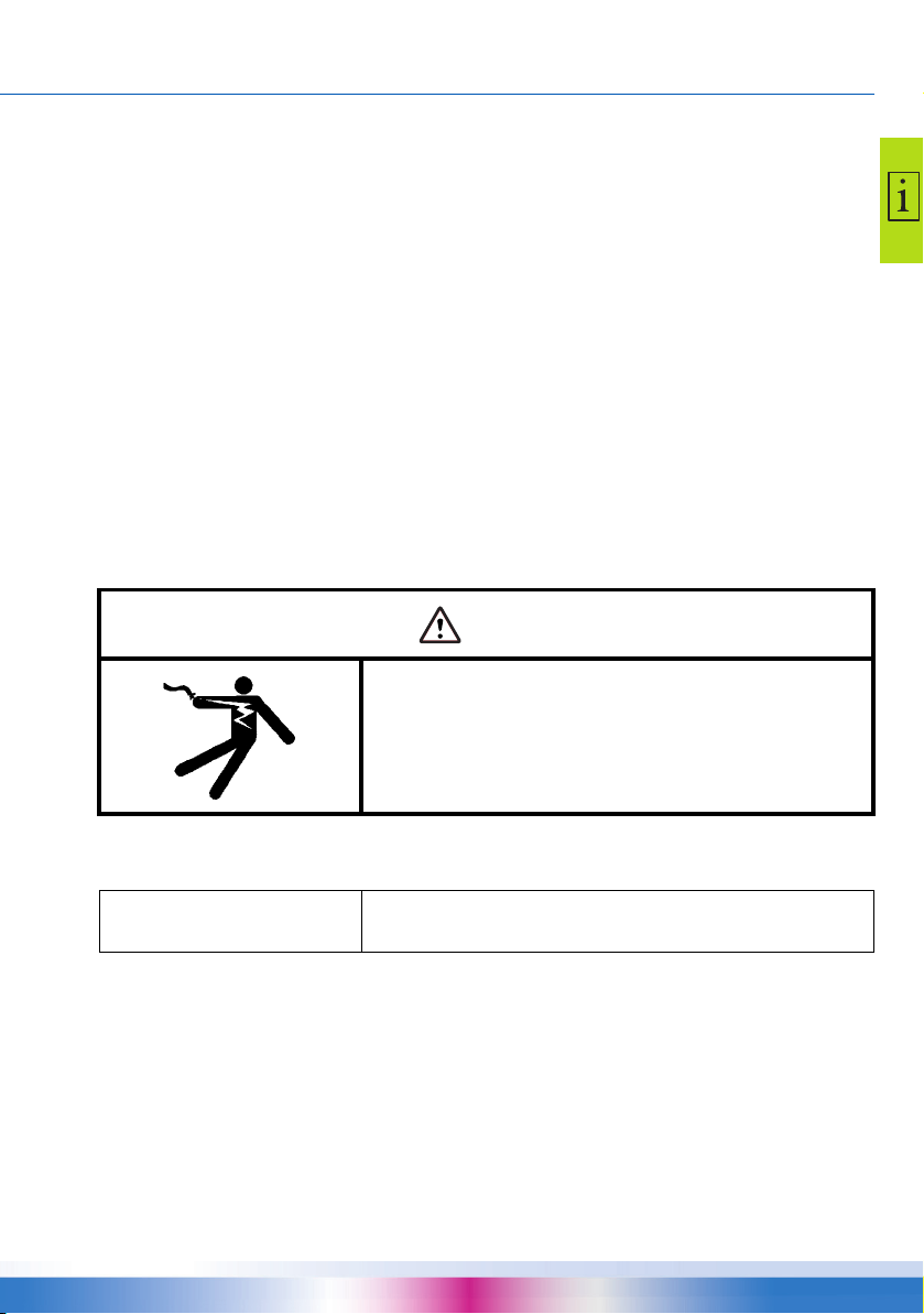
DANGER
Loose installation or connection
Lethal danger due to electrocution!
Whenever work is performed on the open terminal cover, all
poles of the power supply must be disconnected reliably and
protected against being switched on again!
Assembly, connection, commissioning, repair and disassembly of the controller are only admissible
in a specialist workshop.
NOTICE
Each temperature sensor has two connectors which are equivalent, i. e. interchangeable. Thus,
polarity reversal is not an issue.
The sensor lines can be extended up to a length of 100 m, to this effect, a cable cross section of
2
x 1.5 mm2 is recommended.
To ensure correct operation, temperature sensors type Pt 1000
must be used - the sensor design does not affect function.
smart Stove - 0142 - 42WMSUGAT2-C 9
DESCRIPTION
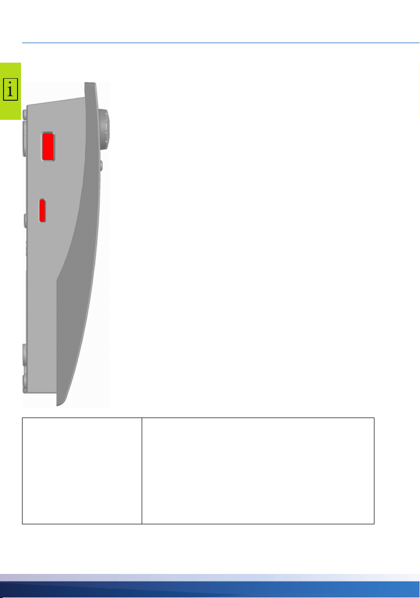
USB port
Micro SD
card
Data interfaces
The controller has the following data interfaces:
The cut-outs at the left of the housing base accommodate a
USB port as well as a slot for a storage medium (Micro SD
card).
These interfaces are used, for example, for reading of error
messages or log data or loading of software updates.
The USB port provides access to the Micro SD card.
Only SD cards approved by the manufacturer must be used.
The controller automatically detects the Micro SD card.
Prior to removing the Micro SD card ›Rem.SD card safely‹
must be selected in ›1.2 Settings‹, otherwise data loss may
occur.
Since the controller can only read formatted SD cards, the
Micro SD card must be formatted with a PC.
NOTICE
Micro SD cards recommended by the manufacturer:
Transcend® 2GB Product-No. TS2GUSDC
Transcend® 4GB HC
Transcend® 1GB
Verbatim 2GB
PNY 2GB
hp 2GB
SanDisk 2GB
10 smart Stove - 0142 - 42WMSUGAT2-C

DESCRIPTION
Data logging
When an optional Micro SD card is inserted in the device, data logging is always active on the controller.
Data is written to the LOGFILES directory.
The recording is performed in CSV format, so that the files can be easily imported into calculation or
presentation programs. A new file will be created for each day. The interval for data recording is
10
seconds.
The following values will be recorded and each row contains the following information:
• Time of the day (hours, minutes, seconds)
• Current temperature values of TS1 – TS6
• Output states (speed) of RO1, RO2, REL, TS7, TS8
• Lock-states (safety functions)
• Error codes
In the header of each file the date, the controller ID, as well as the column label of the recording data
is applied.
smart Stove - 0142 - 42WMSUGAT2-C 11
OPERATION OF THE CONTROLLER
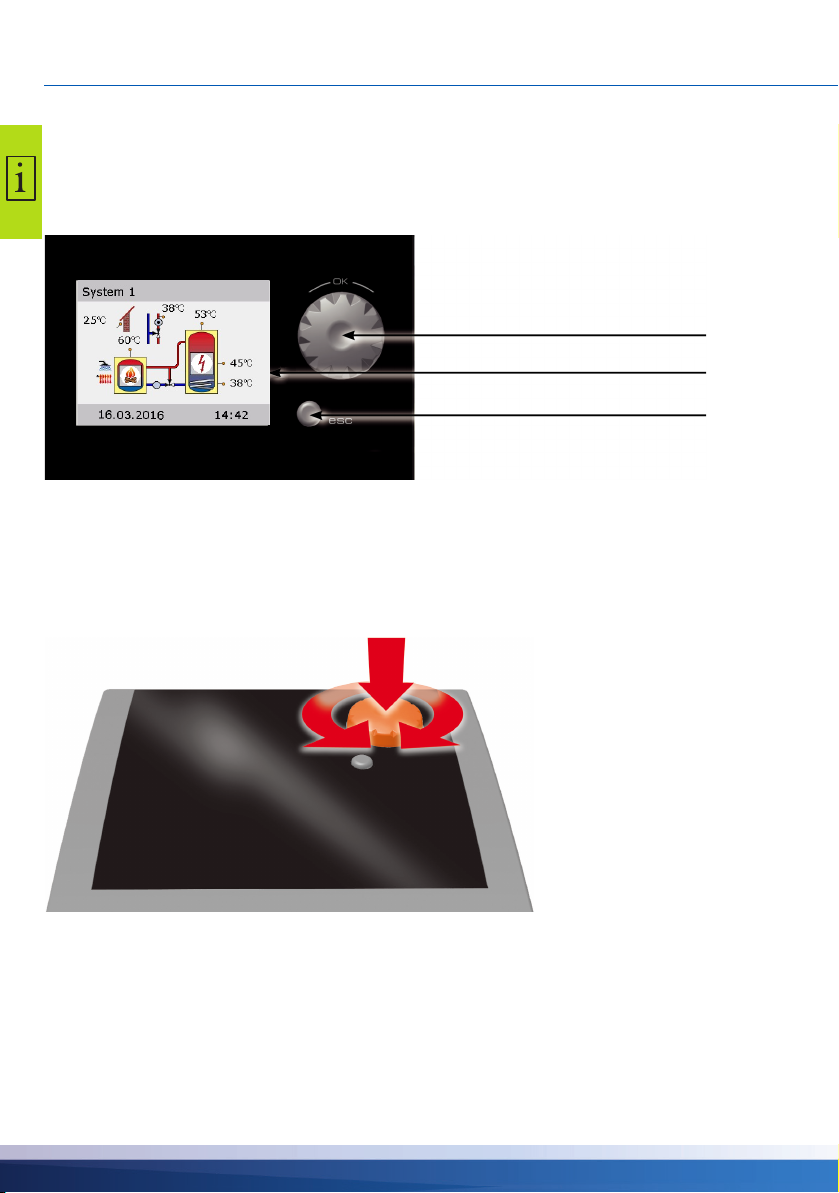
Knob with OK button
Display
esc button
Operation of the controller
Control elements
The entire set-up and operation of the differential temperature controller smart Stove is effected via
only two control elements on the device front.
All settings and interrogations are effected via the knob and the esc button.
• To find a required menu item, turn the knob to scroll through the menu - the selectable option
appears on a coloured background on the display.
• To confirm the selected menu item, press the knob (“OK”).
An appropriate submenu is called up, or selection is activated.
Knob
• Press the esc button to make the menu return by one level from any subitem.
If no input is made within the preset time (30-255 s), the controller returns automatically to the initial
level.
12 smart Stove - 0142 - 42WMSUGAT2-C
OPERATION OF THE CONTROLLER
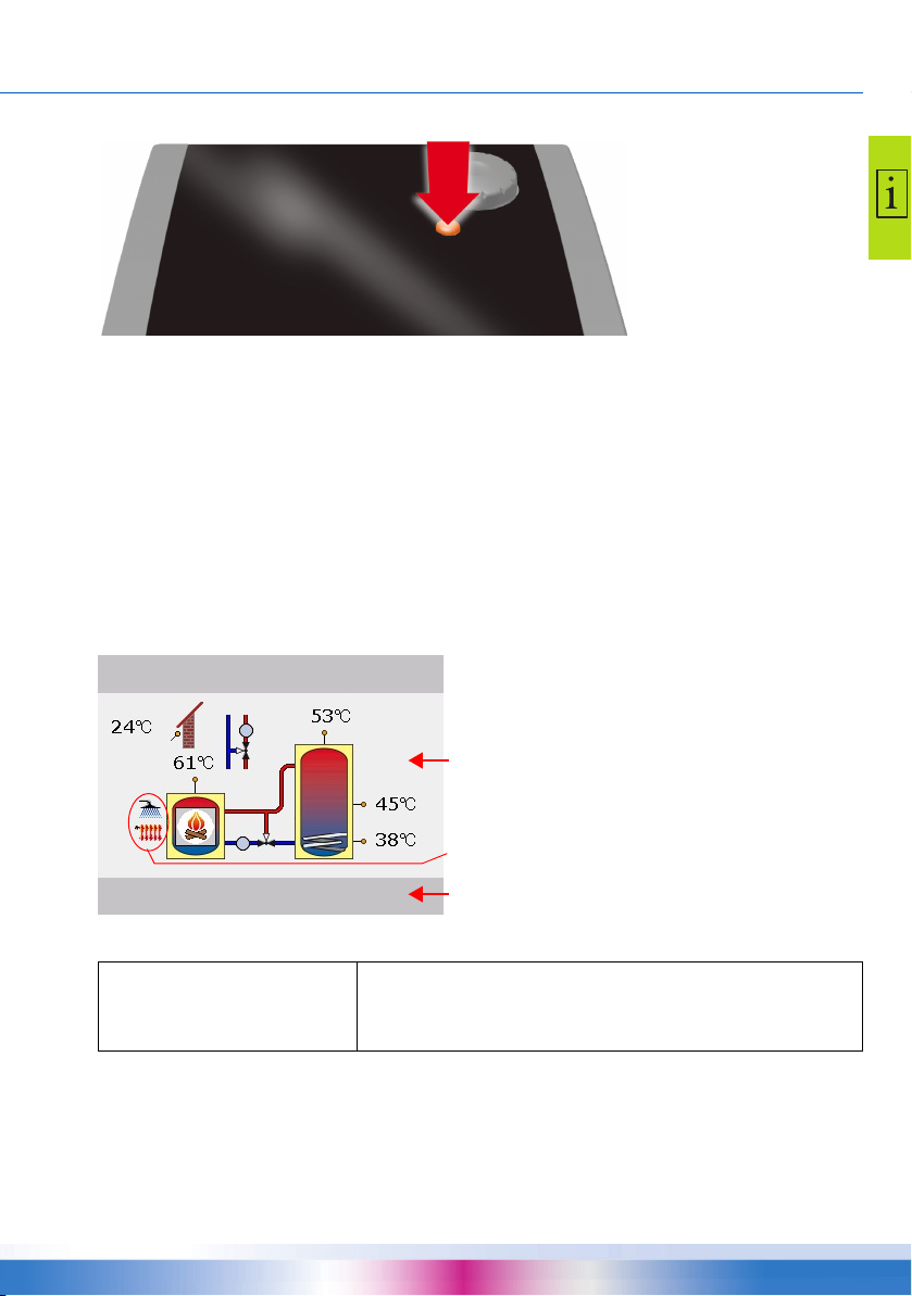
Active system with current temperatures
Date and time
System 1
17.03.2016 10:35
Indication of demand for domestic hot water and/or
space heating
esc button
Display
For indication of the operating mode and for communication in case of set-up, malfunction, modification and evaluation, the differential temperature controller smart Stove is equipped with a coloured
full graphics display which is permanently backlit.
The display is active as long as there is supply voltage on the controller.
After a preset time (30 - 255 s), backlighting is dimmed to approx. 10%.
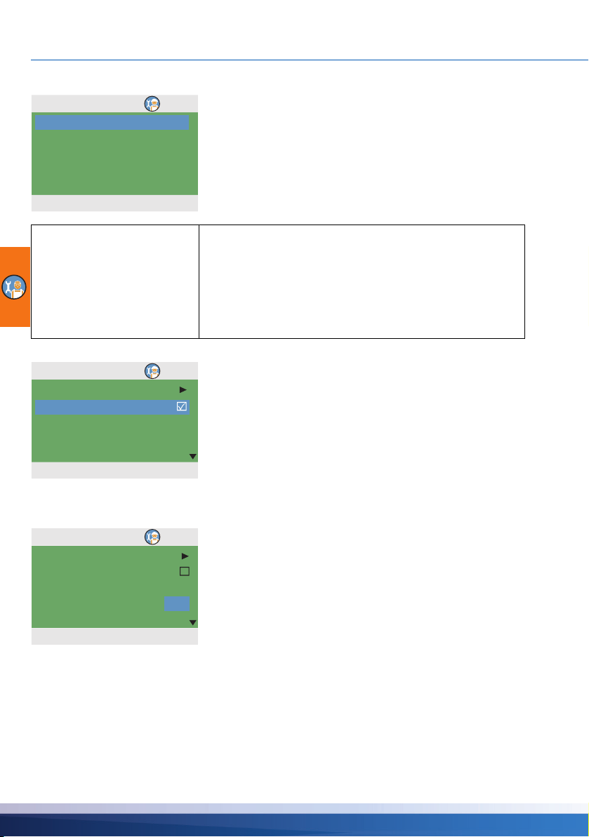
Information screen
During normal operation, the information screen is displayed. It shows the active system, the system
state, the current temperatures, and it animates active hydraulic components.
(Example)
NOTICE
Operation mode
When you turn the knob while the information screen is shown, the ›Operation mode‹ screen will be
displayed.
The real-time clock has a power reserve of 8 hours minimum.
If the controller is disconnected from power supply for a longer
time, date and time must be set, see
smart Stove - 0142 - 42WMSUGAT2-C 13
“Settings” on page 34.
OPERATION OF THE CONTROLLER
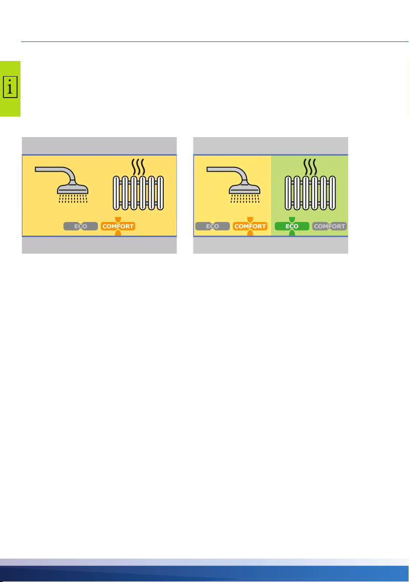
Operation mode
17.03.2016 10:35
Operation mode
17.03.2016 10:35
The following operation modes are available:
• Comfort mode: Provides more stored energy to be used over time.
• Economy mode: Conserves energy and stores only a minimum.
The setting Eco or Comfort to select depends on your requirements, season of year and the heating
installation. When changing from Eco to Comfort, the controller will use temperature sensors in a dif
ferent positions. This determines when the controller will stop a request for heat.
-
• Common mode: Eco/Comfort mode is the
same for space heating and domestic hot
water.
You can change the operation mode by pressing the knob once.
When Separate mode is configured, turning the knob will move the selection between space heating
or domestic hot water.
The Common mode can be activated via ›Common Eco/Comf‹ during commissioning, see
“Checklist” on page 51.
To return to the information screen, press the esc button.
Communication screen
When you press the knob while the information screen is shown, the communication screen will be
displayed. It shows the menu of selectable functions and parameters.
“Menu structure” on page 31
• Separate mode: Eco/Comfort mode can be
individually selected for space heating and
domestic hot water.
14 smart Stove - 0142 - 42WMSUGAT2-C
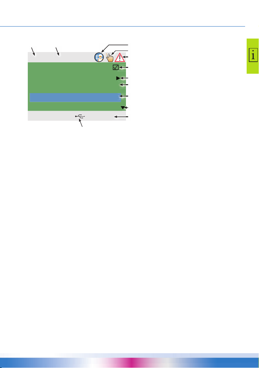
(Example)
Number and name of menu
Professional mode
Manual mode
Message
Check box
Submenu arrow
Selection menu
Active menu item
Scroll arrow
Date and time
1.3.1 Thermostat R...
17.03.2016 10:35
Activation
Start
Timer,thermostat
Sensor TS3
Output RO2
USB connection symbol
To return to the information screen, press the esc button.
OPERATION OF THE CONTROLLER
smart Stove - 0142 - 42WMSUGAT2-C 15
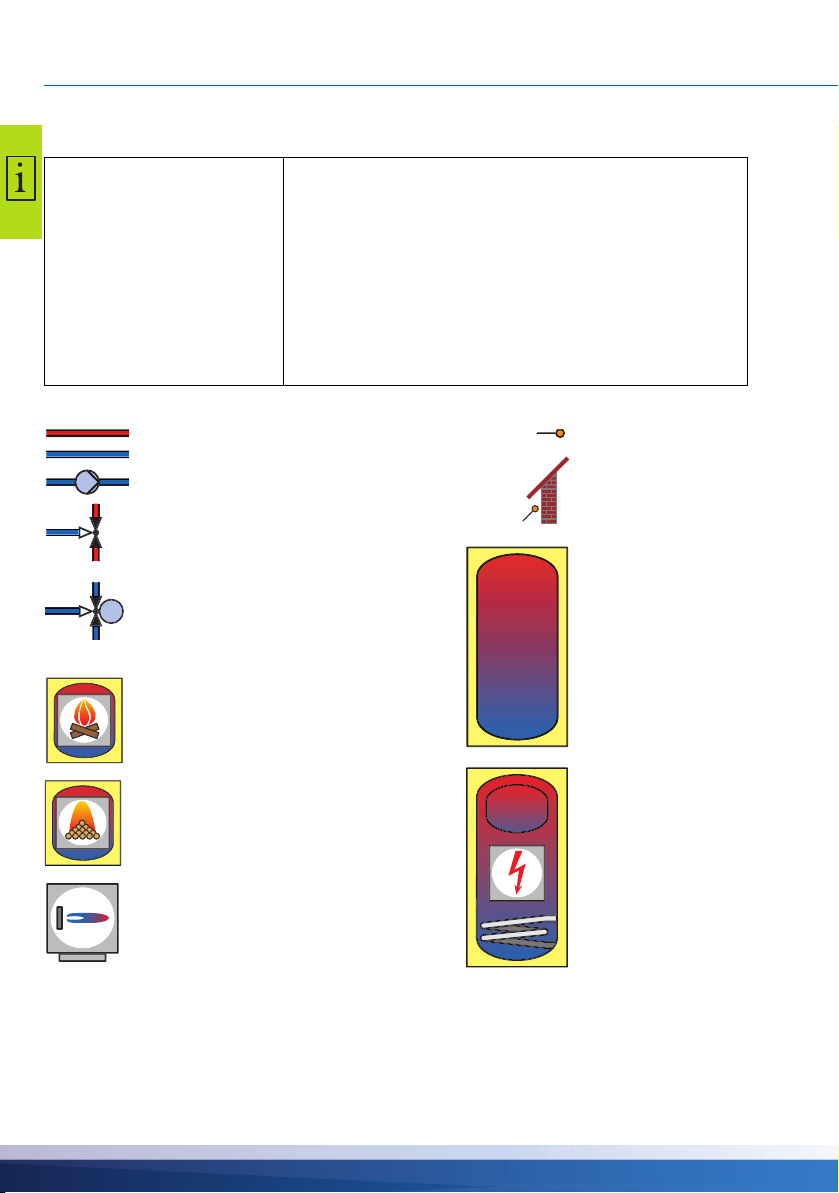
HYDRAULIC SYSTEMS
Supply line
Return line
Pump
Zone valve or mixing valve
(controlled by other plant components)
Wood log stove
Pellet stove
Boiler, e. g. using fossil fuels/solid fuels/
heat pump etc.
Temperature sensor
Outdoor temperature
sensor
Hot-water/buffer tank
without internal
components
Hot-water/buffer tank
with:
• Additional domestic
hot water tank
• Additional heating,
e.g. electric
• Heat exchanger
• Solar coil
Zone valve controlled by smart Stove
Hydraulic systems
NOTICE
Hydraulic symbols
Define structure and design of the plant already when planning
the entire wood log or pellet stove thermal system and align
the design with the one of the hydraulic systems of the control
ler!
If you want to complete an existing system or replace the existing controller, please make sure that smart Stove is compatible
with the existing configuration!
The sensors are connected to TS1 to TS6, pumps and valves
are connected to RO1/RO2/REL/TS7/TS8 - The interfaces are
assigned to the functions in question on commissioning.
-
16 smart Stove - 0142 - 42WMSUGAT2-C
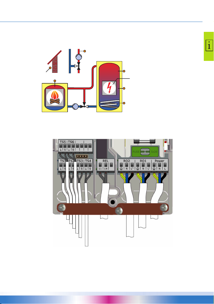
Hydraulic system 1: Wood log stove
TS6
TS5
RO2
TS1
TS2
TS3
TS4
RO1
REL
Supply line sensor
Outdoor temperature sensor
Power supply (230 V AC)
Charging pump (230 V AC)
Tank sensor, middle
Blocking of space heating pump
(230 V AC), see “Blocking connection of
a pump to RO2” on page 48
Additional heating,
see “Connection of
an external heat
source to REL” on
page 47
Tank sensor, bottom
Stove sensor
Tank sensor, top
Connection of hydraulic system 1
HYDRAULIC SYSTEMS
TS1: Stove sensor
TS2: Tank sensor, top
TS3: Tank sensor, middle
TS4: Tank sensor, bottom
TS5: Supply line sensor
(optional)
TS6: Outdoor temperature
sensor (optional)
RO1: Charging pump
RO2: Blocking of space heating
pump
REL: Additional heating
smart Stove - 0142 - 42WMSUGAT2-C 17

HYDRAULIC SYSTEMS
Tank sensor, top
Power supply (230 V AC)
Charging pump (230 V AC)
Tank sensor, middle
Zone valve (230 V AC), see “Connection
of a zone valve to RO1/RO2” on page 46
Additional heating,
see “Connection of
an external heat
source to REL” on
page 47
Tank sensor, bottom
Stove sensor
Hydraulic system 2: Wood log stove, tank with zone valve
TS1
RO1
Connection of hydraulic system 2
RO2
TS2
TS3
TS4
TS1: Stove sensor
TS2: Tank sensor, top
REL
TS3: Tank sensor, middle
TS4: Tank sensor, bottom
RO1: Charging pump
RO2: Zone valve
REL: Additional heating
18 smart Stove - 0142 - 42WMSUGAT2-C
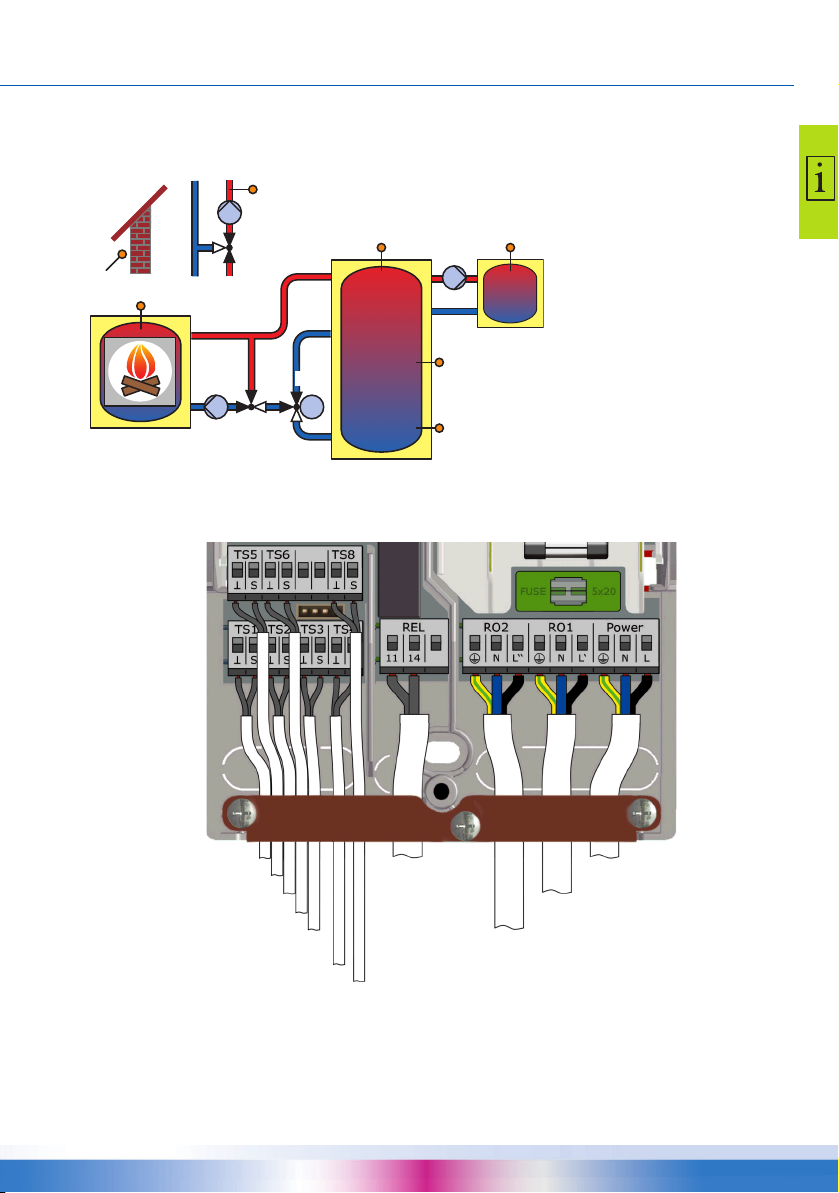
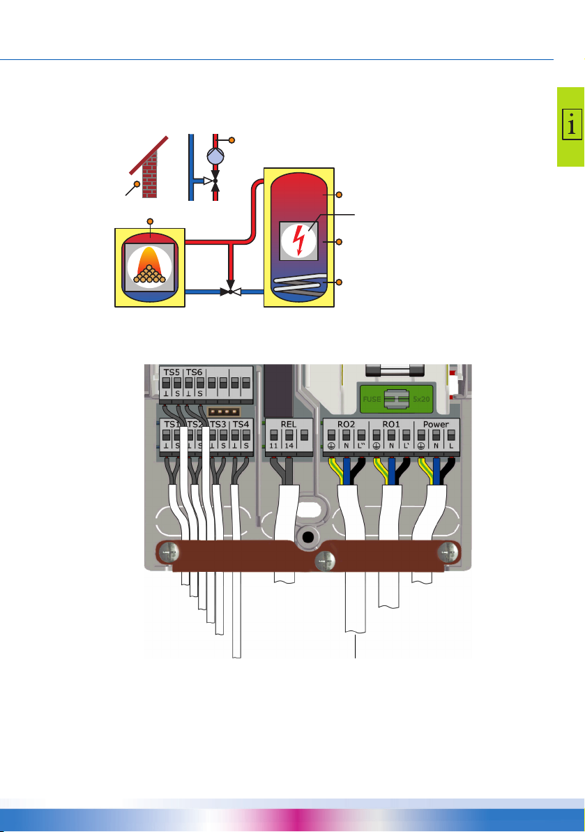
Hydraulic system 3: Wood log stove, tank with charging zones,
TS6
TS6
REL
TS1
TS2
TS3
TS4
RO1
TS5
TS8
RO2
DHW tank sensor
Optional sensor
Power supply (230 V AC)
Charging pump (230 V AC)
Tank sensor, middle
Zone valve (230 V AC), see “Connection
of a zone valve to RO1/RO2” on page 46
Space heating
pump, see
“Blocking con-
nection of a
pump to REL” on
page 47
Domestic hot-water pump
Stove sensor
Tank sensor, top
Tank sensor, bottom
external domestic hot-water tank
TS1: Stove sensor
TS2: Tank sensor, top
TS3: Tank sensor, middle
TS4: Tank sensor, bottom
TS5: Domestic hot-water tank
sensor
TS6: Supply line sensor or outdoor temperature sensor
(optional)
RO1: Charging pump
RO2: Zone valve
REL: Space heating pump
TS8: Domestic hot-water pump
Connection of hydraulic system 3
HYDRAULIC SYSTEMS
smart Stove - 0142 - 42WMSUGAT2-C 19
HYDRAULIC SYSTEMS
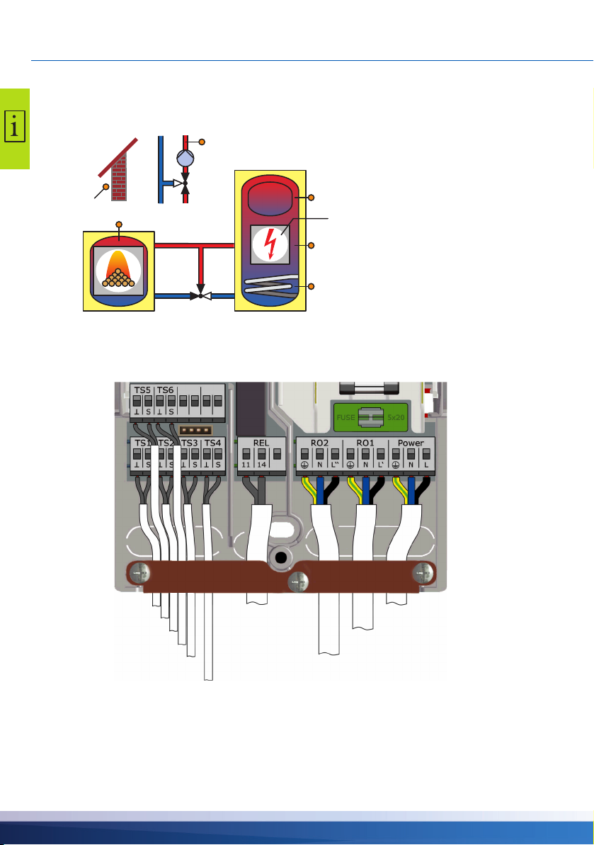
Supply line sensor
Outdoor temperature sensor
Power supply (230 V AC)
Request for heat (230 V AC),
connection according to page 48
Tank sensor, middle
Blocking of space heating pump
(230 V AC), see “Blocking connection of a
pump to RO2” on page 48
Additional heating,
see “Connection of
an external heat
source to REL” on
page 47
Tank sensor, bottom
Stove sensor
Tank sensor, top
Hydraulic system 4: Pellet stove with combination tank
RO2
TS6
TS1
RO1
Connection of hydraulic system 4
TS5
TS2
TS3
TS4
TS1: Stove sensor
TS2: Tank sensor, top
TS3: Tank sensor, middle
TS4: Tank sensor, bottom
TS5: Supply line sensor
REL
(optional)
TS6: Outdoor temperature
sensor (optional)
RO1: Request for heat from
pellet
stove
RO2: Blocking of space heating
pump
REL: Additional heating
20 smart Stove - 0142 - 42WMSUGAT2-C
Hydraulic system 5: Pellet stove
L
Supply line sensor
Outdoor temperature sensor
Tank sensor, middle
Additional heating,
see “Connection of
an external heat
source to REL” on
page 47
Tank sensor, bottom
Stove sensor
Tank sensor, top
Power supply (230 V AC)
Request for heat (230 V AC), see
“Connection for request for heat to
RO1” on page 48
Blocking of space heating pump
(230 V AC), see “Blocking connection of a
pump to RO2” on page 48
RO2
TS6
TS1
RO1
Connection of hydraulic system 5
TS5
TS2
TS3
TS4
HYDRAULIC SYSTEMS
TS1: Stove sensor
TS2: Tank sensor, top
TS3: Tank sensor, middle
TS4: Tank sensor, bottom
TS5: Supply line sensor
(optional)
RE
TS6: Outdoor temperature sensor (optional)
RO1: Request for heat from
pellet
stove
RO2: Blocking of space heating
pump
REL: Additional heating
smart Stove - 0142 - 42WMSUGAT2-C 21
HYDRAULIC SYSTEMS
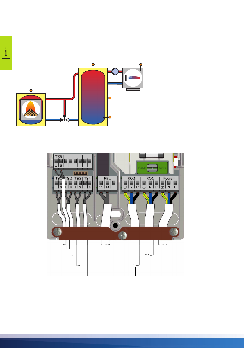
5
Sensor ext. add. heating
Tank sensor, top
Tank sensor, middle
Additional heating pump (230 V AC)
Ext. additional
heating, connection according to
page 47
Tank sensor, bottom
Stove sensor
Power supply (230 V AC)
Request for heat (230 V AC), see
“Connection for request for heat to
RO1” on page 48
Hydraulic system 6: Pellet stove with external additional heating
TS1
RO1
Connection of hydraulic system 6
TS2
RO2
TS3
TS4
REL
TS
TS1: Stove sensor
TS2: Tank sensor, top
TS3: Tank sensor, middle
TS4: Tank sensor, bottom
TS5: Sensor for external
additional heating*
RO1: Request for heat from
pellet
stove
RO2: Additional heating pump*
REL: Ext. additional heating*
* optional
22 smart Stove - 0142 - 42WMSUGAT2-C

HYDRAULIC SYSTEMS
DHW tank sensor
Optional sensor
Tank sensor, middle
Zone valve (230 V AC), see “Connection
of a zone valve to RO1/RO2” on page 46
Space heating
pump, see
“Blocking con-
nection of a
pump to REL” on
page 47
Domestic hot-water pump
Stove sensor
Tank sensor, top
Tank sensor, bottom
Power supply (230 V AC)
Request for heat (230 V AC), see
“Connection for request for heat to
RO1” on page 48
Hydraulic system 7: Pellet stove, tank with charging zones, external domestic hot-water tank
TS1: Stove sensor
TS6
REL
TS6
TS1
RO1
Connection of hydraulic system 7
RO2
TS2
TS8
TS3
TS4
TS2: Tank sensor, top
TS3: Tank sensor, middle
TS5
TS4: Tank sensor, bottom
TS5: Domestic hot-water tank
sensor
TS6: Supply line sensor or outdoor temperature sensor
(optional)
RO1: Request for heat from
pellet
stove
RO2: Zone valve
REL: Space heating pump
TS8: Domestic hot-water pump
smart Stove - 0142 - 42WMSUGAT2-C 23
FUNCTIONS FOR STOVE CONTROL
Functions for stove control
Fire detection
The “fire detection” recognizes, if fire in the wood log or pellet stove is burning.
When fire is detected, a flame symbol will be displayed ( or ).
Fire detection is performed by monitoring the stove temperature (TS1).
Fire detection with pellet stove
If a system with a pellet stove is configured, the option “fire detection with pellets” is available to
allow fire detection in combination with pellets.
• If “fire detection with pellets” is enabled, fire will be detected on and off in the same manner as with
wood log stove.
• If “fire detection with pellets” is disabled, the flame symbol will be highlighted when the request for
heat from the stove (RO1) is active.
Dynamic pump delay (DPD
When the stove is fired, a start condition for the charging pump must be fulfilled.
The dynamic pump delay ›DPD‹ is calculated as the product of temperature and time from the point
when the stove temperature (TS1) passes a set stove temperature ›Charge start‹. When the set
value of ›DPD‹ is reached, the pump starts.
The dynamic pump delay can be set in professional mode, see “Basic functions” on page 55.
Dynamic pump control
The charging pump should be speed-controlled to maintain a fixed stove temperature.
During commissioning, see “Checklist” on page 51, between dynamic pump control, pump speed
control, or combination of both must be selected. Speed control is available only for high efficiency
pumps (PWM or analog 0-10 V).
• In case of using a fixed-speed-pump, the start of the pump is triggered by reaching a fixed stove
temperature ›Charge start‹ and the fulfilled dynamic pump delay ›DPD‹. The dynamic pump con
trol is activated when the stove temperature (TS1) rises above the set stove temperature ›Charge
start‹.
• In case of using a speed-controllable pump, the start of the pump (at minimum speed) is triggered
by reaching a fixed stove temperature ›Charge start‹ and the fulfilled dynamic pump delay ›DPD‹.
The control of the pump is triggered by fulfilling a separate set-point (›Charge start‹ + ›Charge off
set‹) and the product of an increment factor with the minimum pump speed.
The following diagram illustrates the dynamic pump delay and dynamic pump control.
-
-
24 smart Stove - 0142 - 42WMSUGAT2-C
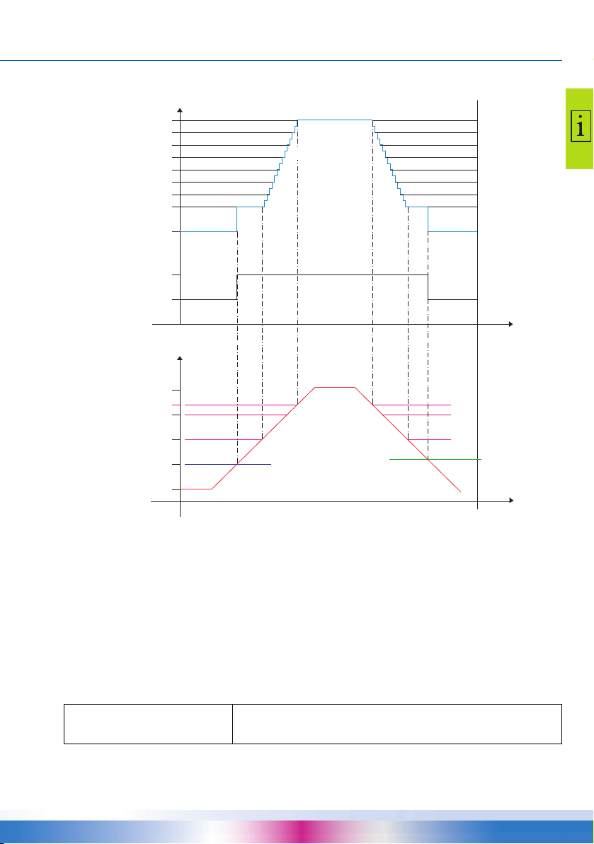
84˚C
50˚C
60˚C
70˚C
30%
(min)
50%
70%
80˚C
90˚C
40%
60%
80%
90%
100%
0
Time
Time
Stove
temperature
Pump control
DPD: Start condition fulfilled
Stop condition
fulfilled
›Charge start‹ +
›Charge offset‹
Increments
ON
OFF
FUNCTIONS FOR STOVE CONTROL
The pump starts when a fixed stove temperature ›Charge start‹ and the dynamic pump delay ›DPD‹
are reached (›Charge start‹
The pump increases its speed above (›Charge start‹ + ›Charge offset‹). With each temperature
increase by 1 K it will speed-up by an adjustable increment (default 5%).
The parameters for dynamic pump control can be set in professional mode, see “Basic functions” on
page 55.
Overtemperature protection
The temperatures of the stove and the tanks are monitored. When overtemperature occurs, at
wood-log stove the charging pump is forced to run. At pellet stove the stove is forced to stop.
The temperature limits can be changed in professional mode, see “Basic functions” on page 55.
* dt).
NOTICE
In order to avoid overheating, the wood log or pellet stove
must be equipped with its own overtemperature protection.
smart Stove - 0142 - 42WMSUGAT2-C 25

FUNCTIONS FOR STOVE CONTROL
Antifreeze protection
If the temperature at any sensor falls below the set value (AF, factory setting: 3°C, range: 2°C 10°C), the pumps will be are activated at 100%. In addition, an alarm message will be generated
(buzzer alarm selectable).
The parameters for antifreeze protection can be set in professional mode, see “Protective functions”
on page 63.
Anti-legionella function
To avoid possible affection of legionella at domestic hot water, a cyclic, thermic treatment shall take
place.
The anti-legionella function is only available, if domestic hot water heating is designated by the
selected hydraulic system.
The anti-legionella functions checks if the minimum temperatures for reduction of legionella has
been achieved in the tank due to heating activity within a set interval.
If no sufficient heating has taken place, the water will be heated up to disinfection temperature, specifically for reduction of legionella.
The installer must set the parameters based on the applicable general directives and local requirements. The time of the disinfection cycle can be determined freely.
The parameters for anti-legionella protection can be set in professional mode, see “Basic functions”
on page 55.
Additional heating
A dynamic recharge delay (DRD) postpones the activation of the additional heating. Before the additional heating is activated, the dynamic recharge delay has to expire.
The dynamic recharge delay is calculated by the minutes*degrees product. The recharging will start
at the calculated temperature point.
The DRD value can be set between 0 and 500 min*K (minutes * degrees Kelvin).
• With DRD = 0, the delay is disabled, additional heating will start immediately.
• Example DRD = 50 min*K: If the tank temperature falls by 10 K (e.g. from 50°C to 40°C), additional heating will start after 5 minutes (5 min * 10 K = 50 min * K). If the tank temperature falls by
5
K, additional heating will start after 10 minutes (10 min * 5 K = 50 min * K).
• Example DRD = 100 min*K: If the tank temperature falls by 10 K, additional heating will start after
10 minutes (10
With a bar graph inside of the heat-generator symbol, you will be informed about the progress of the
dynamic recharge delay.
During the falling of the tank temperature the following will happen:
• When the tank temperature falls below the set-point for additional heating, the calculation will be
started and the bar graph will start with a fully green coloured circle inside of the tank symbol.
• When the tank temperature reaches the calculated temperature of the dynamic recharge delay,
the symbol inside of the tank will switch to fire or electrical flash and the recharging is started.
The parameters for additional heating can be set in professional mode, see “Basic functions” on
page 55.
min * 10 K = 100 min * K), etc.
26 smart Stove - 0142 - 42WMSUGAT2-C
FUNCTIONS FOR STOVE CONTROL
Request for heat
The controller system is designed to control heat for space heating and domestic hot water separately.
For each demand a separate setpoint can be adjusted, one for request heat by stove, one to request
heat by an additional heater.
For example:
• Domestic hot water (DHW) setpoint stove = 65°C
• Domestic hot water (DHW) setpoint additional heater = 55°C
• Space heating (SH) setpoint stove = 50°C
• Space heating (SH) setpoint additional heater = 40°C
An occurring demand by temperature conditions is visualized by little symbol on the information
screen:
Request for heating domestic hot water
Request for space heating
Request for heat with wood log stove
With a wood log stove, a demand will activate an orange blinking background on the stove symbol
as an invitation to make fire. With an little delay, a buzzer will assist the request. The buzzer can be
enabled/disabled optionally.
If fire is made in the stove, it will be detected and the charging pump will be activated and controlled
automatically. With reaching the setpoint (stove), the related demand symbol will vanish.
With undercutting the setpoint for additional heater, what should be set always clear below the setpoint for stove, the additional heater will be activated immediately related to selected mode
(comfort) respectively with dynamic delay (eco).
Request for heat with pellet stove
In combination with an pellet stove, an occurring demand from domestic hot water or space heating
by the stove setpoint will activate the pellet stove. If it is enabled for providing heat, fire will be
detected and displayed, similar to wood log stove.
Request for additional heater is working in the same way as in wood log schemes.
smart Stove - 0142 - 42WMSUGAT2-C 27
THERMOSTAT FUNCTIONS
T OFF
T ON
T ON
T OFF
8:00 9:00
t
ROx
Thermostat functions
The free outputs of the controller can be used as thermostats and/or timers for various applications.
The thermostat functions must be defined in professional mode under ›1.3.1 Thermostat‹, see
“Basic functions” on page 55.
The thermostat functions can also be activated or deactivated in operation mode under ›1.3.1
Thermostat‹, see
Various thermostat and/or timer functions can be defined:
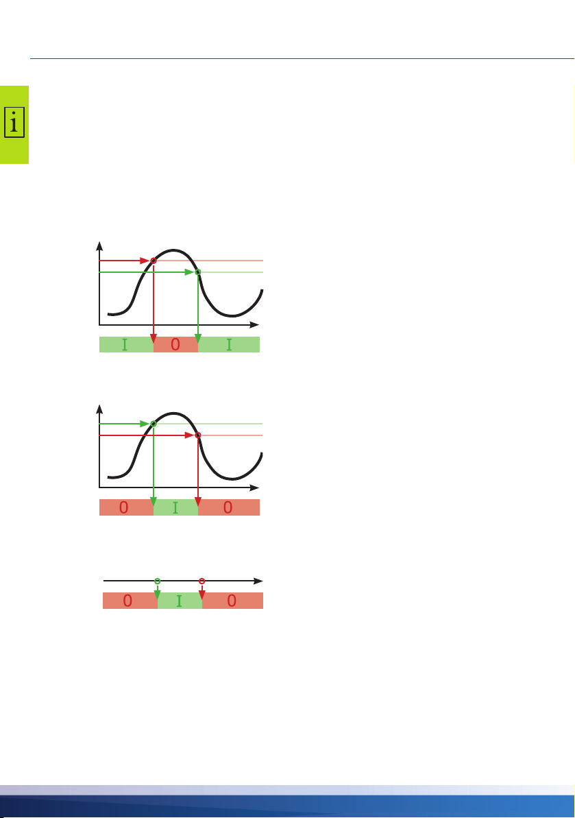
Temperature thermostat “Heating”
“Basic functions” on page 36.
T
ROx
Temperature thermostat “Cooling”
T
ROx
Timer function
T OFF > T ON The output is deactivated once
the ›T OFF‹ temperature is reached, and acti
vated once the ›T ON‹ temperature is reached.
t
T ON > T OFF The output is activated once the
›T ON‹ temperature is reached, and deactivated
once the ›T off‹ temperature is reached.
t
The output is activated within a selected time
frame.
-
28 smart Stove - 0142 - 42WMSUGAT2-C

Timer thermostat
T ON
T OFF
dT ON
Reference sensor
dT OFF
T
t
ROx
±1K
±1K
T ON
T OFF
T
ROx
Temperature comparator
T
TSx
THERMOSTAT FUNCTIONS
Combination of timer and thermostat.
Once at least one of these criteria is met, the
output is activated.
8:00 9:00
t
Any temperature difference to a reference sensor will trigger a control signal:
The output is activated once ›dT ON‹ is
reached, and deactivated once ›dT OFF‹ is
reached.
ROx
t
Temperature thermostat “Window”
The window function is similar to a thermostat function, but with an additional threshold to start and
stop the output. The “window” is defined by two temperature values (lower and upper limits), each
within a defined range. A fixed hysteresis of ±1K for start and stop is added onto the defined limits.
Only a free (unused) output can be used for the window function.
The relay can also be driven inverted.
The output is activated, if the temperature is
between upper and lower limits (± hysteresis).
• The output is switched ON when the lower
limit + hysteresis or the upper limit - hysteresis
is reached.
• The output is switched OFF when the upper
limit - hysteresis or the lower limit + hysteresis
is reached.
smart Stove - 0142 - 42WMSUGAT2-C 29

AUTOMATIC OPERATION
System 1
17.03.2016 09:34
Automatic operation
In automatic mode, the screen displays the date, the time and
the active hydraulic system.
The current temperature is displayed for each temperature
sensor.
Pump operation and valve position are illustrated on the animated display.
There is no need for intervention by the installer or operator.
NOTICE
Check the display screen of the smart Stove on a regular basis
to be able to eliminate any malfunctions promptly!
30 smart Stove - 0142 - 42WMSUGAT2-C

Settings during operation
Anti-blocking *
Antifreeze protect. *
Limits *
Error list
Pump monitoring *
Sensor balancing *
Access code
Manual mode *
Firmwareupdate SD *
Software version
Hardware version
Serial number
Commissioning
Evaluation
Measured values
Service hours
Error list
Main menu
Settings
Date/Time
Language
Display
Buzzer
Rem. SD Card safely
Factory settings
Basic functions
Thermostat
Output parameter *
Commissioning *
Space heating *
Protective functions *
Monitoring
About
Login
Control parameters
Anti-legionellae *
Stop sensor *
Save parameters
Domestic hot water
Menu structure
The following illustration shows the structure of the control menu.
Items marked by an asterisks * are only available in professional mode, see page 54.
NOTICE
SETTINGS DURING OPERATION
The controller does not display any sub menus which are not
required by either the selected hydraulic schema or by the acti
vated options.
smart Stove - 0142 - 42WMSUGAT2-C 31
-

SETTINGS DURING OPERATION
System 1
17.03.2016 10:14
1 Main Menu
17.03.2016 10:14
Evaluation
Settings
Basic functions
Monitoring
Login
1 Main Menu
17.03.2016 10:14
Settings
Basic functions
Monitoring
Login
About SmartStove
1.1 Evaluation
17.03.2016 10:24
Measured values
Service hours
Error list
Main menu
On the controller, you can make various settings and obtain
information about states and processes.
To this effect, press the knob in automatic mode.
›1 Main menu‹ appears.
A list of subitems appears.
By turning the knob ...
...the lower part of the menu is displayed.
Select a subitem by pressing the knob.
Evaluation
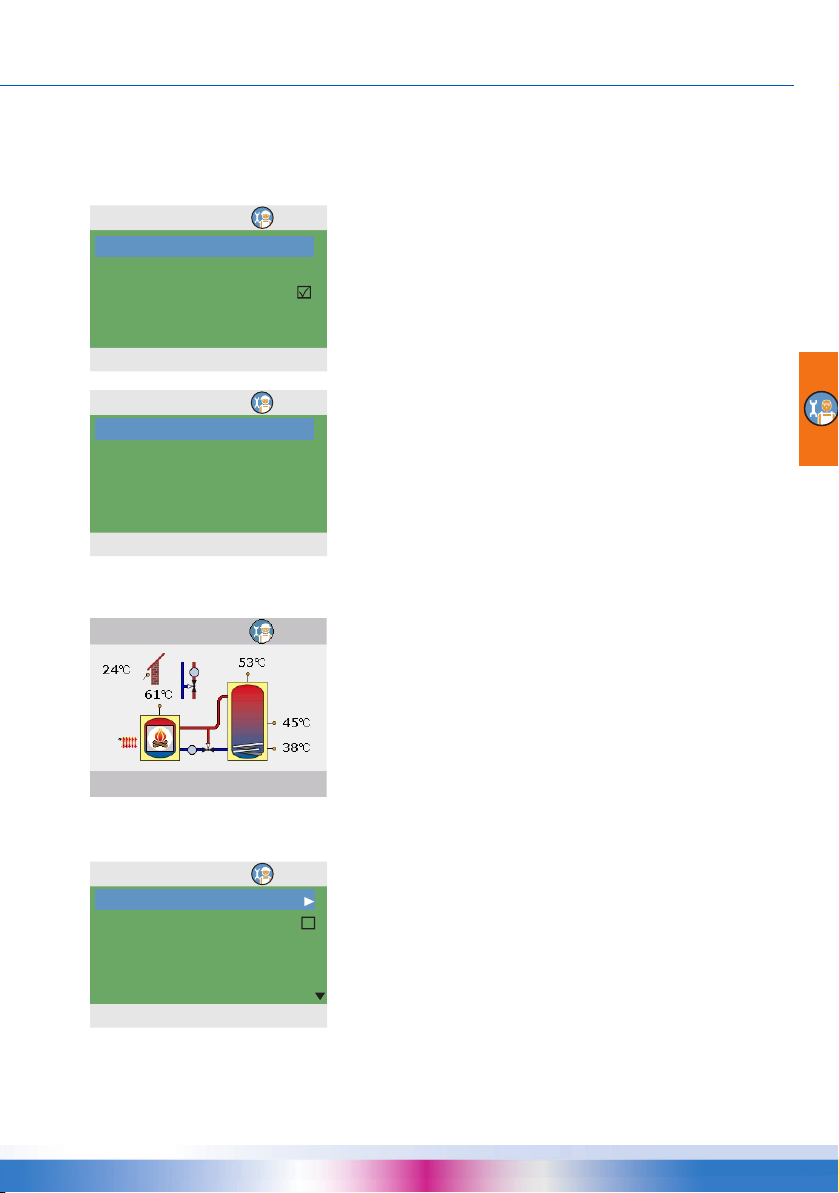
The ›1. Evaluation‹ menu provides information about the differential temperature controller smart Stove and the entire plant.
Select ›Measured values‹.
32 smart Stove - 0142 - 42WMSUGAT2-C

SETTINGS DURING OPERATION
1.1.1 Measured val...
17.03.2016 10:24
Heat source 60.6°C
Tan k t o p. 52.8°C
Tan k m i d . 45.2°C
Tan k b o t . 37.8°C
External DHW 45.2°C
1.1.1 Measured val...
17.03.2016 10:24
Outdoor 13.8°C
Charge pump 100%
Charge zone v Off
DHW pump 100%
SH blocking Off
1.1.2 Service hours
17.03.2016 10:24
Charge pump 4h
Charge zone v 1h
SH blocking 2h
DHW pump 3h
Additional heat 1h
1.1.5 Error list
17.03.2016 10:24
M05: 08:31 03.09
M04: 07:44 03.09
---
---
---
Here, the temperatures and dates concerning the controller
are displayed.
If additional sensors have been defined on commissioning,
these sensors also appear here.
By scrolling ...
...the lower part of the menu is displayed.
Here, the operational status of the pumps and valves is displayed.
›SH blocking‹ indicates the blocking status for space heating.
Return to ›1.1 Evaluation‹.
Select ›Service hours‹.
The operating times of the activated plant components are displayed in hours.
By scrolling down and actuating the menu item ›Reset‹, all
counters will be reset to zero.
Return to ›1.1 Evaluation‹.
Select ›Error list‹.
The ›Error list‹ shows all the error messages of the differential
temperature controller smart Stove in a temporal order.
To view information for an error message, select it.
smart Stove - 0142 - 42WMSUGAT2-C 33
SETTINGS DURING OPERATION
1.1.5 Error list
17.03.2016 10:24
M05:
Sensor short-circuit
on TS3!
Press ESC to return
1.2 Settings
17.03.2016 10:34
Date/Time
Language
Display
Buzzer
Rem.SD card safely
1.2 Settings
17.03.2016 10:34
Buzzer
Rem.SD card safely
Save parameters
---
Factory settings
1.2.1 Time/Date
17.03.2016 10:34
Date 17.03.2016
Time 10:23
Auto. Clock Change
The error message appears in plain text.
If necessary, take the appropriate measures.
Return to ›1 Main menu‹.
Select ›Settings‹.
Settings
In the ›1.2 Settings‹ menu, you can change settings of the differential temperature controller smart Stove.
By scrolling ...
...the lower part of the menu is displayed.
Select ›Date/Time‹.
Here, date and time can be set in case of deviation or an
extended period of de-energizing.
If the differential temperature controller smart Stove is installed
at a location where daylight-saving time exists, the time shift
can be activated by ›Auto Clock Change‹.
Select the subitem ›Date‹ or ›Time‹ by pressing the knob.
34 smart Stove - 0142 - 42WMSUGAT2-C

SETTINGS DURING OPERATION
1.2.1 Time/Date
17.03.2016 10:34
Date 17.03.2016
Time 10:23
Auto. Clock Change
1.2.2 Language
17.03.2016 10:34
Deutsch
English
Français
Italiano
Svenska
1.2.7 Display
17.03.2016 10:34
Brightness 100%
Blanking time 180s
Mirror system
1.2.10 Buzzer
17.03.2016 10:34
Error
Add. heat alert
Stove request
One group of figures each is activated and can be varied via
the knob; whenever the knob is pressed, the activation jumps
to the next group.
Return to ›1.2 Settings‹.
Select ›Language‹.
Here, you can change over to another available language.
Return to ›1.2 Settings‹.
Select ›Display‹.
›Brightness‹ serves to adjust the backlighting of the display in
steps of 10% from 5% to 100%.
›Blanking time‹ is used to determine the time after which, in
case of inactivity, backlighting is reduced from the set value to
10%. Adjustable in the range from 30 to 255 seconds.
Activate ›Mirror system‹ if you want to mirror the hydraulic
scheme display.
Return to ›1.2 Settings‹.
Select ›Buzzer‹.
Here, you can disable or enable for which events the controller
issues acoustic signals.
›Error‹: Acoustic signal for alarms
›Add. heat alert‹: Acoustic signal on request for additional
heat, see page
›Stove request‹: Acoustic signal on request for heat from stove
27
smart Stove - 0142 - 42WMSUGAT2-C 35

SETTINGS DURING OPERATION
1.2 Settings
17.03.2016 10:34
Buzzer
Rem.SD card safely
Save parameter
Successfully saved
Factory settings
1.3 Basic functions
17.03.2016 10:44
Thermostat
Control parameters
Domestic hot water
1.3.1 Thermostat
17.03.2016 10:44
Thermostat HETS7
Thermostat HETS8
1.3.1 Thermostat H...
17.03.2016 10:44
Activation
Return to ›1.2 Settings‹.
Before the SD card can be removed, ›Remove SD card safely‹
must have been selected.
With the ›Save parameter‹ function, the current configuration is
saved on the Micro SD card.
The last menu item is ›Factory settings‹.
By selecting and pressing the knob, followed by ›esc‹, the preset values are deleted and replaced by the factory settings.
Return to ›1 Main menu‹.
Select ›Basic functions‹.
Basic functions
In the ›1.3 Basic functions‹ menu, you can configure thermostat controls, setpoints for domestic hot water and space heating, and enable additional heating (if available).
The menu depends on the selected hydraulic system.
Select ›Thermostat‹.
The controller‘s free outputs can be used as thermostats for
various applications.
In professional mode, presettings must be made to this effect your installer will explain the appropriate function to you, if nec
essary.
By selecting a subitem ...
-
...the appropriate activation screen is displayed.
36 smart Stove - 0142 - 42WMSUGAT2-C

SETTINGS DURING OPERATION
1.3.14 Control para.
17.03.2016 10:44
Add. heat enable
Charge start 58°C
1.3.13 DHW
17.03.2016 10:44
Req. stove 55°C
1.3.13 DHW
17.03.2016 10:44
Req. add. heat 50°C
Req. stove 55°C
DRD DHW Eco
100min*K
1.3.13 DHW
17.03.2016 10:44
DRD DHW Eco
100min*K
DRD DHW Comf
10min*K
Return to ›1.3 Basic functions‹.
Select ›Control parameters‹.
By ›Add. heat enable‹, recharging of the tank by the additional
heating can be disabled or enabled (if available).
By ›Charge start‹, you can set the minimum stove temperature
for starting the loading pump.
Return to ›1.3 Basic functions‹.
Select ›Domestic hot water‹.
By ›Req. stove‹, you can set the minimum stove temperature
for domestic hot water heating.
Only for use with additional heating:
When the buffer tank temperature falls below the ›Req. add.
heat‹, the dynamic recharge delay (DRD) (time x temperature)
is started. When the DRD is reached, additional heating will be
enabeled.
Scroll down.
›DRD DHW Eco‹ is the dynamic recharge delay for domestic
hot water in economy mode.
›DRD DHW Comf‹ is the dynamic recharge delay for domestic
hot water in comfort mode.
Return to ›1 Main menu‹.
Select ›Monitoring‹.
smart Stove - 0142 - 42WMSUGAT2-C 37

SETTINGS DURING OPERATION
1.6 Monitoring
17.03.2016 11:04
Error list
1.1.5 Error list
17.03.2016 11:04
M33: 09:31 03.07
M32: 09:44 03.07
---
---
---
1.1.5 Error list
17.03.2016 11:04
M32:
Check
date and time.
Press ESC to return
1.7 Login
17.03.2016 11:04
Access code 350
Monitoring
In the ›1.6 Monitoring‹ menu, you can view error messages.
The ›Error list‹ shows all the error messages of the differential
temperature controller smart Stove in a temporal order.
To view information for an error message, select it.
The error message appears in plain text.
If necessary, take the appropriate measures.
Return to ›1 Main menu‹.
Select ›Login‹.
Login
In order to enter the professional mode, you must enter the
access code.
See “Settings in the professional mode” on page 54
Return to ›1 Main menu‹.
38 smart Stove - 0142 - 42WMSUGAT2-C
Select ›About‹.

About
1.9 About
17.03.2016 11:04
SmartStove
Software version 3.17
Hardware version 8.01
1.9 About
17.03.2016 11:04
Hardware version 8.01
Serial number
11447
Commissioning
17.03.2016
System 1
17.03.2016 11:04
System
SETTINGS DURING OPERATION
In the ›1.9 About‹ menu, you can find out the software version,
the hardware version, the serial number, and the date of com
missioning of your differential temperature controller smart
Stove.
This information is required for repairs and for version management.
If no entry is made within the preset time (30 - 255 s) on the
smart Stove, the display returns to ›System‹.
Use ›esc‹ to return to the home screen from every menu.
-
smart Stove - 0142 - 42WMSUGAT2-C 39

MOUNTING
Mounting
Dimensions
Opening the terminal cover
DANGER
Electrical hazard
Lethal danger due to electrocution!
Whenever work is performed on the open terminal cover, all
poles of the power supply must be disconnected reliably and
protected against being switched on again!
40 smart Stove - 0142 - 42WMSUGAT2-C
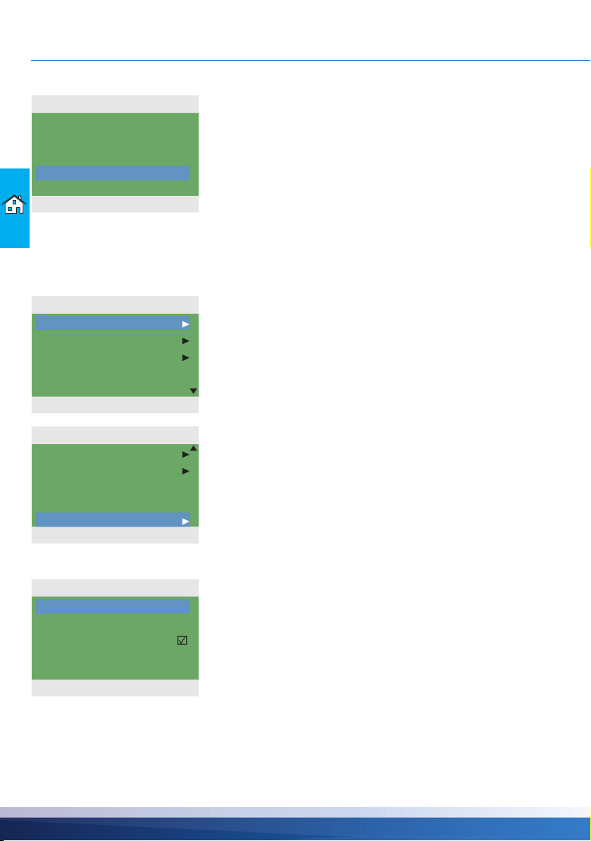
MOUNTING
1 Release the lock screw.
2 Swing terminal cover forward ...
3 ... push it upwards ...
4 ... and remove it.
Store the terminal cover carefully and protect it
against damage!
To close the terminal cover, reverse the opening
procedure.
Wall-mounting
NOTICE
WARNING
The device corresponds to protection type IP 20.
Electrical hazard
Make sure the appropriate prerequisites exist on the place of
installation.
Do not use the housing base as drill template.
A device with damaged housing must not be operated!
smart Stove - 0142 - 42WMSUGAT2-C 41

MOUNTING
1 Fasten the top securing screw so that a
space of 2 to 3 mm is created between the
wall and the screw head.
2 Move the device so that the upper fastening
port is located above the screw head ...
3 ... and push it downwards.
4 Fasten the lower securing screw.
If necessary, use dowels for wall-mounting!
42 smart Stove - 0142 - 42WMSUGAT2-C

Designation of the components
Knob with OK button
Display
esc button
Housing cover
Housing base
Spare fuse
Fuse
Vortex plug connector
Terminals
Break-out segments
Screw connection
strain relief device
Strain relief device
Screw fastening of terminal cover
Terminal cover
Drill hole for securing bolt
MOUNTING
“Opening the terminal cover” on page 40
smart Stove - 0142 - 42WMSUGAT2-C 43

ELECTRICAL CONNECTION
Terminal block
TS1-TS4
Terminal block
TS5-TS8
Terminal block
REL
Terminal block
RO2/RO1/Power
Electrical connection
DANGER
Electrical hazard
Lethal danger due to electrocution!
Whenever work is performed on the open terminal cover, all
poles of the power supply must be disconnected reliably and
protected against being switched on again!
Ter minals
The differential temperature controller smart Stove is connected by four three groups of spring-type
terminals which are visible once the terminal cover is opened.
To introduce the cables, release the three screws on the strain relief device; if necessary, remove
the strain relief device.
In case of flush mounting of the cables, the break-out segments in the housing base can be
removed carefully and the cables routed through these ports.
The central terminal block is the interface to a potential-free change-over contact - here, it may be
necessary to route electrical resistors into the spring-type terminals and to connect part of the
cables via luster terminals.
44 smart Stove - 0142 - 42WMSUGAT2-C
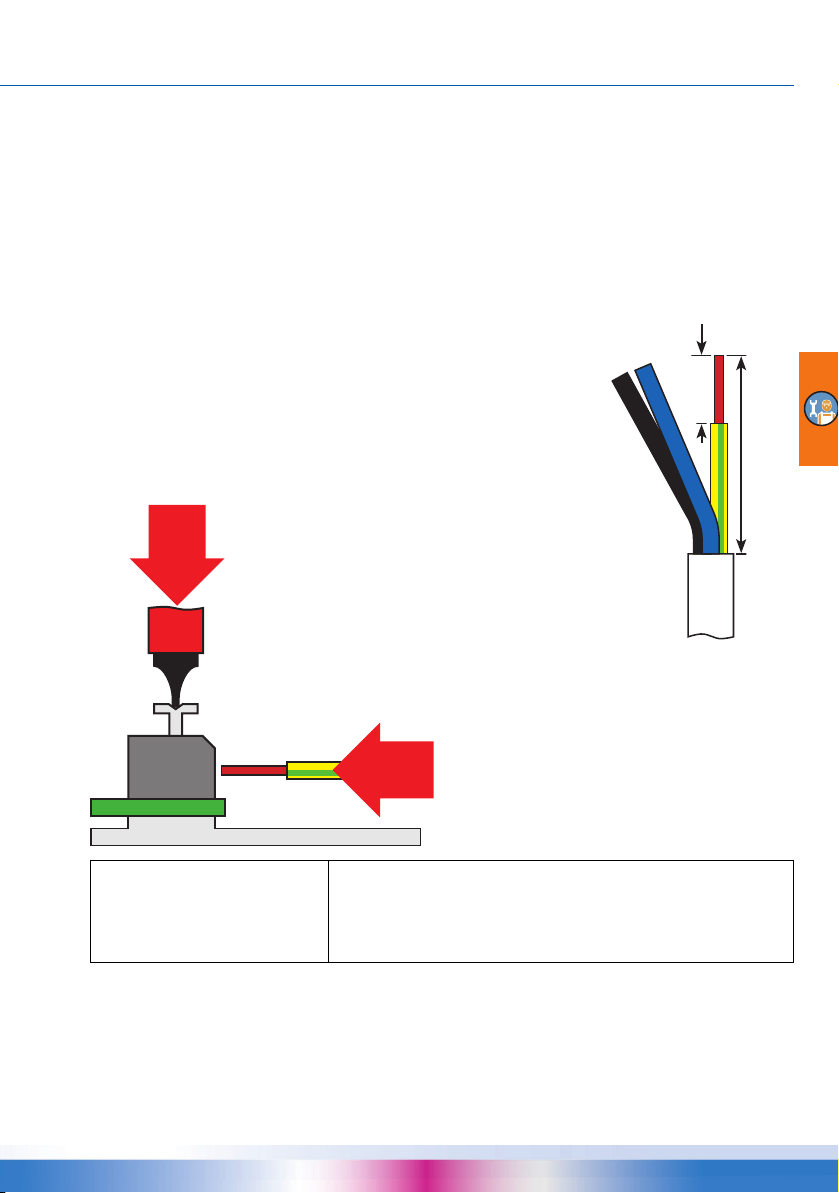
ELECTRICAL CONNECTION
The strain relief device can only ensure solid clamping if the cables are
not stripped to a length of over 35 mm.
Insulation of the individual wires must be removed over a length of 9 10 mm to ensure safe electric contact in the spring-type terminal.
Stranded wires must be provided with cable end sleeves!
For connection, press the actuation push button of the
spring-type terminal using a screwdriver and insert the
wire to its stop in the appropriate port.
Release the actuation push button and pull the
cable slightly to ensure that it is safely clamped.
The spring-type terminals for the power supply, RO1, RO2 and REL, and for TS1 to TS8 can accom-
modate solid wires up to a cross section of 1.5 mm2. Appropriate stranded wires must be preassembled with cable end sleeves.
For the strain relief device function, TS1 to TS7 and REL require cable diameters of at least 5 mm,
for Power, RO1, RO2 at least 7
The strain relief fixture can be slightly reworked to fit larger cable diameters without producing sharp
edges. For a larger number of sensor lines, cable straps can be used to support the strain relief.
Cable preparing
mm.
9-10 mm
max.
35 mm
NOTICE
Before closing the terminal cover, make sure the strain relief
device is tightened safely.
Check once more that all cables are in good condition and
connected correctly.
smart Stove - 0142 - 42WMSUGAT2-C 45
ELECTRICAL CONNECTION
Val ve
Val ve
Val ve
Val ve
Relay: n.o.
Attention! Maximum switching capacity 230VA
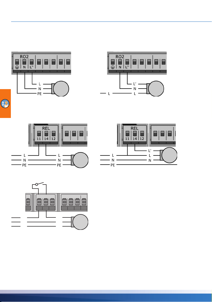
Connection of a zone valve to RO1/RO2
Connection diagram for a zone valve without
power supply to RO2:
Connection of a zone valve to REL
Connection diagram for a zone valve with power
supply to RO2:
Connection diagram for a zone valve without
power supply to REL:
Connection of a pump to REL
REL
11 14 12
L
N
PE
L
N
PE
Connection diagram for a zone valve with power
supply to REL:
46 smart Stove - 0142 - 42WMSUGAT2-C
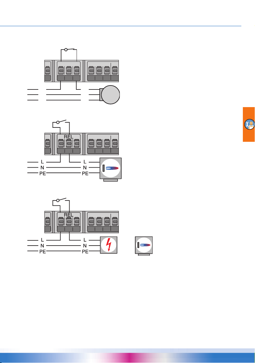
Blocking connection of a pump to REL
Relay: n.c.
Attention! Maximum switching capacity 230VA
Relay: n.o.
Attention! Maximum switching capacity 230VA
Relay: n.o.
Attention! Maximum switching capacity 230VA
or
REL
11 14 12
ELECTRICAL CONNECTION
L
N
PE
Connection of a boiler to REL
11 14 12
Connection of an external heat source to REL
11 14 12
L
N
PE
smart Stove - 0142 - 42WMSUGAT2-C 47

ELECTRICAL CONNECTION
11 14 12
Relay: n.c.
Attention! Maximum switching capacity 230VA
or
External relay n.c.
230 V AC
External relay n.o.
230 V AC
Blocking connection of an external heat source to REL
Blocking connection of a pump to RO2
L
N
PE
Connection for request for heat to RO1
RO1
High-efficiency pump
A high-efficiency pump can be connected via RO1 or RO2.
The appropriate control signal is issued at TS7/TS8.
The control signal may be an analog voltage 0 - 10V or a PWM signal.
48 smart Stove - 0142 - 42WMSUGAT2-C
L
N
PE
L‘
N

ELECTRICAL CONNECTION
RO1 or RO2: 230V supply
of the high-efficiency pump
TS7/TS8: PWM-control signal for the highefficiency pump
Left-hand terminal: GND
Right-hand terminal: Signal
For further details, please refer to the pump specification.
For definition and settings, the professional mode under ›1.3.7 Output parameter‹ has been provided.
NOTICE
smart Stove - 0142 - 42WMSUGAT2-C 49
High-efficiency pumps are supplied with proportional or
inverted control signals. (Only inverted for PWM control.)
Inverted
100%
Proportional
0
The pump type is selected during commissioning, see
page
51.
10V analog/
100% PWM

COMMISSIONING
0.1 Language
17.03.2016 09:14
Deutsch
English
Français
Italiano
Español
Date 17.03.2016
Time 09:14
Auto. Summer time
Load from SD card
Next
17.03.2016 09:14
0.2 Time/Date
Commissioning
NOTICE
This is an explanation in terms of an example of commissioning of the differential temperature controller smart Stove; details vary along with the hydraulic configuration and the software version.
The differential temperature controller smart Stove accompanies you during the entire configuration
and interrogates everything it must know for optimum operation.
The power supply of the controller must be switched on - the display screen appears.
Basic settings
For commissioning, the controller must be assembled correctly, all inputs and outputs must be connected and ready for
operation, the strain relief device must be screw-fastened and
the terminal cover closed!
›0.1 Language‹ appears after a short booting sequence.
Various languages are available in this version of the smart
Stove.
Activate the required language by turning the knob and
acknowledge it by pressing the knob.
Scroll down and select ›Next‹.
›0.2 Time/Date‹ appears.
Press the knob, the first value will be highlighted.
Turn the knob until the correct value is displayed and acknowledge by pressing the knob.
Enter all values in this way.
At any place of installation where European daylight saving
time is applicable, the automatic time difference can be acti
vated here.
To change the setting, select ›Auto Summer time‹ and press
the knob.
There are the following possibilities to continue:
• “Choose system” on page 51
• “Load an existing configuration” on page 51
-
50 smart Stove - 0142 - 42WMSUGAT2-C
COMMISSIONING
0.2 Time/Date
Date 17.03.2016
Time 09:14
Auto. Summer time
Load from SD card
Next
17.03.2016 09:14
0.5 File list
17.03.2016 09:14
04271230.STV
06041715.STV
System 1
17.03.2016 09:14
0.7 Checklist
17.03.2016 09:14
Tes t out p ut s
Mirror system
Supply Sensor --Outdoor Sensor --HE signal TS7 ---
Load an existing configuration
If there is a Micro SD card with an already saved configuration, insert it in the device before starting
commissioning.
Select ›Load from SD card‹ and acknowledge.
A list of pre-configured plant settings is displayed.
Select the desired file and acknowledge.
The configuration is loaded and the settings are applied in the
following commissioning.
The files are on the SD card in the ›PARAMS‹ folder. It is possible to change the file names on the PC: Max. 8 characters,
only letters and figures. Do not change the file extension!
Choose system
After selecting ›Next‹, the graphic illustration of a hydraulic
system is shown.
Scroll through all available hydraulic sc hem as by turning the
knob, select the illustrated hydraulic schema by pressing the
knob.
Then, any parameters relevant for the selected hydraulic
schema are queried.
Checklist
›0.7 Checklist‹ appears.
The menu depends on the selected hydraulic system.
Check the function of the connected pumps and valves by
selecting ›Test outputs‹.
smart Stove - 0142 - 42WMSUGAT2-C 51
COMMISSIONING
0.7.1 Test outputs
17.03.2016 09:14
RO1 Off
RO2 Off
REL Off
TS8 Off
Next
0.7 Checklist
17.03.2016 09:14
Tes t out p ut s
Mirror system
Supply Sensor --Outdoor Sensor --HE signal TS7 ---
0.7 Checklist
17.03.2016 09:14
Tes t out p ut s
Mirror system
Supply Sensor
TS5
Outdoor Sensor TS6
HE signal TS7 ---
›0.7.1 Test outputs‹ appears.
The menu depends on the selected hydraulic system.
Select an output, acknowledge, select ›On‹ on the knob and
activate it. The connected pump and/or the connected valve
must now be activated.
Complete the test operation by pressing ›Next‹.
NOTICE
If the hydraulic installation does not comply with the standard,
or if special products were used which cause incorrect valve
positions during test operation, the ›Inverted‹ option must be
activated by accessing the corresponding output menu 1.3.7 in
professional mode after commissioning.
The controller will then exchange energized and de-energized
conditions.
You can mirror the hydraulic scheme display, i.e. the buffer
tank will be displayed on the other side of the boiler.
Activate ›Mirror system‹ if your plant is that way.
Note: ›Mirror system‹ does not influence the functions of the
controller.
The further menu items depend on the selected hydraulic system.
If a temperature sensor for space heating is installed, select it
by the ›Supply Sensor‹ item.
If an outdoor temperature sensor is installed, select it by the
›Outdoor Sensor‹ item.
Note: The availability of temperature sensors depends on the
selected system. By selecting a temperature sensor, the
regarding functions are enabled simultaneously.
52 smart Stove - 0142 - 42WMSUGAT2-C

COMMISSIONING
0.7 Checklist
17.03.2016 09:14
Tes t out p ut s
Mirror system
Supply Sensor
TS5
Outdoor Sensor TS6
HE signal TS7PWM 0-100
0.7 Checklist
17.03.2016 09:14
Tes t out p ut s
Mirror system
Ext. heat
Gas
Pump, ext. heater
HE signal TS8 0-10V
0.7 Checklist
17.03.2016 09:14
HE signal TS7PWM 0-100
Common Eco/Comf
Fire Detection
Tank bottom sensor
Next
0.9 End
17.03.2016 09:14
You have comp leted
commissioning!
Next
In ›HE signal TS7‹/›HE signal TS8‹, you select the type of high
efficiency pump which is connected to TS7/TS8:
›PWM 0-100‹, ›PWM 100-0‹ (i.e. inverted), ›0-10V‹, or none
Or
If the hydraulic system 6 with an additional boiler is selected,
choose the heat source in the ›Ext. heat‹ item:
›Electric‹, ›Gas‹, ›Heat pump‹, ›Oil‹, ›Pellet‹, or ›None‹
If the pump for the additional boiler is controlled by smart
Stove, activate ›Pump, ext. heater‹.
In ›HE signal TS8‹, you select the type of high efficiency pump
which is connected to TS8:
›PWM 0-100‹, ›PWM 100-0‹ (i.e. inverted), ›0-10V‹, or none
Scroll down.
By ›Common Eco/Comf‹, the ›Operation mode‹, see page 13,
will be activated for space heating and domestic hot water
simultaneously.
By ›Fire Detection‹, you can disable or enable fire detection for
the stove, see page
By ›Tank bottom sensor‹, you can disable or enable the bottom
tank temperature sensor (TS4).
Acknowledge by selecting ›Next‹.
24.
›0.9 End‹ appears.
By selecting ›Next‹, the controller changes over to automatic
mode.
Commissioning is complete.
From now on, the wood log or pellet stove plant is controlled
automatically.
smart Stove - 0142 - 42WMSUGAT2-C 53

SETTINGS IN THE PROFESSIONAL MODE
1.7 Login
17.03.2016 13:14
Access code 350
Edit
17.03.2016 13:14
Access code
365
Restore last value
Fact ory settings
1 Main Menu
17.03.2016 13:14
Evaluation
Settings
Basic functions
Protective functions
Monitoring
Settings in the professional mode
Login
NOTICE
In professional mode, settings are made which require detailed
knowledge of the heating as well as wood log or pellet stove
plants.
Moreover, solid specialist knowledge regarding control engineering, hydraulics and wood heating is required!
If a single parameter is changed, this may affect the safety,
function, and efficiency of the entire plant!
Leave the settings in professional mode to a specialist workshop, the installer!
Modifications by non-experts tend to result in damage to the
plant, rather than to an improvement of its efficiency!
To enter the professional mode, select ›1.7 Login‹ from the
main menu, activate it and ...
... enter the access code.
The access code to professional mode is ›365‹.
The fact that the installer must be available for his/her customers on 365 days per year may serve as a mnemonic trick.
If the professional mode is not exited actively, the controller
automatically displays the plant layout after the preset display
shut-off time and the access code is reset to 350.
Main menu
After having returned to ›1 Main menu‹, the screen shows a
similar list of subitems as in operation mode.
›Protective functions‹ is additionally available.
54 smart Stove - 0142 - 42WMSUGAT2-C

Evaluation
1.1 Evaluation
17.03.2016 13:14
Measured values
Service hours
Error list
1.2 Settings
17.03.2016 13:24
Date/Time
Language
Display
Buzzer
Rem.SD card safely
1.3 Basic functions
17.03.2016 13:34
Thermostat
Output parameter
Commissioning
Control parameters
Domestic hot water
1.3 Basic functions
17.03.2016 13:34
Control parameters
Domestic hot water
Anti-legionellae
Space heating
Stop sensor
Settings
Basic functions
SETTINGS IN THE PROFESSIONAL MODE
The menu ›1.1 Evaluation‹ is identical to that in the operating
mode.
“Evaluation” on page 32
The menu ›1.2 Settings‹ is also identical to that in the operating mode.
“Settings” on page 34
Under ›1.3 Basic functions‹, the following items are additionally available next to the operation mode menus:
- ›Output parameter‹
- ›Commissioning‹
- ›Anti-legionellae‹
- ›Space heating‹
- ›Stop sensor‹
The ›Thermostat‹, ›Control parameters‹, and ›Domestic hot
water‹ menus contain additional parameters.
Call up the menu item ›Thermostat‹.
smart Stove - 0142 - 42WMSUGAT2-C 55

SETTINGS IN THE PROFESSIONAL MODE
1.3.1 Thermostat
17.03.2016 13:34
Thermostat HETS7
Thermostat HETS8
1.3.1 HE TS8
17.03.2016 13:34
Activation
Start
Timer,thermostat
Output TS8
HE sig. TS8 PWM 0-100
1.3.1 HE TS8
17.03.2016 13:34
Output TS7
HE sig. TS8 PWM 0-100
T ON 40.0°C
T OFF 55.0°C
f PWM 1000Hz
1.3.1 HE TS8
17.03.2016 13:34
t OFF 2 00:00
t ON 3 00:00
t OFF 3 00:00
t ON 4 00:00
t OFF 4 00:00
Any controller outputs which are not assigned can be configured as a thermostat.
Select the appropriate thermostat/output.
Perform activation.
Define in ›Start‹ the thermostat or timer function, see page 28.
Depending on the selection of ›Start‹, the following parameters
are shown.
The output has already been defined by the selection - the
related sensor remains to be defined.
In ›HE sig. TS8‹, you select the type of high efficiency pump
which is connected to TS8:
›PWM 0-100‹ or ›PWM 100-0‹ (i.e. inverted)
Scroll down.
Define switch-ON/OFF temperatures:
For the heating function, T ON must be < T OFF.
For the cooling function, T ON must be > T OFF.
In ›f PWM‹, you define the PWM frequency.
In case a timer function has been selected, up to four time
slots can be assigned to each thermostat function.
Scroll down.
First define the times for activation ›t ON‹ and then for deactivation ›t OFF.
Return to ›1.3 Basic functions‹.
Select ›Output parameter‹.
56 smart Stove - 0142 - 42WMSUGAT2-C

SETTINGS IN THE PROFESSIONAL MODE
1.3.7 Outputs
17.03.2016 13:34
Charge zone v
1.3.7 Outputs
17.03.2016 13:34
Inverted
0 Welcome
17.03.2016 13:34
You really want to
start commission.?
No Yes
1.3.14 Control para.
17.03.2016 10:44
Add. heat enabled
Charge start 58°C
Charge offset 5K
DPD
0min*K
The menu is only available for systems with charge zone valve
(systems 2, 3, 7).
Select ›Charge zone v‹.
The ›Inverted‹ function inverts the switching function of the
valve, e.g. if valve installation does not comply with the
standard.
The controller will then exchange energized and de-energized
conditions.
Return to ›1.3 Basic functions‹.
Select ›Commissioning‹.
Here, new commissioning can be started - e. g. if the hydraulic
system has been changed.
Select ›Yes‹ to start commissioning.
“Commissioning” on page 50
System 1:
Return to ›1.3 Basic functions‹.
Select ›Control parameters‹.
The menu depends on the selected hydraulic system.
›Add. heat enabled‹: Recharging of the tank by the additional
heating can be disabled or enabled (if available)
›Charge start‹: Minimum stove temperature for starting the
loading pump
›Charge offset‹: Temperature offset for starting the
speed
control of the loading pump
›DPD‹: Dynamic pump delay, see page 24
smart Stove - 0142 - 42WMSUGAT2-C 57

SETTINGS IN THE PROFESSIONAL MODE
1.3.14 Control para.
17.03.2016 10:44
High. imm. heater
Min control PWM 30%
Step PWM 5%
1.3.14 Control para.
17.03.2016 10:44
Add. heat enabled
Charge start 58°C
Charge offset 5K
Act. ZV below 43°C
Offset ZV act. 2K
1.3.14 Control para.
17.03.2016 10:44
DPD
0min*K
High. imm. heater
fix PWM 100%
Min control PWM 30%
1.3.14 Control para.
17.03.2016 10:44
High. imm. heater
fix PWM 100%
Min control PWM 30%
Step PWM 5%
›High. imm. heater‹: Force start and stop sensor to TS2 for
additional heating. This option shall be activated if the immer
sion heater is positioned high in the buffer tank.
›Min control PWM‹: Lower PWM speed level for controlling the
stove charging pump
›Step PWM‹: PWM pump speed increment
Systems 2, 3:
›Add. heat enabled‹: Recharging of the tank by the additional
heating can be disabled or enabled (if available)
›Charge start‹: Minimum stove temperature for starting the
loading pump
›Charge offset‹: Temperature offset for starting the
speed
control of the loading pump
›Act. ZV below‹: Lower temperature threshold for activation of
zone valve
›Offset ZV act.‹: Temperature offset (hysteresis) for zone valve
activation
›DPD‹: Dynamic pump delay, see page 24
-
›High. imm. heater‹: Force start and stop sensor to TS2 for
additional heating. This option shall be activated if the immer
sion heater is positioned high in the buffer tank.
›fix PWM‹: Fixed PWM speed of high efficiency pump for loading domestic hot water
›Min control PWM‹: Lower PWM speed level for controlling the
stove charging pump
›Step PWM‹: PWM pump speed increment
58 smart Stove - 0142 - 42WMSUGAT2-C
-

Systems 4, 5:
1.3.14 Control para.
17.03.2016 10:44
Add. heat enabled
Charge start
58°C
High. imm. heater
1.3.14 Control para.
17.03.2016 10:44
Add. heat enabled
Charge start
58°C
Ext. AH pump On 5K
Ext. AH pump Off 2K
fix PWM 100%
1.3.14 Control para.
17.03.2016 10:44
Charge start 58°C
Act. ZV below 43°C
Offset ZV act. 2K
fix PWM 100%
System 6:
System 7:
SETTINGS IN THE PROFESSIONAL MODE
›Add. heat enabled‹: Recharging of the tank by the additional
heating can be disabled or enabled (if available)
›Charge start‹: Minimum stove temperature for starting the
loading pump
›High. imm. heater‹: Force start and stop sensor to TS2 for
additional heating. This option shall be activated if the immer
sion heater is positioned high in the buffer tank.
›Add. heat enabled‹: Recharging of the tank by the additional
heating can be disabled or enabled (if available)
›Charge start‹: Minimum stove temperature for starting the
loading pump
›Ext. AH pump On‹: Switch-on temperature offset (hysteresis)
for additional heating pump
›Ext. AH pump Off‹: Switch-off temperature offset (hysteresis)
for additional heating pump
›fix PWM‹: Fixed PWM speed of high efficiency pump for external heat source
›Charge start‹: Minimum stove temperature for starting the
loading pump
›Act. ZV below‹: Lower temperature threshold for activation of
zone valve
›Offset ZV below‹: Temperature offset (hysteresis) for zone
valve activation
›fix PWM‹: Fixed PWM speed of high efficiency pump for loading domestic hot water
-
Return to ›1.3 Basic functions‹.
Select ›Domestic hot water‹.
smart Stove - 0142 - 42WMSUGAT2-C 59
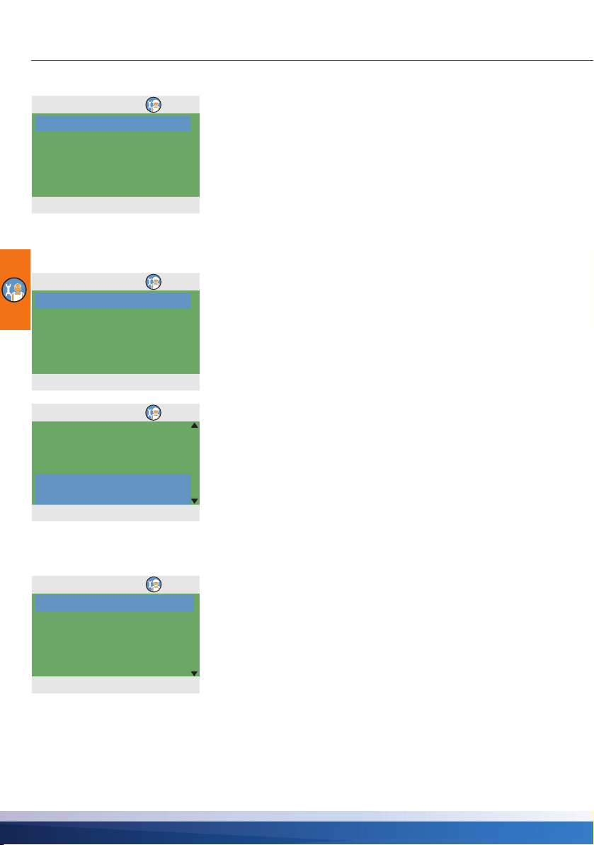
SETTINGS IN THE PROFESSIONAL MODE
1.3.13 DHW
17.03.2016 10:44
Req. stove 55°C
Offset stove 10K
Max. temp DHW 60°C
Charge diff DHW 3K
Charge hys DHW 6K
1.3.13 DHW
17.03.2016 10:44
Req. add. heat 50°C
Offset add. heat 5K
Reg. stove 55°C
Offset stove 10K
Max. temp DHW 60°C
17.03.2016 13:34
Offset stove 10K
DRD DHW Eco
100min*K
DRD DHW Comf
20min*K
1.3.13 DHW
1.5.4 Anti-legionellae
17.03.2016 13:54
Tar ge t t e mp 60.0°C
Hysteresis 3.0°C
Start time 3h
Duration 10min
Max. time 48h
›Req. stove‹: Setpoint for request for heat from stove. If the
tank temperature falls below this temperature the request will
be activated, see page
›Offset. stove‹: Offset for deactivating request for heat from
stove
›Max. temp DHW‹: Maximum temperature for external domestic hot water tank
›Charge diff DHW‹ and ›Charge hys DHW‹ control the pump
for domestic hot water with the following conditions:
TS2 > TS5 + Charge diff DHW and
TS5 < Max. temp DHW – Charge hys DHW
With additional heating:
›Req. add. heat‹: Setpoint for request for heat from additional
heating. If the tank temperature falls below this temperature
the request will be activated, see page
›Offset. add. heat‹: Offset for deactivating request for heat
from additional heating
Scroll down.
›DRD DHW Eco‹: Dynamic recharge delay for domestic hot
water heating - economy mode
›DRD DHW Comf‹: Dynamic recharge delay for domestic hot
water heating heating - comfort mode
27.
27.
Return to ›1.3 Basic functions‹.
Select ›Anti-legionellae‹.
The anti-legionella parameters must be set based on the applicable national regulations.
›Target temp‹: Target temperature for disinfection
›Hysteresis‹: Temperature hysteresis for switch-on
›Start time‹: Starting time for heating
›Duration‹: Duration of the required heating cycle
›Max. time‹: Maximum heating period (timeout)
60 smart Stove - 0142 - 42WMSUGAT2-C
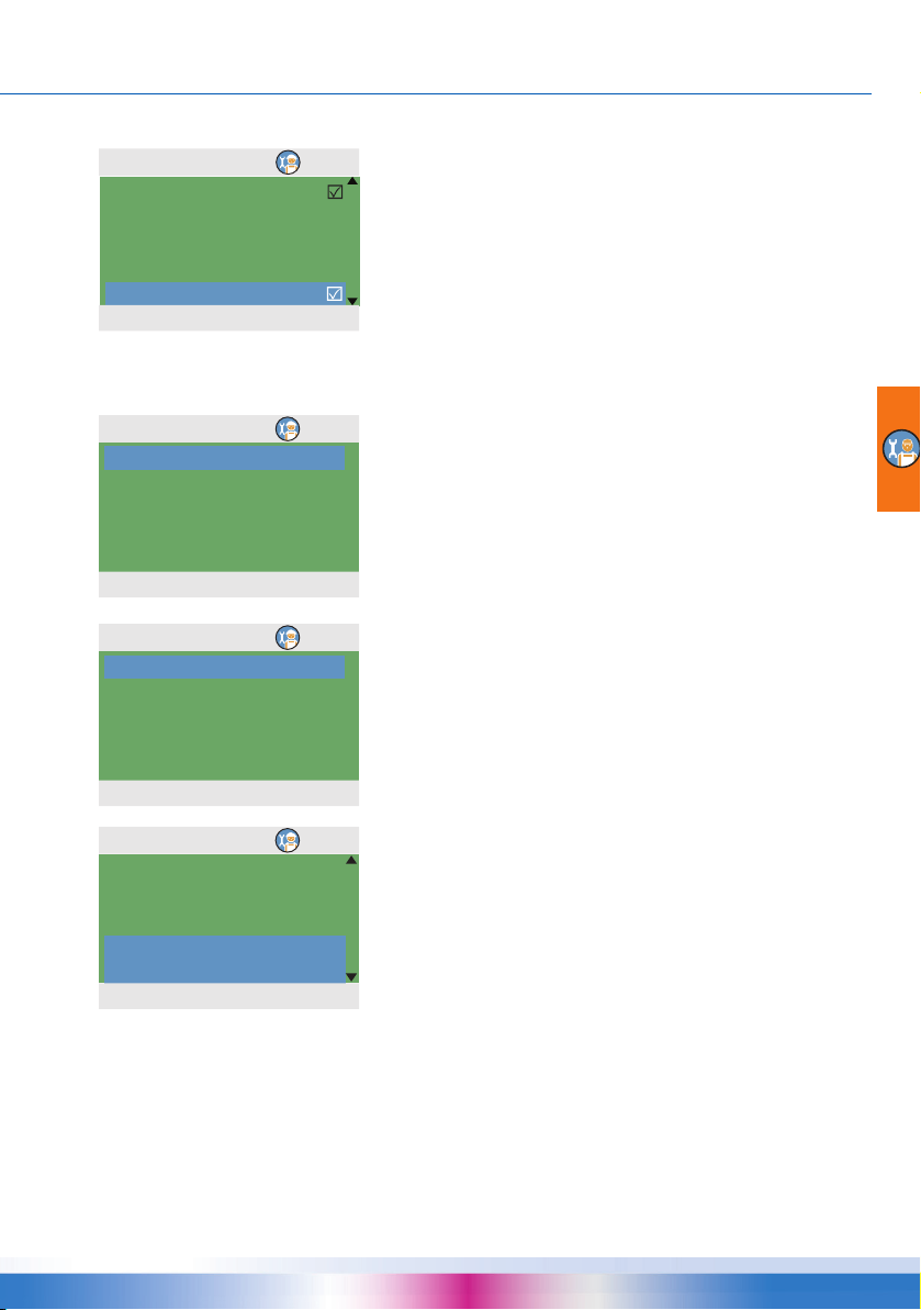
SETTINGS IN THE PROFESSIONAL MODE
1.5.4 Anti-legionellae
17.03.2016 13:54
Use add. heat
Delay add. heat 72h
Day Monday
Interval 7 days
Allow any heat
17.03.2016 13:34
Block SH below 43°C
Offset SH block. 2K
Req. stove 55°C
Offset stove 10K
1.3.9 Space heating
17.03.2016 13:34
Block SH below 43°C
Offset SH block. 2K
Req. add. heat 50°C
Offset add. heat 5K
Req. stove 55°C
1.3.9 Space heating
17.03.2016 13:34
Offset stove 10K
DRD SH Eco
100min*K
DRD SH Comf
20min*K
1.3.9 Space heating
Scroll down.
›Use add. heat‹: Use additional heating for disinfection
›Delay add. heat‹: Time delay for heating cycle with additional
heating
›Day‹: Day of week for disinfection
›Interval‹: Repetition interval for disinfection
›Allow any heat‹: Use any heat source for disinfection
Return to ›1.3 Basic functions‹.
Select ›Space heating‹.
›Block SH below‹: Tank temperature for blocking space heating
›Offset SH block‹: Temperature offset (hysteresis) for blocking
space heating
›Req. stove‹: Required tank temperature for space heating
with stove
›Offset. stove‹: Tank temperature offset (hysteresis) for space
heating with stove
With additional heating:
›Req. add. heat‹: Setpoint for request for heat from additional
heating. If the tank temperature falls below this temperature
the request will be activated, see page
›Offset. add. heat‹: Offset for deactivating request for heat
from additional heating
27.
›DRD SH Eco‹: Dynamic recharge delay for space heating economy mode
›DRD SH Comf‹: Dynamic recharge delay for space heating comfort mode
smart Stove - 0142 - 42WMSUGAT2-C 61

SETTINGS IN THE PROFESSIONAL MODE
17.03.2016 13:34
Stove DHW Eco TS3
Stove DHW Comf TS3
Stove SH Eco TS3
Stove SH Comf TS3
1.3.16 Stop sensor
17.03.2016 13:34
AH DHW Eco TS2
AH DHW Comf TS3
Stove DHW Eco TS3
Stove DHW Comf TS3
AH SH Eco TS2
1.3.16 Stop sensor
17.03.2016 13:34
Stove DHW Comf TS3
AH SH Eco TS2
AH SH Comf TS3
Stove SH Eco TS3
Stove SH Comf TS3
1.3.16 Stop sensor
Return to ›1.3 Basic functions‹.
Select ›Stop sensor‹.
Here, you can define the temperature sensors which are used
for stopping the demands. In general, two sensors are used for
controlling the functions: The switch-on sensor (positioned on
top) and the switch-off sensor, which can be selected here
depending on the ›Operating mode‹.
The menu items with additional heating ›... AH ...‹ are hidden
when >High imm. heater< is enabled.
The menu depends on the selected hydraulic system.
›Stove DHW Eco‹: Temperature sensor for domestic hot water
with stove in economy mode
›Stove DHW Comf‹: Temperature sensor for domestic hot
water with stove in comfort mode
›Stove SH Eco‹: Temperature sensor for space heating with
stove in economy mode
›Stove SH Eco Comf‹: Temperature sensor for space with
stove heating in comfort mode
Or
›AH DHW Eco‹: Temperature sensor for domestic hot water
with additional heating in economy mode
›AH DHW Comf‹: Temperature sensor for domestic hot water
with additional heating in comfort mode
›Stove DHW Eco‹: Temperature sensor for domestic hot water
with stove in economy mode
›Stove DHW Comf‹: Temperature sensor for domestic hot
water with stove in comfort mode
›AH SH Eco‹: Temperature sensor for space heating with additional heating in economy mode
›AH SH Comf‹: Temperature sensor for space heating with
additional heating in comfort mode
›Stove SH Eco‹: Temperature sensor for space heating with
stove in comfort mode
›Stove SH Comf‹: Temperature sensor for space heating with
stove in comfort mode
Return to ›Main menu‹.
62 smart Stove - 0142 - 42WMSUGAT2-C
Select ›Protective functions‹.

Protective functions
1.5 Protective funct...
17.03.2016 13:54
Anti-blocking
Antifreeze protect.
Limits
1.5.1 Anti-block pr...
17.03.2016 13:54
Start 11:00
Duration 5s
Charge pump
SH blocking
DHW pump
1.5.3 Antifreeze pr...
17.03.2016 13:54
Activation
Min.temperature 3.0°C
Hysteresis 2K
SETTINGS IN THE PROFESSIONAL MODE
In professional mode, the ›1.5 Protective functions‹ menu is
additionally available. It has the following items:
- ›Anti-Blocking‹
- ›Antifreeze protection‹
- ›Limits‹
Select ›Anti-Blocking‹.
The pumps and valves can be moved daily to prevent them
from getting blocked.
This function is not activated as long as the pumps are activated in normal operation.
Determine the time of the day and the operating period.
Activate the required pumps and valves.
Return to ›1.5 Protective functions‹.
Select ›Antifreeze protect.‹
NOTICE
The antifreeze protection function may prevent the heating
system from damage which could be caused by freezing
medium.
Enter the lowest temperature ›Min.temperature‹ at which a
system filled with pure water without antifreeze could operate
without suffering damage.
Activation and setting of the anti-freeze protective function.
Change the anti-freeze protection temperature and activation
interval via ›Min.temperature‹ and ›Hysteresis‹.
Return to ›1.5 Protective functions‹.
Select ›Limits‹.
smart Stove - 0142 - 42WMSUGAT2-C 63

SETTINGS IN THE PROFESSIONAL MODE
17.03.2016 13:34
TS1 Limit 85°C
TS2 Limit 85°C
TS3 Limit 85°C
TS4 Limit 75°C
TS5 Limit 75°C
1.3.12 Limits
1.6 Monitoring
17.03.2016 14:04
Error list
Pump monitoring
Sensor balancing
1.6.6 Pump monito...
17.03.2016 14:04
Activation
Tem p . ch a nge 1 0.5K
Tem p . ch a nge 2 0.5K
Monitoring time 15min
1.6.5 Sensor balan...
17.03.2016 14:04
TS1 Offset 0.0°C
TS2 Offset 0.0°C
TS3 Offset 0.0°C
TS4 Offset 0.0°C
TS5 Offset 0.0°C
Here, the limits for overtemperature protection can be
changed.
›TS1 Limit‹: Limit for overload of fuel in stove
›TS2 Limit‹ to ›TS4 Limit‹: Limits for tank temperature too high
›TS5 Limit‹: Limits for hot-water tank temperature too high
(hydraulic systems 3 and 7 only)
Return to ›Main menu‹.
Select ›Monitoring‹.
Monitoring
Under ›1.6 Monitoring‹, the following items are additionally
available next to the operation mode menus:
- ›Pump monitoring‹
- ›Sensor balancing‹
Select ›Pump monitoring‹.
When activated, ›Pump monitoring‹ observes the temperature
change during the ›Monitoring time‹.
If the temperature does not change during this time, the controller releases an alarm.
Continue with ›Sensor balancing‹.
Long piping and other factors may distort measured variables.
Here, an offset value can be entered for each sensor.
Return to ›Main menu‹.
64 smart Stove - 0142 - 42WMSUGAT2-C
Select ›Login‹.

SETTINGS IN THE PROFESSIONAL MODE
1.7 Login
17.03.2016 14:14
Access code 365
Manual mode
Firmwareupdate SD
1.7.1 Manual mode
17.03.2016 14:14
Charge pump Auto
Speed 100%
Status
---
SpaceHeating Auto
1.7 Login
17.03.2016 14:14
Access code 365
Manual mode
Firmwareupdate SD
Login
Continue with ›Manual mode‹.
Manual mode
In manual mode, the individual outputs can be activated for
testing purposes, e. g. to check that a pump is working prop
erly.
Select output, acknowledge, select ›On‹ and acknowledge.
The connected pump and/or the connected valve must now be
activated.
Manual mode can only be exited by pressing the esc button.
Firmware update
The controller software can be updated via the Micro SD card.
Two files are required for the update process: STOVE123.HEX and UPDJOBS.TXT
(where “123”, for example, indicates the software version V1.23)
Copy the firmware update files manually to the Micro SD card on a PC and then insert the Micro SD
card in the controller.
• If the Micro SD card is inserted while the controller is powered off, firmware update will start automatically when it is powered on again.
• If the Micro SD card is inserted while the controller is
powered
on, login and select ›Firmwareupdate SD‹.
-
The display flashes every second.
The new firmware is installed.
When installation is finished, the controller reboots.
smart Stove - 0142 - 42WMSUGAT2-C 65
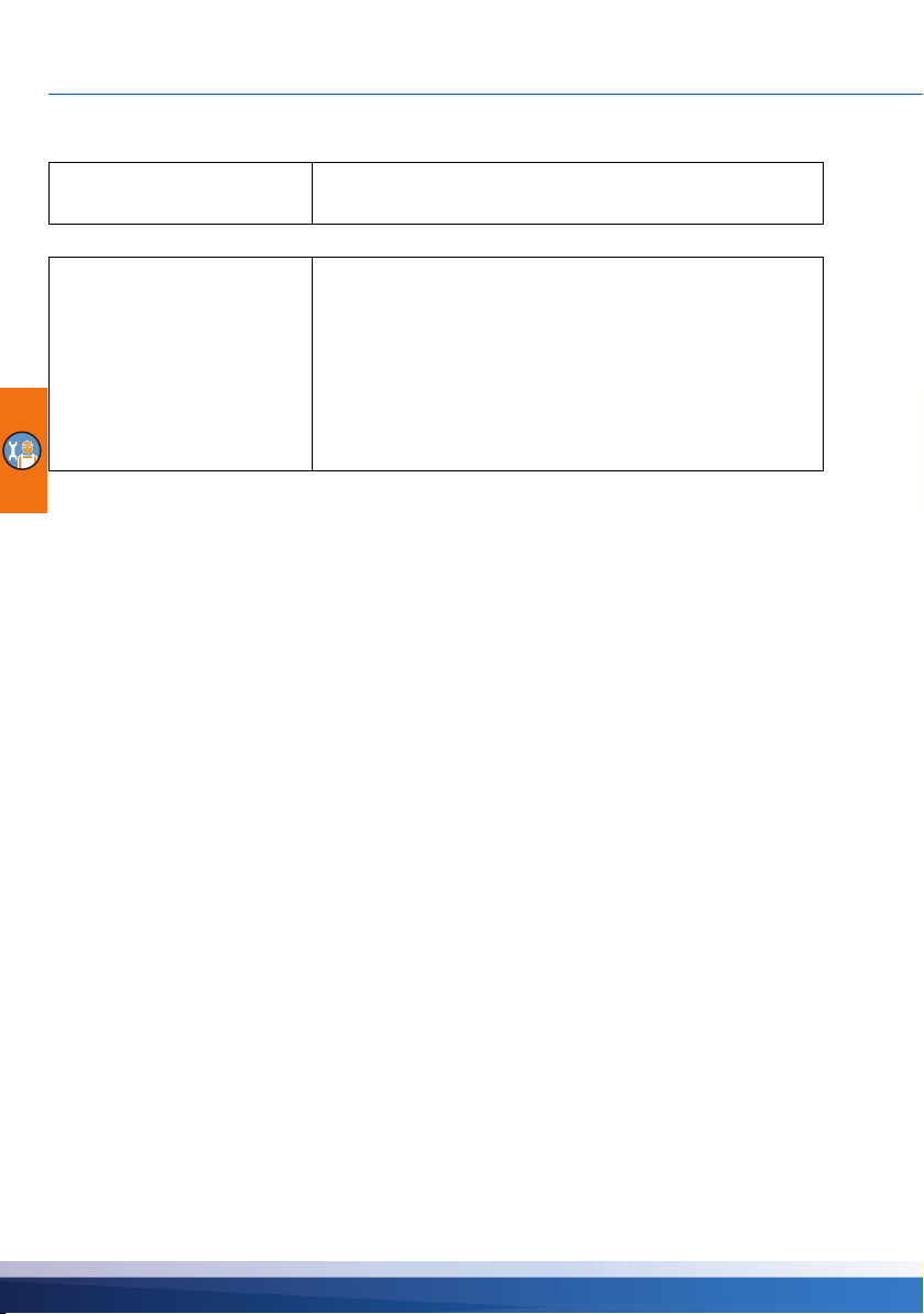
SETTINGS IN THE PROFESSIONAL MODE
NOTICE
NOTICE
Two files are generated by the update process on the Micro SD card: RESULTS.TXT which contains
the result of each update process and UPDLOGS.TXT which shows the software version after the
update.
Nothing should interrupt the update process, especially no
power loss!
If the update has not begun within one minute after the selection of ›Firmwareupdate SD‹, the controller will restart.
If the update process is aborted, and so the controller is not
ready for operation, it must be switched off. (Disconnected
from the mains.)
When switching it on again, press the esc button until the display flashes.
The update process can now be repeated.
66 smart Stove - 0142 - 42WMSUGAT2-C
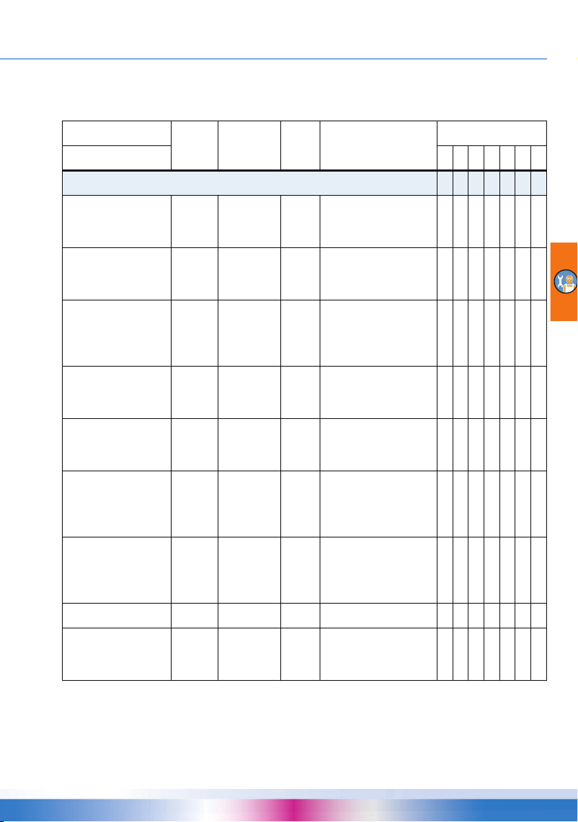
SETTINGS IN THE PROFESSIONAL MODE
Summary of parameters in ›Basic functions‹
Items marked by an asterisks * are only available in professional mode.
Menu/parameter Default Range Unit Description Hydraulic system
Basic functions
Control parameters
Add. heat enabled Yes No/Yes
Charge start 58 30 ... 90 °C
Charge offset * 5 2 ... 15 K
Act. ZV below * 43 20 ... 90 °C
Offset ZV act. * 2 1 ... +10 K
Ext. AH pump On * 5 1 ... 5 K
Ext. AH pump Off * 2 -5 ... +2 K
DPD * 0 0 ... 50 min*K
High. imm. heater * No No/Yes
Recharging of the
tank by the additional
heating
Minimum stove temperature for starting
the loading pump
Temperature offset for
starting the speed
control of the loading
pump
Lower temperature
threshold for activa
tion of zone valve
Temperature offset
(hysteresis) for zone
valve activation
Switch-on temperature offset (hysteresis)
for additional heating
pump
Switch-off temperature offset (hysteresis)
for additional heating
pump
Dynamic pump delay x x x
Force start and stop
sensor to TS2 for
additional heating
1 2 3 4 5 6 7
x x x x x x x
x x x x x x x
x x x x x x x
x x x
x x x
-
x x x
x x x x x x x
x
x
smart Stove - 0142 - 42WMSUGAT2-C 67

SETTINGS IN THE PROFESSIONAL MODE
Menu/parameter Default Range Unit Description Hydraulic system
Basic functions
Common Eco/Comf * Yes No/Yes
fix PWM * 30 5 ... 100 %
Min control PWM * 30 5 ... 100 %
Step PWM * 5 2 ... 10 %/K
Domestic hot water
Req. add. heat 50 20 ... 90 °C
Offset add. heat * +5 1 ... +20 K
Req. st ove 55 20 ... 90 °C
Offset stove * +10 1 ... +50 K
Disable or enable the
›Operation mode‹ dis
play (during commissioning only)
Fixed PWM speed of
high efficiency pump
for loading domestic
hot water/external AH
Lower PWM speed
level for controlling
the stove charging
pump
PWM pump speed
increment
Setpoint for request
for heat from stove
with additional heat
ing. If the tank temperature falls below this
temperature the
request will be acti
vated.
Offset for deactivating request for heat
from stove with addi
tional heating
Setpoint for request
for heat from stove. If
the tank temperature
falls below this tem
perature the request
will be activated.
Offset for deactivating request for heat
from stove
1234567
x x x x x x x
-
x x x
x x x
x x x
x x x x x x x
x x x x x
-
-
x x x x x
-
x x x x x x x
-
x x x x x x x
68 smart Stove - 0142 - 42WMSUGAT2-C
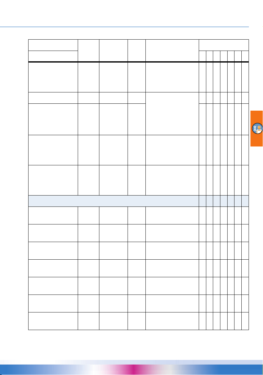
SETTINGS IN THE PROFESSIONAL MODE
Menu/parameter Default Range Unit Description Hydraulic system
Basic functions
Max. temp DHW * 60 20 ... 90 °C
Charge diff DHW * 3 1 ... 5 K
Charge hys DHW * 6 2 ... 10 K
DRD DHW Eco 100 0 ... 500 min*K
DRD DHW Comf 0 0 ... 500 min*K
Anti-legionellae *
Activation * Yes No/Yes
Targe t t e m p * 60 55 ... 85 °C
Hysteresis * 3 1 ... 5 K
Start time * 3 0 ... 23 hour
Duration * 10 5 ... 60 min
Max. time * 48 4 ... 96 h
Use add. heat * Yes No/Yes
Maximum temperature for external
domestic hot water
tank
Control of the pump
for domestic hot water
with conditions:
TS2 > TS5 +
Charge diff DHW and
TS5 < Max. temp DHW –
Charge hys DHW
Dynamic recharge
delay for domestic hot
water heating - econ
omy mode
Dynamic recharge
delay for domestic hot
water heating heating
- comfort mode
Activation of anti-legionella function
Target temperature for
disinfection
Temperature hysteresis for switch-on
Starting time for heating
Duration of the
required heating cycle
Maximum heating
period (timeout)
Use additional heating
for disinfection
1234567
x x
x x
x x
x x x x x
-
x x x x x
x x x x x x x
x x x x x x x
x x x x x x x
x x x x x x x
x x x x x x x
x x x x x x x
x x x x x x x
x x x x x x x
smart Stove - 0142 - 42WMSUGAT2-C 69
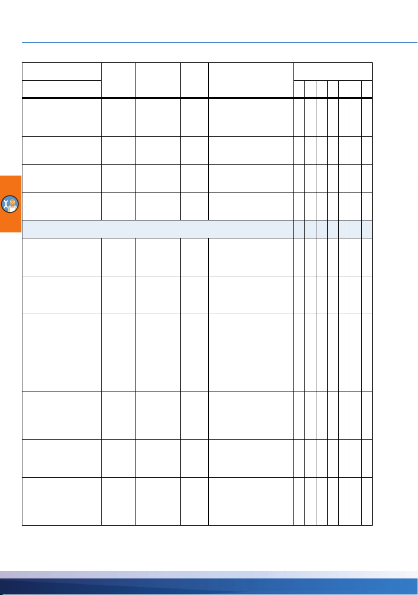
SETTINGS IN THE PROFESSIONAL MODE
Menu/parameter Default Range Unit Description Hydraulic system
Basic functions
Delay add. heat * 72 0 ... 96 h
Day * Friday Monday ...
Interval * 7 1 ... 14 days
Allow any heat * Ye s No/Yes
Space heating
Block SH below * 43 20 ... 90 °C
Offset SH block * 2 1 ... +10 K
Req. add. heat 50 20 ... 90 °C
Offset. add. heat * +5 1 ... +20 K
Req. st ove 55 20 ... 90 °C
Offset stove * +10 1 ... +50 K
Sunday
day
Time delay for heating
cycle with additional
heating
Day of week for disinfection
Repetition interval for
disinfection
Use any heat source
for disinfection
Tank temperature for
blocking space heat
ing
Temperature offset
(hysteresis) for block
ing space heating
Setpoint for request
for heat from addi
tional heating. If the
tank temperature falls
below this tempera
ture the request will
be activated
Offset for deactivating request for heat
from additional heat
ing
Required tank temperature for space heating with stove
Tank temperature offset (hysteresis) for
space heating with
stove
1234567
x x x x x x x
x x x x x x x
x x x x x x x
x x x x x x x
x x x x x x x
x x x x x
-
x x x x x
-
x x x x x
-
-
x x x x x
-
x x x x x x x
x x x x x x x
70 smart Stove - 0142 - 42WMSUGAT2-C

SETTINGS IN THE PROFESSIONAL MODE
Menu/parameter Default Range Unit Description Hydraulic system
Basic functions
DRD SH Eco 100 0 ... 500 min*K
DRD SH Comf 0 0 ... 500 min*K
Stop sensor *
AH DHW Eco * TS 2 TS 2 ... TS 4
AH DHW Comf * TS 2 TS 2 ... TS 4
Stove DHW Eco * TS 3 TS 3 ... TS 4
Stove DHW Comf * TS 3 TS 3 ... TS 4
AH SH Eco * TS 2 TS 2 ... TS 4
AH SH Comf * TS 3 TS 3 ... TS 4
Stove SH Eco * TS 3 TS 3 ... TS 4
Dynamic recharge
delay for space heat
ing - economy mode
Dynamic recharge
delay for space heat
ing - comfort mode
Temperature sensor
for domestic hot water
with additional heating
in economy mode
Temperature sensor
for domestic hot water
with additional heating
in comfort mode
Temperature sensor
for domestic hot water
with stove in economy
mode
Temperature sensor
for domestic hot water
with stove in comfort
mode
Temperature sensor
for space heating with
additional heating in
economy mode
Temperature sensor
for space heating with
additional heating in
comfort mode
Temperature sensor
for space heating with
stove in economy
mode
1234567
x x x x x
-
x x x x x
-
x x x x x x x
x x x x x
x x x x x
x x x x x x x
x x x x x x x
x x x x x
x x x x x
x x x x x x x
smart Stove - 0142 - 42WMSUGAT2-C 71

SETTINGS IN THE PROFESSIONAL MODE
Menu/parameter Default Range Unit Description Hydraulic system
Basic functions
Stove SH Eco Comf * TS 3 TS 3 ... TS 4
Allow TS4 * No No/Yes
Temperature sensor
for space with stove
heating in comfort
mode
1234567
x x x x x x x
x x x x x x x
72 smart Stove - 0142 - 42WMSUGAT2-C

Malfunction
System 1
17.03.2016 12:14
The differential temperature controller smart Stove indicates faults.
The “Attention” symbol appears at the top right corner of the
display.
A symbol indicates that there is a fault and the controller is in
failure operation.
To start the ›Service Wizard‹, press the knob.
MALFUNCTION
NOTICE
If a malfunction message appears in the display, the operator
can define the possible causes by means of the ›Service
Wizard‹ so that he/she can provide the installer with precise
information.
There may be various deficiencies in a thermal system, which
require a wide variety of approaches. The controller communi
cates every step to the operator or installer via the screen, so
that there is no need to describe all malfunctions in detail in
this operating manual.
-
DANGER
Repair or disassembly
Lethal danger due to electrocution!
For troubleshooting on the plant, disconnect all poles of the
power supply reliably and protect it them against being
switched on again!
Sensor monitoring
The temperature sensors TS1 to TS6 are monitored for short-circuit or interruption. A sensor fault
(interruption or short-circuit) is indicated in the model diagram by three minus signs:
The controller has stored temperature limits which comprise the temperature range that is usually to
be expected for a heating control. If this range is left, the controller signals an error.
In case of use of PT1000 sensors, the following limits have been established:
• Short-circuit: Measured temperature ‹ -30°C (resistance ‹882 )
• Interruption: Measured temperature › 250 °C (resistance ›1.931 )
“---”.
smart Stove - 0142 - 42WMSUGAT2-C 73

MALFUNCTION
1.10 Service Wizard
17.03.2016 12:14
M50
Overload of fuel
in stove!
Menu Next
1.10 Service Wizard
17.03.2016 12:14
M02:
Breakage of
sensor on TS1!
Menu Next
1.10 Service Wizard
17.03.2016 12:14
M02:
Breakage of
sensor on TS1!
Menu Next
1.10 Service Wizard
17.03.2016 12:14
Possible reasons:
Cable/connection
Sensor
Exit
Service Wizard
The ›Service Wizard‹ indicates the possible causes of malfunctions on the basis of the detected
symptoms and thus supports immediate and comfortable detection of deficiencies.
Example for protective function
If ›Safety function‹ appears in the display, this is a message,
no malfunction.
In this case, there is no fault, but limits have been exceeded.
The controller indicates that a protective function has been
triggered.
The message is only active until normal operation has been
restored.
Example for malfunction
Here, a malfunction message with troubleshooting process is presented as an example.
›1.10 Service Wizard‹ appears.
The malfunction appears in plan text - here:
›M02: Breakage of sensor on TS1!‹.
If an analysis/repair is not required at present, press ›Menu‹ to
return to the main menu.
The Service Wizard helps detect possible causes of malfunctions.
Acknowledge by selecting ›Next‹.
For this malfunction, the following causes are assumed:
›Cable/connection‹ or ›Sensor‹ -
Select the first menu item and confirm by pressing the knob.
74 smart Stove - 0142 - 42WMSUGAT2-C

MALFUNCTION
1.10 Service Wizard
17.03.2016 12:14
Please check the
connection cable
to the sensor
Next
1.10 Service Wizard
17.03.2016 12:14
Disconnect it
and measure
its resistor.
Next
1.10 Service Wizard
17.03.2016 12:14
Could you detect
a short-circuit /
cable break?
No Yes
1.10 Service Wizard
17.03.2016 12:14
Please replace
the cable.
Exit
1.10 Service Wizard
17.03.2016 12:14
Could you detect
a short-circuit /
cable break?
No Yes
The controller here provides the troubleshooting instruction to
check the connection cable.
Perform the measure in accordance with the recommendation.
Acknowledge by selecting ›Next‹.
More detailed instructions are available if required.
Acknowledge by selecting ›Next‹.
The troubleshooting result is interrogated.
Continue via ›Yes‹ for the case that the malfunction has been
determined.
Repair information appears.
Perform the appropriate repair work.
Exit the ›Service Wizard‹ by pressing ›Exit‹.
f the cause of the malfunction has not yet been determined,
troubleshooting can be continued.
Continue with ›No‹.
smart Stove - 0142 - 42WMSUGAT2-C 75
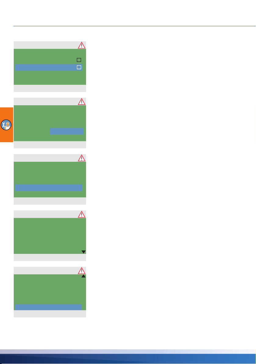
MALFUNCTION
1.10 Service Wizard
17.03.2016 12:14
Possible reasons:
Cable/connection
Sensor
Exit
1.10 Service Wizard
17.03.2016 12:14
Please check
the sensor for
plausible values.
Explanation
1.10 Service Wizard
17.03.2016 12:14
Disconnect it
and measure
its resistor.
Next
1.10 Service Wizard
17.03.2016 12:14
With PT 1000 sensors
0°C to 100°C
correspond to
a resistor of
1000 to 1385 Ohm.
1.10 Service Wizard
17.03.2016 12:14
Is your measured
value within
this range?
Yes
No
Select all the sources of malfunctions listed, and confirm.
Appropriate instructions appear for each source of faults.
Perform the measure in accordance with the recommendation.
Continue with ›Explanation‹.
A part of the information and instructions may be provided in
close detail, so that ...
...the texts may well take several screens.
After description of the troubleshooting measure, the result
determined by you is interrogated...
76 smart Stove - 0142 - 42WMSUGAT2-C

MALFUNCTION
1.10 Service Wizard
17.03.2016 12:14
Sensor is faulty and
must be replaced.
Exit
System 1
17.03.2016 12:14
... and the appropriate logical conclusion is made, the repair
work displayed.
After elimination of the malfunction, the plant screen without
the ”Attention” symbol appears again on the display, automatic
mode is continued.
smart Stove - 0142 - 42WMSUGAT2-C 77

REPLACEMENT OF FUSE
Replacement of fuse
DANGER
Repair or disassembly
Lethal danger due to electrocution!
Before opening the terminal cover, disconnect all poles of the
power supply reliably and protect it them against being
switched on again!
To remove the device fuse, open the terminal cover.
Above the right-hand group of terminals, the fuse base and a spare fuse are located. Pull the upper
part of the support and the spare part out.
The glass tube fuse is clamped in the formed piece and is removed together with the plastic holder.
78 smart Stove - 0142 - 42WMSUGAT2-C

DANGER
Wrong fuse type used.
Risk of fire due to overload or short-circuit!
Only use glass tube fuses type 5 x 20 mm, T2A!
Now, push the micro-fuse laterally out of its holder.
The glass tube fuse is installed by reversing the above order.
Make sure to procure yourself immediately a new spare fuse!
REPLACEMENT OF FUSE
smart Stove - 0142 - 42WMSUGAT2-C 79

TECHNICAL DATA
Technical data
Differential temperature controller smart Stove
Type of mounting Wall-mounting
Housing Plastics, in several parts
Mode of operation Type 1
Type of protection IP 20
Dimensions Width x Height x Depth [mm] 115 x 173 x 46
Weight [g] Basic version 370
Storage/operating temperature [°C] 0-40, non-condensation
Handling via knob and push buttons
Display TFT colour display 47 x 35 mm, backlit
Power reserve of real time clock, at least [h] 8
Connection to power supply
Design 3 spring-type terminals PE, N and L
Operating voltage [VAC] 230 ±10%
Line frequency [Hz] 50 ±1%
Auxiliary consumption typ. [W] 1.74
Power consumption max. [W] 3.5
Fuse Micro fuse, type 5 x 20 mm, T2A/250 V
Rated pulse voltage [V] 2500
Max. cross sections to be connected
Cable end sleeve: 0.25 to 0.75 mm
Single-wire 0.50 to 1.50 mm
Fine-wired 0.75 to 1.50 mm
2
2
2
Interfaces TS1 / TS2 / TS3 / TS4 / TS5 / TS6
Design 2 spring-type terminals each
Assignment as inputs Temperature sensor Pt 1000
Admissible temperature sensor
80 smart Stove - 0142 - 42WMSUGAT2-C

TECHNICAL DATA
Interface TS7 / TS8
Design 2 spring-type terminals each
Assignment as output PWM signal 100 Hz...2 kHz or
analogue output 0...10 V, max. 10 mA
Triac outputs RO1 / RO2
Design 3 spring-type terminals each, PE, N and L
Output voltage [VAC] 230 ±10%
Output power max. per output [VA] 200
Output current max. per output [A] 1
Switching output REL: change-over contact
Design 3 spring-type terminals
Switching voltage max. [V] 253
Switching capacity max. [VA] 230
Switching current max. [A] 1
Interface for analogue Vortex flow sensors
Design Plug connector
smart Stove - 0142 - 42WMSUGAT2-C 81

DISASSEMBLY/DISPOSAL
Disassembly/disposal
DANGER
Disassembly
Lethal danger due to electrocution!
Before opening the terminal cover, disconnect all poles of the
power supply reliably and protect it them against being
switched on again!
For disassembly of the differential temperature controller smart Stove, reverse assembly procedure:
- Disconnect the power supply.
- Open the terminal cover.
- Disconnect all cables.
- Release the wall screw fastening.
- Remove the controller from its mounting location.
DANGER
Loose cables
Lethal danger due to electrocution!
When removing the controller, secure all stripped cable ends
so that they cannot be touched by persons!
Remove cables completely on definite removal.
NOTICE
The person who or the institute which is responsible for disposal of the device must not discard the controller with the
residual waste, but must ensure correct recycling in accor
dance with the local provisions!
In case of doubt, ask the local disposal company or the authorized dealer from which you have purchased the device.
82 smart Stove - 0142 - 42WMSUGAT2-C
-

WARRANTY AND LIABILITY
Warranty and liability
The differential temperature controller smart Stove was developed, manufactured and tested
according to stringent quality and safety specifications and corresponds to the state of the art.
The device is subject to the warranty period prescribed by law of 2 years after the date of sale.
The seller shall eliminate all defects in material and workmanship which occur on the product during
the warranty period and which impair the product‘s functionality.
Natural wear and tear does not constitute a defect.
Warranty and liability does not include all damage which is due to one or several of the following
reasons:
• Non-compliance with these Assembly and Operating Instructions.
• Inappropriate transport.
• Faulty assembly, commissioning, maintenance or operation.
• Modifications of the structure or tampering with the software of the device.
• Installation of supplementary components which are not approved by the manufacturer.
• Continued use of the controller despite an obvious defect.
• Use of non-approved spare parts and accessories.
• Applications exceeding the intended scope of utilization.
• Inappropriate utilization of the device / improper handling, e. g. ESD.
• Use of the device outside of the admissible technical boundaries.
• Voltage surges, e. g. due to lightning strokes.
• Force majeure.
Further claims based on this warranty obligation, especially compensation for damage exceeding
the asset value of the differential temperature controller, are excluded.
Construction, design and project engineering of heating installations are performed by specialist
installers based on the applicable standards and directives.
The functioning and safety of a plant are the exclusive responsibility of the companies commissioned with planning and execution.
Contents and illustrations of this manual have been elaborated to the best of our knowledge and
with utmost diligence - we reserve the right of error and technical modifications.
Liability of the manufacturer for inappropriate, incomplete or incorrect information and all damage
resulting therefrom is excluded on principle.
smart Stove - 0142 - 42WMSUGAT2-C 83

COMMISSIONING REPORT
Commissioning report
Name of operator and place of installation:
Date of commissioning:
Installed hydraulic system:
Make and serial number of stove:
Tank sizes [l]:
Particularities:
The wood log or pellet stove with the differential temperature controller smart Stove has been
installed and commissioned in an expert fashion.
The owner / operator of the plant was informed in detail and instructed as regards the design, operation, handling, especially in connection with the differential temperature controller smart Stove.
Commissioning by the company (name/address/telephone number):
Name of employee:
84 smart Stove - 0142 - 42WMSUGAT2-C

Service request
Error pattern/error description:
Error message:
Software version:
Readings: TS1:
TS2:
TS3:
TS4:
TS5:
TS6:
Wiring: RO1: Pump HE Valve
RO2: Pump HE Valve
REL: Ye s No
Service hours: RO1:
RO2:
REL:
Equipment/Accessories/Options:
SERVICE REQUEST
NOTICE
For repair or replacement of the controller, make sure that
completed copies of the commissioning report and of the error
report are included!
smart Stove - 0142 - 42WMSUGAT2-C 85

CE DECLARATION OF CONFORMITY
CE declaration of conformity
The manufacturer
emz-Hanauer GmbH & Co.KGaA
Siemensstraße 1
D - 92507 Nabburg
declares in its sole responsibility that the following product:
Differential temperature controller smart Stove
to which this Declaration refers, complies with the following directives and standards:
Directive 2006/95/EC of the European Parliament and the Council dated 12 December
2006 on the harmonization of the laws of the Member States relating to electrical equip
ment designed for use within certain voltage limits.
Directive 2004/108/EC of the European Parliament and the Council dated 15 December
2004 on harmonization of the laws of the Member States relating to electromagnetic
compatibility and abolition of the Directive 89/336/EEC.
Directive 2001/95/EC of the European Parliament and of the Council dated 3 December
2001 regarding general product safety.
Technical regulations, Low-Voltage Directive:
• EN 60730-1:2000 + AC:2007
• Technical regulations, EMC Directive:
• EN 60730-1:2000 + A1:2004 + A12:2003 + A13:2004 + A14:2005 (EMC part)
• EN 55022:1998 + Corr. 1999 (Class B)
• EN 61000-3-2:1995 + corr. July 1997 + A1: 1998 + A2:1998 + A14:2000
• EN 61000-3-3:1995 + A1:2001 + A2:2005
-
D - 92507 Nabburg, 29.04.2013,
Signed by:
Thomas Hanauer pp Josef Irlbacher
Managing Director Head of the Electronic Development Team
86 smart Stove - 0142 - 42WMSUGAT2-C

INDEX
Index
A
About 39
Access code 38, 54
Active system 13
Additional heating 26
Anti-blocking 63
Antifreeze 63
Antifreeze protection 26
Anti-legionella
function 26
parameters 60
Anti-legionellae 55
Automatic mode 30
Automatic operation 30
B
Basic functions 36, 55
Basic settings 50
Boiler 16
Boiler connection
to REL 47
Breakage of sensor 74
Break-out segments 43
Brightness 35
Buzzer 35
C
Cable cross sections 80
Cable preparing 45
CE declaration of conformity 86
Check box 15
Checklist 51
Choose system 51
Cleaning 8
Comfort mode 14
Commissioning 50, 55, 57
date 39
Commissioning mode 50
Commissioning report 84
Common mode 14
Communication screen 14
Components 43
Conditions of use 7
Connection 9, 44
Control elements 12
Cooling 28
Cross sections
of cables 80
D
Data interfaces 10
Data logging 11
Date 13, 15
setting 50
Description 9
Dimensions 40
Disassembly 82
Display 12, 13, 43
Disposal 82
Domestic hot water 37, 55
indication 13
DPD 24
DRD 26
Dynamic pump control 24
Dynamic pump delay 24
Dynamic recharge delay 26
E
Economy mode 14
Electrical connection 44
Error list 33, 38
esc button 12, 43
operating 13
Evaluation 32, 55
Existing configuration
loading 51
Ext. heat blocking connection
to REL 48
Ext. heat connection
to REL 47
F
Factory settings 36
Fire detection 24
with pellet stove 24
Firmware update 65
Firmwareupdate SD 65
Fuse 43, 80
replacement 78
H
Hardware version 39
Heating 28
High-efficiency pump 48
smart Stove - 0142 - 42WMSUGAT2-C 87

INDEX
Housing base 43
Housing cover 43
Hydraulic symbols 16
Hydraulic systems 16
I
Impeller sensor 80
Information screen 13
Intended use 8
Interfaces 80
Interruption 73
K
Knob 12, 43, 80
operating 12
L
Language
changing 35
setting 50
Legend
of hydraulic symbols 16
Liability 83
Limits 63
for overtemperature protection 64
Load existing configuration 51
Login 38, 54, 65
M
Main menu 32, 54
Malfunction 73
Manual mode 15, 65
Maximum switching capacity 46, 47, 48
Menu structure 31
Menus 31
Message 15
Micro SD
firmware update 65
Micro SD card 10
remove safely 36
Mixing valve 16
Monitoring 38, 64
Mounting 9, 40
O
OK button 12, 43
Opening 40
Operation 12
settings 31
Operation mode 13
Outdoor temperature sensor 16
Output parameter 55, 56
Overtemperature protection 25
limits 64
P
Parameters
summary 67
Pellet stove 16
fire detection 24
Power supply 80
Professional mode 15
settings 54
Protective functions 63
Pt 1000 9, 80
Pump 16
Pump blocking connection
to REL 47
to RO2 48
Pump connection
to REL 46
Pump monitoring 64
Pump speed 24
PWM signal 48
R
REL
boiler connection 47
ext. heat blocking connection 48
ext. heat connection 47
pump blocking connection 47
pump connection 46
zone valve connection 46
Relay
maximum switching capacity 46, 47, 48
Remove SD card safely 36
Request for heat 27
Request for heat connection
to RO1 48
Return line 16
RO1
request for heat connection 48
zone valve connection 46
88 smart Stove - 0142 - 42WMSUGAT2-C

INDEX
RO2
pump blocking connection 48
S
Safety information 7
Save parameter 36
Scope of supplies 9
Screw connection 43
Screw fastening 43
Scroll arrow 15
SD
firmware update 65
SD card 10
remove safely 36
Sensor
breakage 74
connection 9
type 9, 80
Sensor balancing 64
Sensor monitoring 73
Separate mode 14
Serial number 39
Service request 85
Service Wizard 74
Settings 34, 55
during operation 31
in the professional mode 54
Short-circuit 73
Software version 39
Space heating 55
indication 13
Spare fuse 43
Stop sensor 55
Stove control 24
Strain relief device 43
Submenu 15
Summary
of parameters 67
Supply line 16
System 13, 39
choosing 51
Temperature sensor 16
connection 9
monitoring 73
type 9, 80
Temperature thermostat 28
Terminal cover 40, 43
Terminals 43, 44
Thermostat 55, 56
activation 36
Thermostat functions 28
Time 13, 15
setting 50
Timer function 28
Timer thermostat 29
U
USB
connection symbol 15
USB port 10
V
Vortex plug connector 43
W
Wall-mounting 41
Warranty 83
Window 29
Wood log stove 16
Z
Zone valve 16
connection to REL 46
connection to RO1/RO2 46
T
Tank 16
Technical data 80
Temperature comparator 29
smart Stove - 0142 - 42WMSUGAT2-C 89

emz-Hanauer GmbH & Co. KGaA
Siemensstraße 1
D-92507 Nabburg
Tel.: +49 (0) 9433 898-0 info@emz-hanauer.com
Fax: +49 (0) 9433 898-188 www.emz-hanauer.com
Edition EN 03/2016
0142 - 42WMSUGAT2-C
 Loading...