


Equipment ›Excellence‹

These Assembly and Operating Instructions are an integral part of the product.
> Read Assembly and Operating Instructions carefully before using the product.
> Keep them in a safe place during the product‘s service life.
Translation from the German original edition ©emz 2012 - Subject to modications.
The contents and representations of these Assembly and Operating
Instructions are the intellectual property of emz-Hanauer GmbH & Co.KGaA.
Non-authorized disclosure, reproduction, divulgation or editing of this
documentation, as well as exploitation, utilization or publication, are prohibited.
The rights to the word and design marks ›emz - smart solutions‹ and ›smart Sol plus‹
are the exclusive property of emz-Hanauer GmbH & Co.KGaA.
The rights to any cited brands, names or logos are the property
of their appropriate developers / of the licensees in question.

3
Table of Contents
Table of contents Page
Important fundamental information 4
Symbols used 5
Description 6
Dimensions 7
Technical Data 8
Designation of the components 10
Operation of the controller 11
Display 12
Opening the terminal cover 13
Wall-mounting 14
Connection to power supply 15
Data interfaces 19
Hydraulic systems 20
Functions for boiler control 51
Thermostat functions 54
Soft water station AQA solar 55
Commissioning mode 57
Automatic mode 63
Operation mode 64
Malfunction 78
Replacement of fuse 85
Professional mode 86
Disassembly/Disposal 107
Warranty and liability 108
Error report 109
EC Declaration of conformity 111
Index 112

4
Important fundamental information
These instructions describe installation, commissioning, operation, repair
and disassembly of the differential temperature controller smart Sol plus for
solar thermal plants.
For operation of the entire plant, the technical documentation of all the
components used such as solar collectors, boiler, tank, pumps, mixers
and valves etc. must be complied with.
The controller is handled by the operator of the entire solar
thermal plant, i. e. as a rule by technical non-experts.
Make sure not to use the controller until you have thoroughly read and
understood these Assembly and Operating Instructions and the safety provisions.
Comply with all safety provisions and involve a specialist in case of doubt.
Keep these Assembly and Operating Instructions and all reference
documents so that they are available if required.
When relocating or when selling the device, hand the documents over to your successor.
Important!
The tter installing the controller must inform the plant operator about
operation, functioning and the method of action of the smart Sol plus!
Danger!
The device in operation may only be made accessible to
adults disposing of appropriate knowledge and experience!
Danger!
The controller by no means replaces the safety
components required under plant engineering aspects!
Danger!
Assembly, connection, commissioning, repair and disassembly of
the controller may only be performed by a qualied specialist!

5
Symbols used
When handling the differential temperature controller smart Sol plus
and the entire plant, please make sure that the following safety provisions
in the Assembly and Operating Instructions are complied with!
Note!
Useful information regarding handling of the device and the plant!
Important!
Important information compliance with which is essential!
Danger!
Immediate danger for assets, life and limb!

6
Description
The differential temperature controller smart Sol plusis an independent electronic
controller for surface-mounting which is used for the control of solar thermal plants.
The controller is equipped with a robust three-part plastic housing
which can only be opened by means of tools (screw driver PH2).
Operation is effected by means of only two control elements;
indications appear against a backlit colour display.
Before connection of the electrical system, the controller
must be mounted rmly to a perpendicular, robust surface (wall).
For its own supply and the supply of the outputs, the controller must be connected
to an electrical energy supply system in accordance with the technical data.
Assembly, connection, commissioning, repair and disassembly
of the controller are only admissible in a specialist workshop.
To ensure correct operation, temperature sensors type Pt 1000
must be used - the sensor design does not affect function.
Each temperature sensor has two connectors which are equivalent,
i. e. interchangeable. Thus, polarity reversal is not an issue.
The sensor lines can be extended up to a length of 100 m, to
this effect, a cable cross section of 2 x 1.5 mm2 is recommended.
Note!
The electrical equipment of the device must be installed rmly and
connected to the power supply via a disconnector ensuring complete
isolation from the power supply according to the erection regulations!
Important!
Make sure that only a dry or slightly moistened cloth is used for cleaning
and servicing of the housing, the control elements and the display.
The surfaces must never get into contact with cleaning products
or solvents - mat, brittle or slightly dissolved plastic parts must
be replaced immediately!
A device with damaged housing must not be operated!

7
Dimensions
218 mm 51 mm
109 mm
d
max
5/9 mm
109 mm
140 mm
30 mm
48 mm
218 mm
5 mm

8
Technical Data
Intended Use
The differential temperature controller may be used exclusively as controller for the con-
trol of solar thermal plants. It must be operated within the scope of all the specications
described. Installation and set-up of the controller may only be performed by specialists.
The tter must have read and understood the operating manual.
The tter explains all the relevant functions to the operator.
For operation, it is essential that the housing is closed and free of damage.
Scope of supplies
1 Differential temperature controller smart Sol plus
1 Instruction manual
Differential temperature controller smart Sol plus
Type of mounting Wall-mounting
Housing Plastics, in several parts
Mode of operation Type 1
Type of protection IP 20
Dimensions Width x Height x Depth [mm] 218 x 218 x 51
Weight [g] Basic version 725
Storage/operating temperature [°C] 0-40, non-condensation
Handling via rotary encoder and pushbuttons
Display TFT colour display 70 x 53 mm, backlit
Connection to power supply
Design 3 spring-type terminals PE, N and L
Service voltage [VAC] 85-265
Line frequency [Hz] 50 ±1%
Auxiliary consumption typ. [W] 1.25
Power consumption max. [W] 3.1
Fuse Micro fuse, type 5 x 20 mm, T4A/250 V
Rated pulse voltage [V] 2500
Max. cross sections to be connected
Cable end sleeve: 0.25 to 0.75 mm
2
Single-wire 0.50 to 1.50 mm2
Fine-wired 0.75 to 1.50 mm
2

9
Technical Data
Interfaces TS1 - TS8
Design 2 spring-type terminals each
Assignment as inputs
Admissible temperature probe Temperature sensor Pt 1000
Optional assignment of
TS6-TS8 to the impeller sensor DFZ 1-100 pulses/litre
Optional assignment as PWM signal 100Hz...2kHz or
output on TS7/TS8 analogue output 0...10V, max. 10mA
Interfaces TS9 - TS10
Design 2 spring-type terminals each
Assignment to the impeller sensor DFZ 1-100 pulses/litre
Assignment as output PWM signal 100Hz...2kHz or
analogue output 0...10V, max. 10mA
Active outputs RO1-RO4 :Triac outputs
Design 3 spring-type terminals each, PE, N and L
Output voltage [VAC] 85-265
Output power max. per output [VA] 200
Output current max. per output [A] 1
Switching output REL: Floating change-over contact
Design 3 spring-type terminals
Switching voltage max. [V] 253
Switching capacity max. [VA] 230
Switching current max. [A] 1
Interface for analogue Vortex ow sensors
Design 1 multi-pin connector
5V/24V supply terminals
Design 1 spring-type terminal each
Output voltage [VDC] 5V/24V
Max. current per output [mA] 15
Supply terminals L
Design 1 spring-type terminal each
Output voltage [VAC] 85-265
The total current of all outputs including RO1-RO4 must not exceed 4A!
10
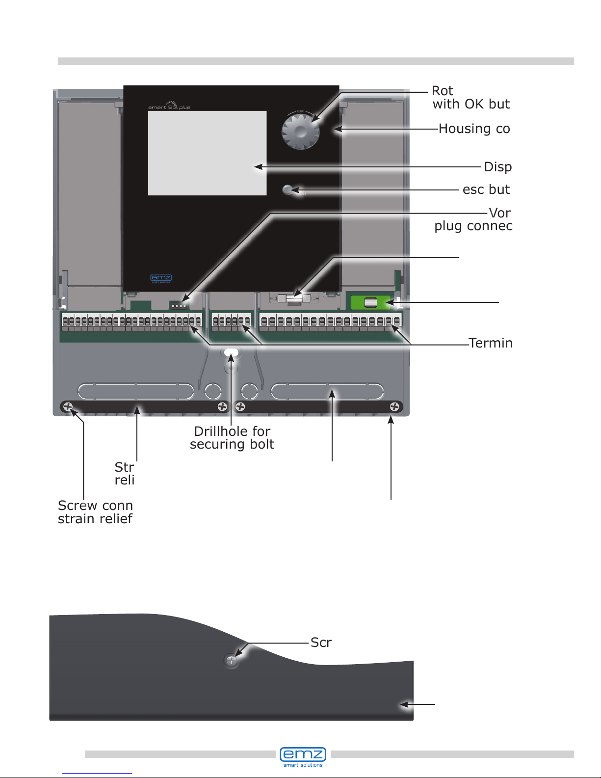
Designation of the components
Housing
base
Drillhole for
securing bolt
Vortex
plug connector
esc button
Display
Rotary encoder
with OK button
Housing cover
Screw fastening of terminal cover
Break-out
segments
Screw connection
strain relief device
Strain
relief device
Terminal cover
Terminals
Fuse
Spare fuse
11
Operation of the controller
The entire set-up and operation of the differential temperature controller
smart Sol plus is effected via only two control elements on the device front.
All settings and interrogations are effected via the rotary encoder.
To nd a required menu item, turn the rotary encoder to ›scroll‹
through the menu - the selectable option appears on a coloured
background on the display.
To conrm the selected menu item, press the rotary encoder.
An appropriate submenu is called up, or selection is activated.
Press the esc button to make the menu return by one level from any subitem.
If no input is made within the preset time (30-255 s),
the controller returns automatically to the initial level.

12
Activation
Start
t ON
T ON
t solar 1
n solar 1
t solar 2
10min
20.0°C
20s
100%
0s
1.3.2 Tube collector
25.08.2012 10:35
System 11
25.08.2012 10:35
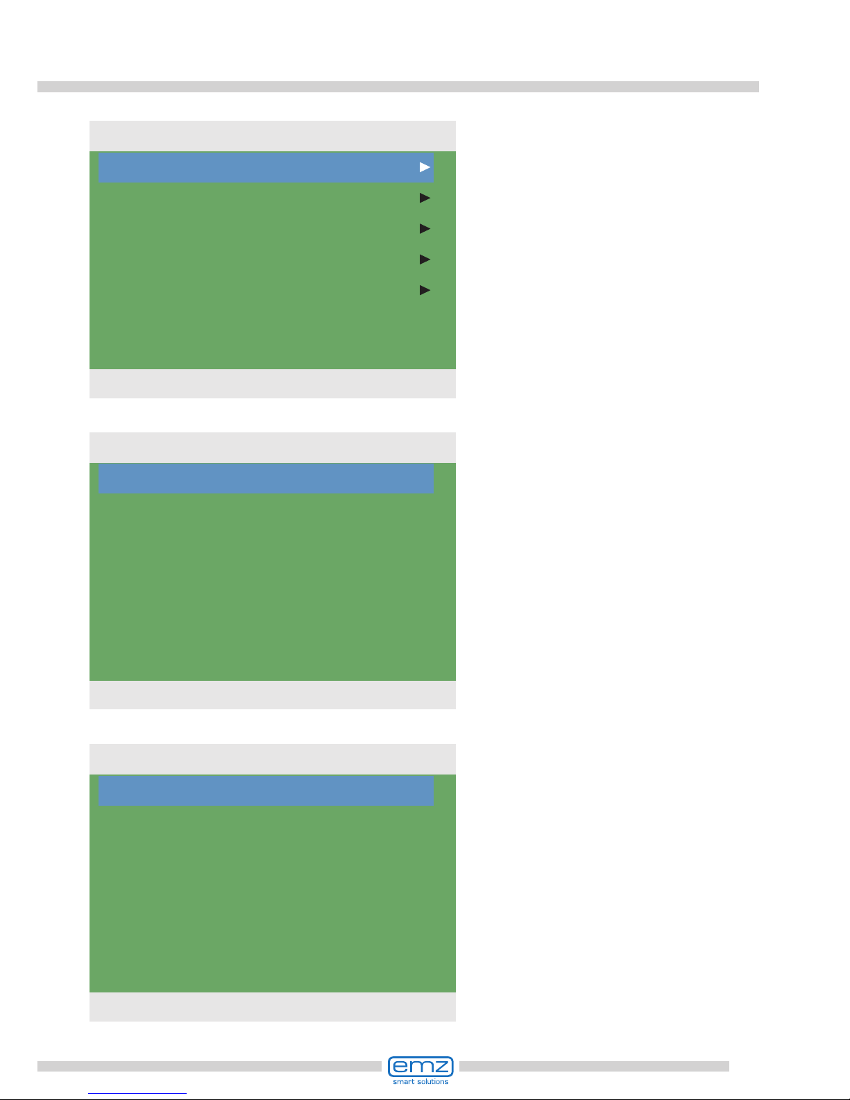
Display elements; example: information screen
Display
For indication of the operating mode and for communication in case of set-up, malfunction, modication and evaluation, the differential temperature controller smart Sol plus
is equipped with a coloured full graphics display which is permanently backlit.
The display is active as long as there is supply voltage on the controller.
After a preset time (30 - 255 s), backlighting is dimmed to 10%.
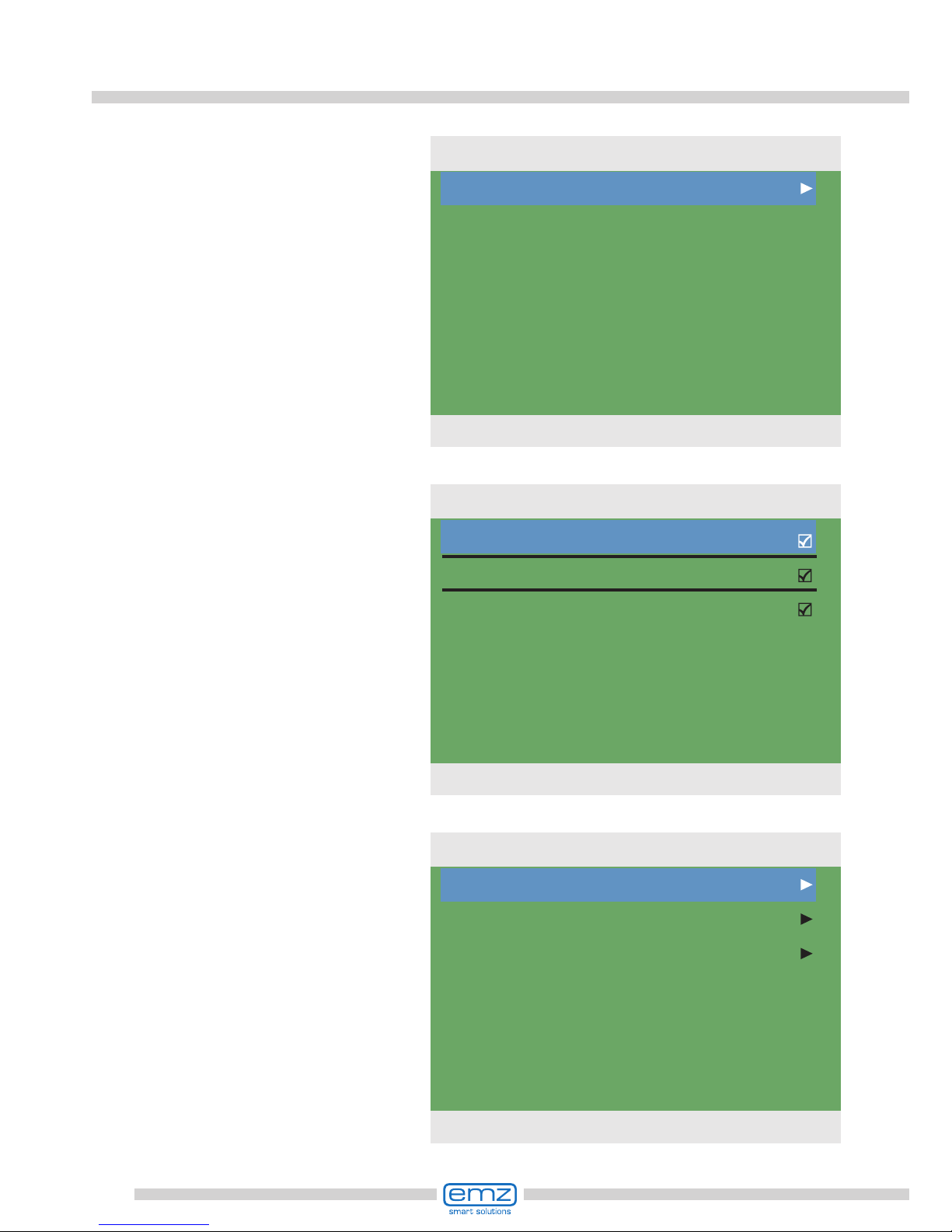
Active system
with current
temperatures
Display elements; example: communication screen
Activatable
menu item
Selection menu
Scroll arrow
Check box
Sub menu arrow
Date and time
Professional mode
Manual mode
Message
Number and name of menu
Date and time

13
Danger!
Mortal danger due to electrocution! Whenever work is performed on the
open terminal cover, all poles of the power supply must be
disconnected reliably and protected against being switched on again!
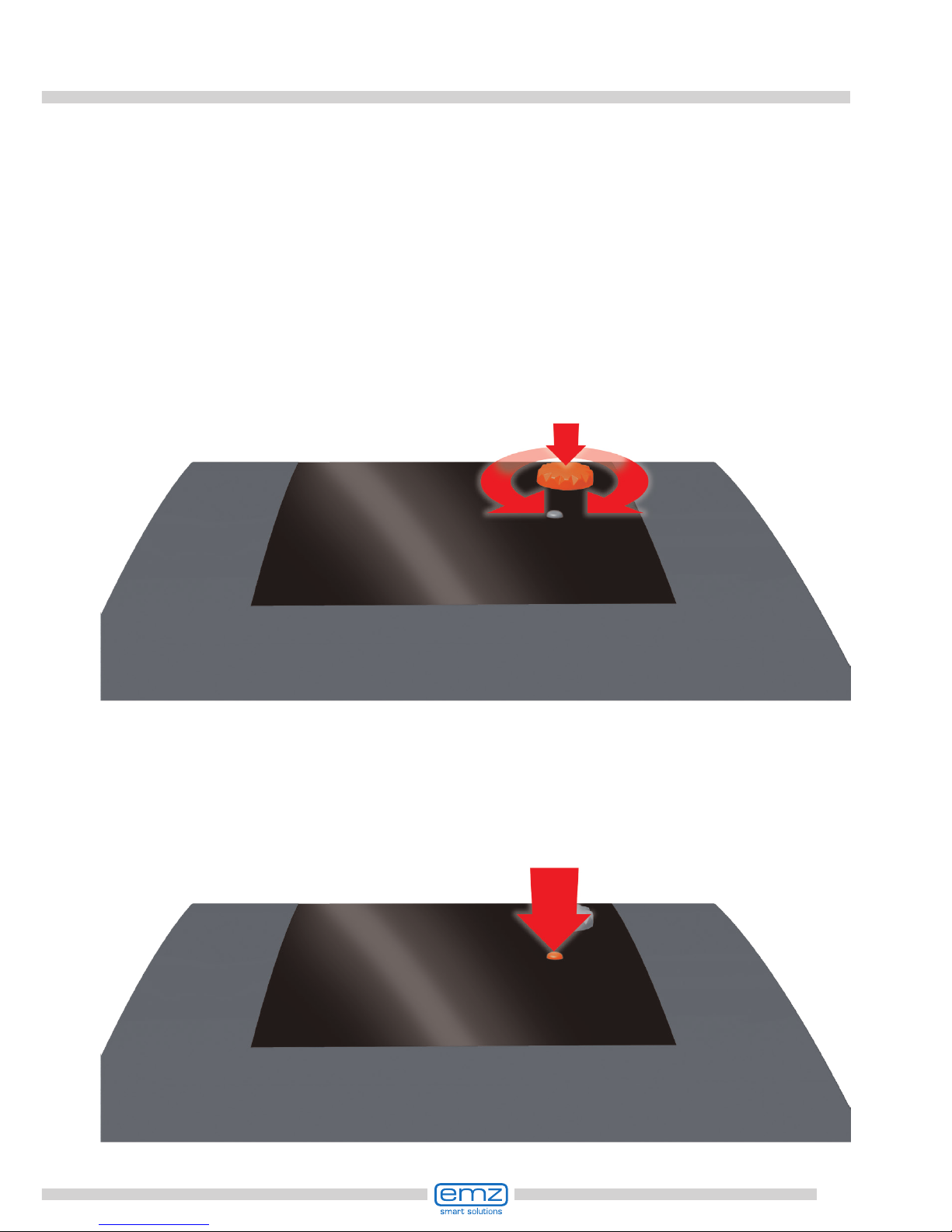
Opening the terminal cover
1 Release the lock screw.
2 Pull apart the sidewalls
of the terminal cover
at the lower third...
3 ...swivel the terminal
cover forward ...
4 ... push it upwards ...
5 ... and remove it.
Store the terminal cover
carefully and protect
it against damage!
To close the terminal cover,
reverse the opening procedure.

14
Wall-mounting
1 Fasten the top securing bolt so
that a space of 2 to 3 mm is
created between the wall and
the screw head.
2 Move the device so that the
upper fastening port is located
above the screw head ...
3 ... and push it downwards.
4 Fasten the lower securing bolt.
If necessary, use dowel
pins for wall-mounting!
Important!
The device corresponds to protection type IP 20 - make sure the
appropriate prerequisites exist on the envisaged place of installation.
Do not use the housing base as drill template.
A device with damaged housing must not be operated!

15
Connection to power supply
The differential temperature controller smart Sol plus is connected to the
power supply via three groups of spring-type terminals which are
visible once the terminal cover is opened.
To introduce the cables, release the screws on the strain relief device;
if necessary, remove the strain relief device.
In case of ush mounting of the cables, the break-out segments in the housing
base can be removed carefully and the cables routed through these ports.
The central terminal block is the interface to a potential-free change-over contact.
The spring-type terminals for the Power, RO1 to RO4 and REL, and for TS1 to TS10
can accommodate solid wires up to a cross section of 1.5 mm2.
Appropriate stranded wires must be preassembled with cable end sleeves.
For the strain relief device function, TS1 to TS10 and REL require
cable cross sections of at least 5mm, for Power, RO1 to RO4 at least 7mm.
Danger!
Mortal danger due to electrocution! Whenever work is performed
on the open terminal cover, all poles of the power supply must be
disconnected reliably and protected against being switched on again!
Terminal block
RO1-RO4/Power
Terminal
block REL
Terminal block
TS1-TS10

16
Connection to power supply
Connection of a pump to REL
Connection diagram for a pump to REL:
Connection of a switching valve to RO1-RO4
Connection diagram for a switching Connection diagram for a switching
valve without power supply to RO4: valve with power supply to RO4:
Connection of a switching valve to REL
Connection diagram for a switching Connection diagram for a switching
valve without power supply to REL: valve with power supply to REL:
Valve
L
N
PE
Valve
L‘
N
L
Valve
L
L‘
N
Valve
L‘
N
PE
Pump
L‘
N
PE

17
Connection to power supply
High-efciency pump:
A high-efciency pump can be connected via RO1 to RO4.
The appropriate control signal is issued at TS7 to TS10.
Thus, TS7 to TS10 is no longer available as input.
The control signal may be an analog voltage 0 - 10V or a PWM signal.
For further details, please refer to the pump specication.
For denition and settings, the professional mode under 1.2.9 has been provided.
RO1 to RO4:
230V supply of the
high-efciency pump
TS7-TS10: PWM-control signal
for the high-efciency pump
Left-hand terminal GND
Right-hand termin.: Signal
Volumetric ow sensor:
Measurement of solar radiation (heat quantity):
The solar yield is calculated from the ow rate and the differential temperature.
The differential temperature is the difference in the temperature of the collector
sensor and the solar circuit return line sensor. There are various technical options:
a) Use of a vortex volumetric ow sensor with 2 analog signals for ow rate and
temperature. The vortex sensor can be inserted directly at the plug connector provided
behind the TS terminals. All plant layouts (systems) permit solar radiation.
Pin assignment
b) Impeller sensor (incrementation input)
An impeller sensor can be connected to TS6 to TS8 and must be adjusted during
installation. The temperature sensor for the solar return line must be set
in the menu ›1.1.4 Heat quantities‹.
Solar yield measurement with impeller sensors is possible for all systems.

18
Connection to power supply
For connection, press the actuation pushbutton
of the spring-type terminal using a screwdriver and
insert the wire to its stop in the appropriate port.
Release the actuation pushbutton and
pull the cable slightly to ensure that it
is safely clamped.
Important!
Before closing the terminal cover, make
sure the strain relief device is tightened safely.
Check once more that all cables are in good
condition and connected correctly.
The strain relief device can only ensure solid
clamping if the cables are not stripped to a length
of over 35 mm.
Insulation of the individual wires must be
removed over a length of 9 - 10 mm to ensure
safe electric contact in the spring-type terminal.
Stranded wires must be provided with cable end sleeves!
9-10 mm
max.
35 mm

19
Data interfaces
The solar controller has the following data interfaces:
The cut-outs at the left of the housing base accommodate a
USB port as well as a slot for a storage medium (SD card).
These interfaces are used, for example, for reading of er-
ror messages or log data or loading of software updates.
The USB port provides access to the SD card.
Only SD cards approved by emz must be used.
The controller automatically detects the SD card.
Prior to removing the SD card
›Rem.SD card safely‹ must be
selected in ›1.2 Settings‹,
otherwise data loss may occur.

20
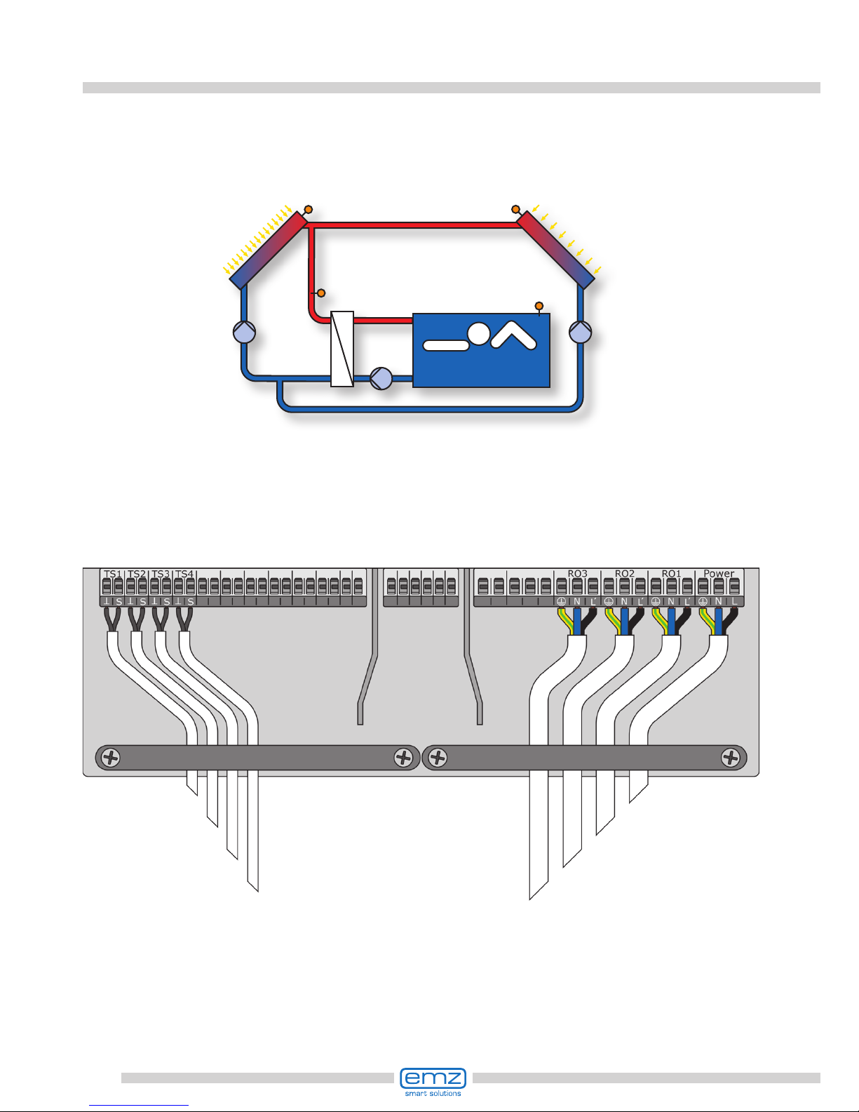
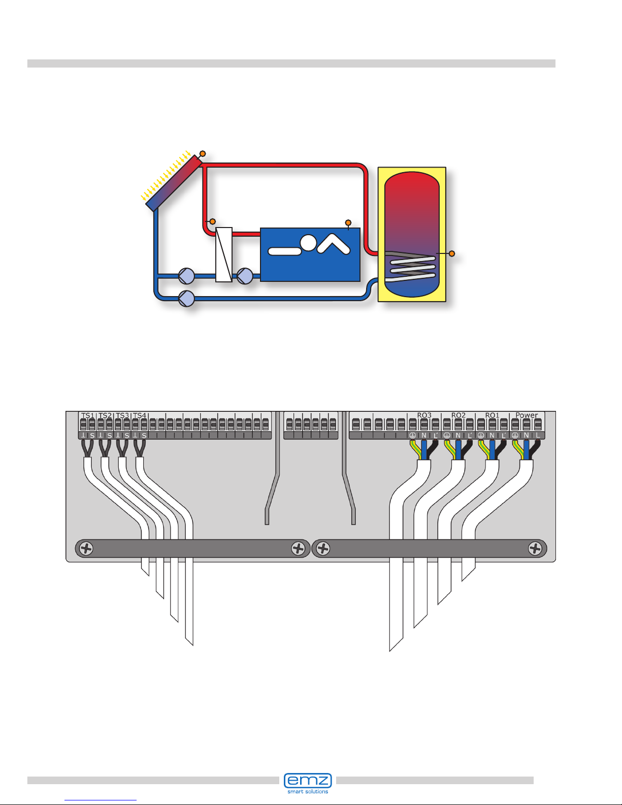
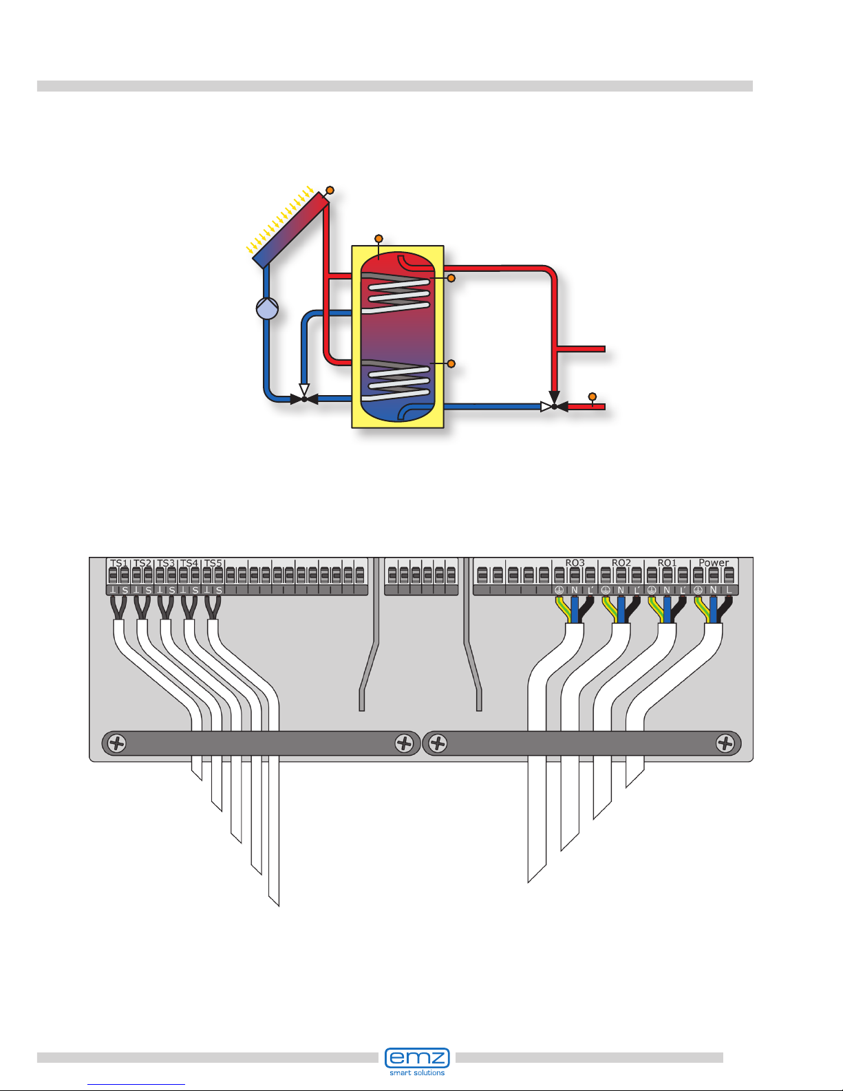
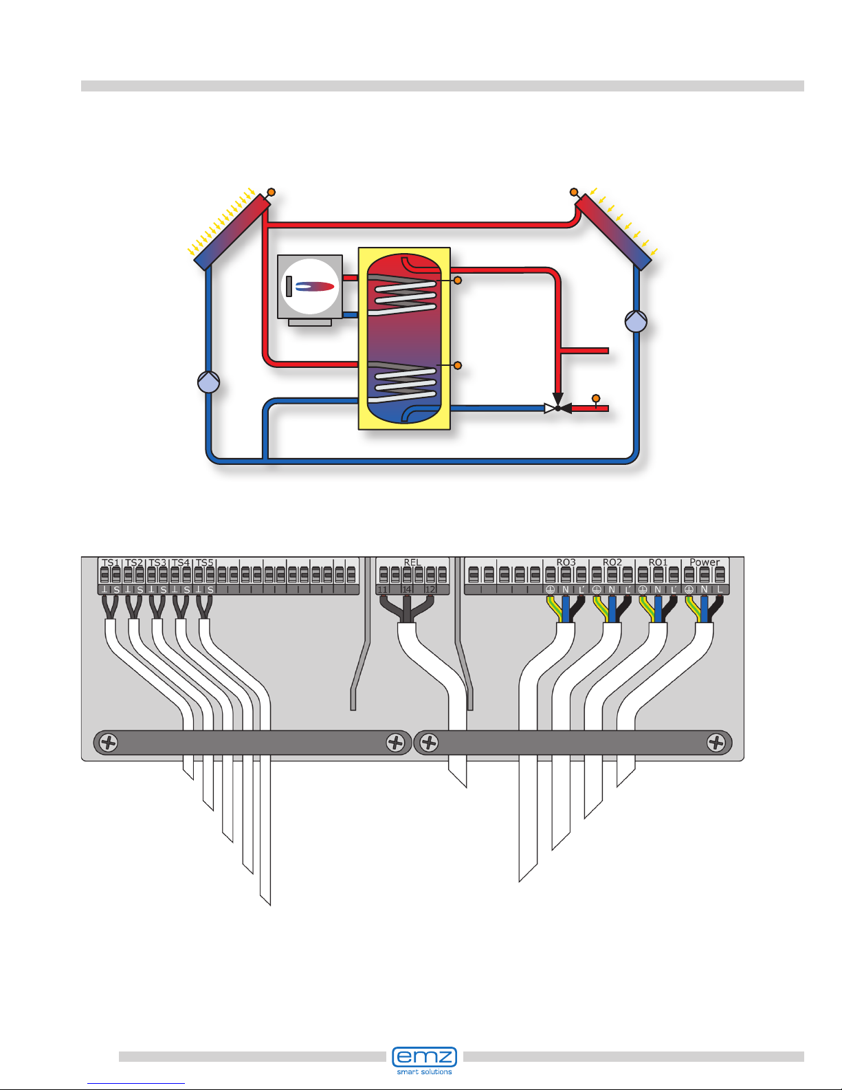
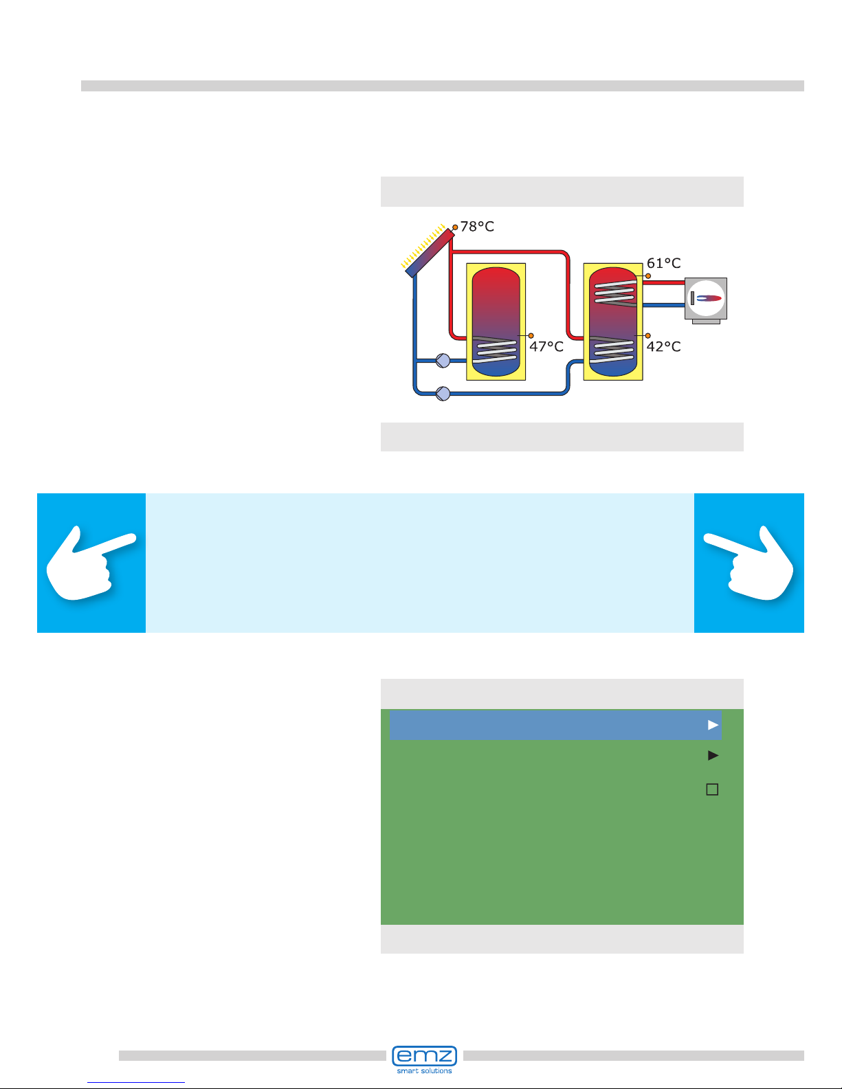
Hydraulic systems
Boiler with disable
recharge feature,
efciency optimization
Boiler with disable
recharge feature
time-/temperaturecontrolled, in combination
Boiler, e. g. using fossil
fuels/ solid fuels/
heat pump etc.
Hydraulic
heat exchanger
Temperature probe
Switching valve
Solar collector panel
Secondary yield
Solar collector panel
Main yield
Swimming pool
Warmwasserspeicher/
Pufferspeicher mit
Wärmetauschern
Warm water /
buffer tank without
heat exchanger
Heating pump
Return line
Supply line
Note!
Dene structure and design of the plant already when planning
the entire solar thermal system and align the design with the
one of the hydraulic systems of the controller!
If you want to complete an existing system or replace
the existing controller, please make sure that
smart Sol plus is compatible with the existing conguration!
The sensors are connected to TS1 to TS10, the order not being
signicant; pumps and valves are connected to RO1 to RO4 / REL - The
interfaces are assigned to the functions in question on commissioning.

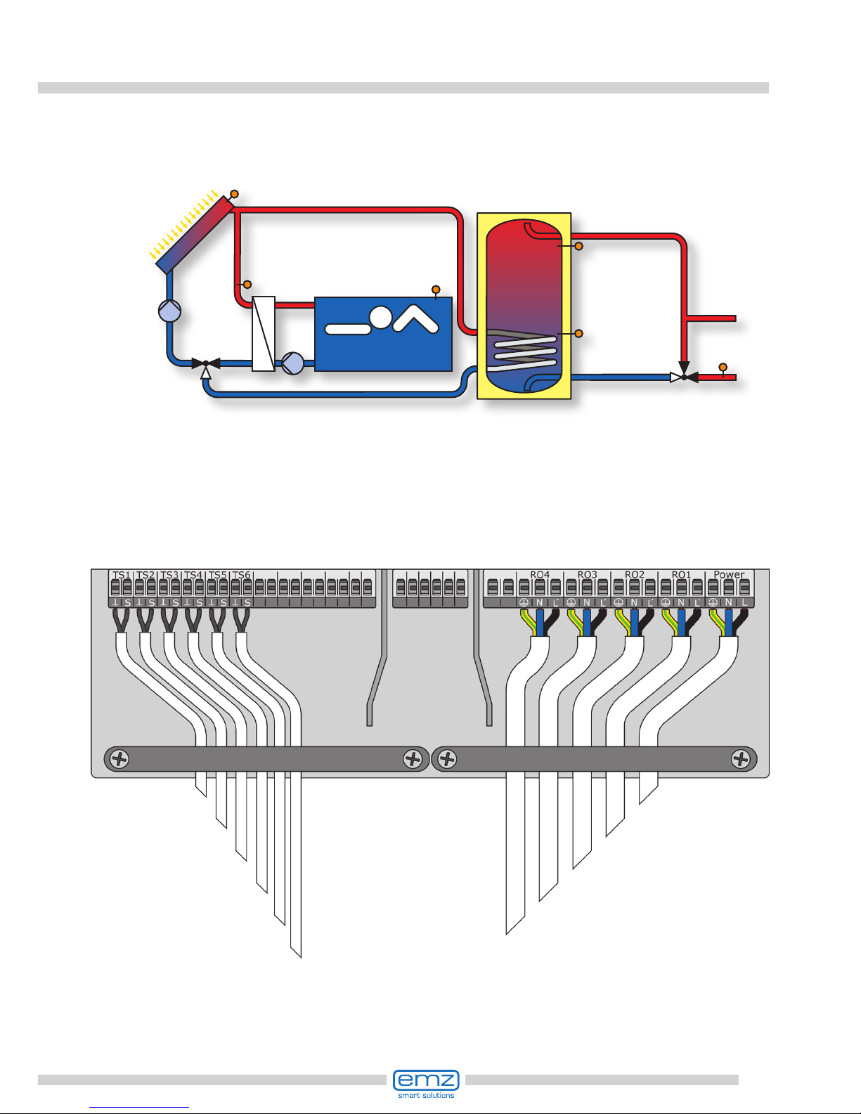
21
Hydraulic system 1
Collector
sensor 1
Connection to
power supply
Tank sensor 1,
bottom
Solar circuit pump 1
RO1
TS1
TS2
Tank 1
T1
Collector
sensor 1
Solar
circuit
pump 1
Tank
sensor 1,
bottom

22
Hydraulic system 2
Collector
sensor 1
Connection to
power supply
Tank sensor 1,
bottom
Solar circuit pump 1
Tank sensor 1, top
RO1
TS1
TS2
TS3
Tank 1
T1
Collector
sensor 1
Solar
circuit
pump 1
Tank
sensor 1,
bottom
Tank sensor 1,
top
Heating boiler
connection
according to
page 51-53
23
Hydraulic system 3
Collector
sensor 1
Connection to
power supply
Tank sensor 1,
bottom
Solar circuit pump 1
Tank sensor 1, top Charging area valve
TS3
TS2
TS1
RO2
RO1
Tank 1
T1
Collector sensor 1
Solar
circuit
pump 1
Tank
sensor 1,
bottom
Tank sensor 1,
top
Charging area valve

24
Hydraulic system 4
Collector
sensor 1
Connection to
power supply
Tank sensor 1,
bottom
Solar circuit pump 1
Tank sensor 1, top Charging area valve
TS3
TS2
TS1
RO2
RO1
Tank 1
T1
Collector
sensor 1
Solar
circuit
pump 1
Tank
sensor 1,
bottom
Tank sensor 1,
top
Charging
area
valve

25
Hydraulic system 5
Collector
sensor 1
Connection to
power supply
Tank sensor 1,
bottom
Solar circuit pump 1
Heat exchanger sensor Heat exchanger pump
RO2
TS1
RO1
TS2
TS3
Tank 1
T1
Collector
sensor 1
Solar
circuit
pump 1
Tank
sensor 1,
bottom
Heat ex-
changer
sensor
Heat
exchanger
pump
26
Hydraulic system 6
Collector
sensor 1
Connection to
power supply
Tank sensor 1,
bottom
Solar circuit pump 1
Tank sensor 1, top Heat exchanger pump
Heat exchanger sensor
RO2
TS1
RO1
TS2
TS4
Tank 1
T1
Collector
sensor 1
Solar
circuit
pump 1
Tank
sensor 1,
bottom
Heat ex-
changer
sensor
Heat
exchanger
pump
TS3
Tank sensor 1,
top
Heating boiler
connection
according to
page 51-53

27
Hydraulic system 7
Collector
sensor 1
Connection to
power supply
Tank sensor 1,
bottom
Solar circuit pump 1
Bypass sensor Bypass valve
RO1
TS1
TS3
RO2
TS2
Tank 1
T1
Collector
sensor 1
Solar
circuit
pump 1
Tank
sensor 1,
bottom
Bypass valve
Bypass
sensor

28
Hydraulic system 8
Collector
sensor 1
Connection to
power supply
Tank sensor 1,
bottom
Solar circuit pump 1
Tank sensor 1, top Bypass valve
Bypass sensor
RO1
TS1
TS4
RO2
TS2
Tank 1
T1
Collector
sensor 1
Solar
circuit
pump 1
Tank
sensor 1,
bottom
Bypass valve
Bypass
sensor
TS3
Tank sensor 1,
top
Heating boiler
connection
according to
page 51-53
29
Hydraulic system 9
Collector
sensor 1
Connection to
power supply
Tank sensor 1,
bottom
Solar circuit pump 1
Tank sensor 1, top Transfer pump
Tank sensor 2, bottom
TS4
RO1
TS1
TS3
TS2
RO2
Tank 1
T1
Tank 2
T2
Collector
sensor 1
Solar
circuit
pump 1
Tank
sensor 1,
bottom
Transfer
pump
Tank sensor 1,
top
Tank
sensor 2,
bottom
30
Hydraulic system 10
Note: Priority charging has
been set to T2 in the factory.
Collector
sensor 1
Connection to
power supply
Tank sensor 1,
bottom
Solar circuit pump 1
Tank sensor 2, bottom Solar circuit pump 2
TS2
TS1
TS3
RO1
RO2
Tank 1
T1
Tank 2
T2
Collector
sensor 1
Solar circuit
pump 1
Tank
sensor 1,
bottom
Solar circuit pump 2
Tank
sensor 2,
bottom
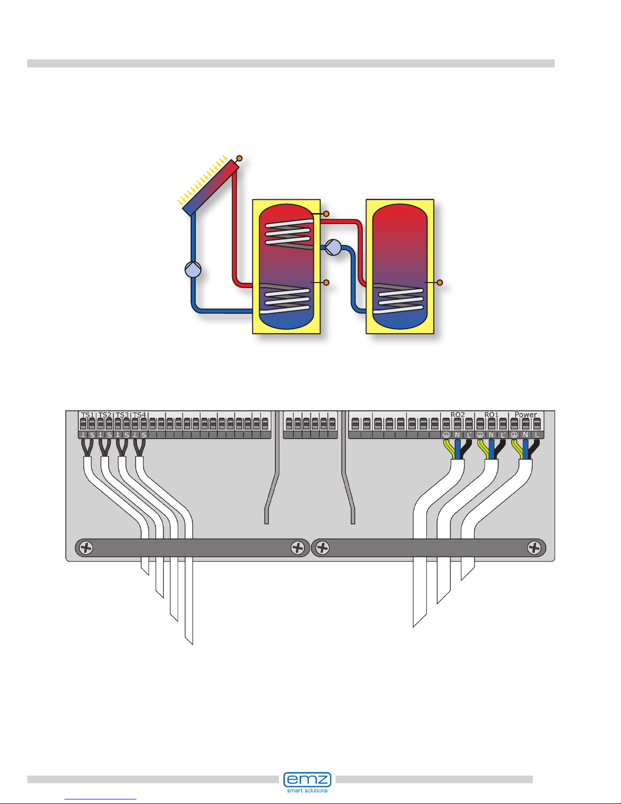
31
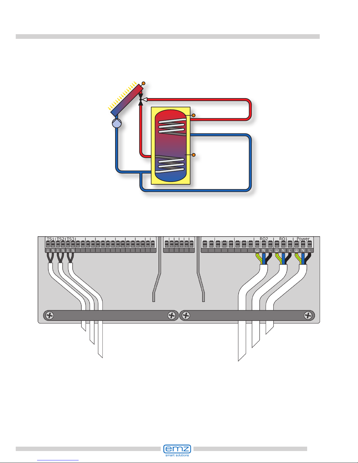
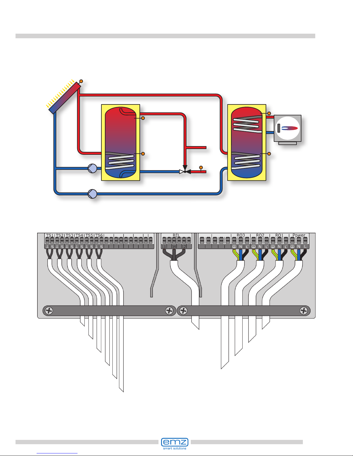
Hydraulic system 11
Note: Priority charging has
been set to T2 in the factory.
Collector
sensor 1
Connection to
power supply
Tank sensor 1,
bottom
Solar circuit pump 1
Tank sensor 1, top Solar circuit pump 2
Tank sensor 2, bottom
TS2
TS1
TS4
RO1
RO2
Tank 1
T1
Tank 2
T2
Collector
sensor 1
Solar circuit
pump 1
Tank
sensor 1,
bottom
Solar circuit
pump 2
Tank
sensor 2,
bottom
TS3
Tank sensor 2,
top
Heating boiler
connection
according to
page 51-53

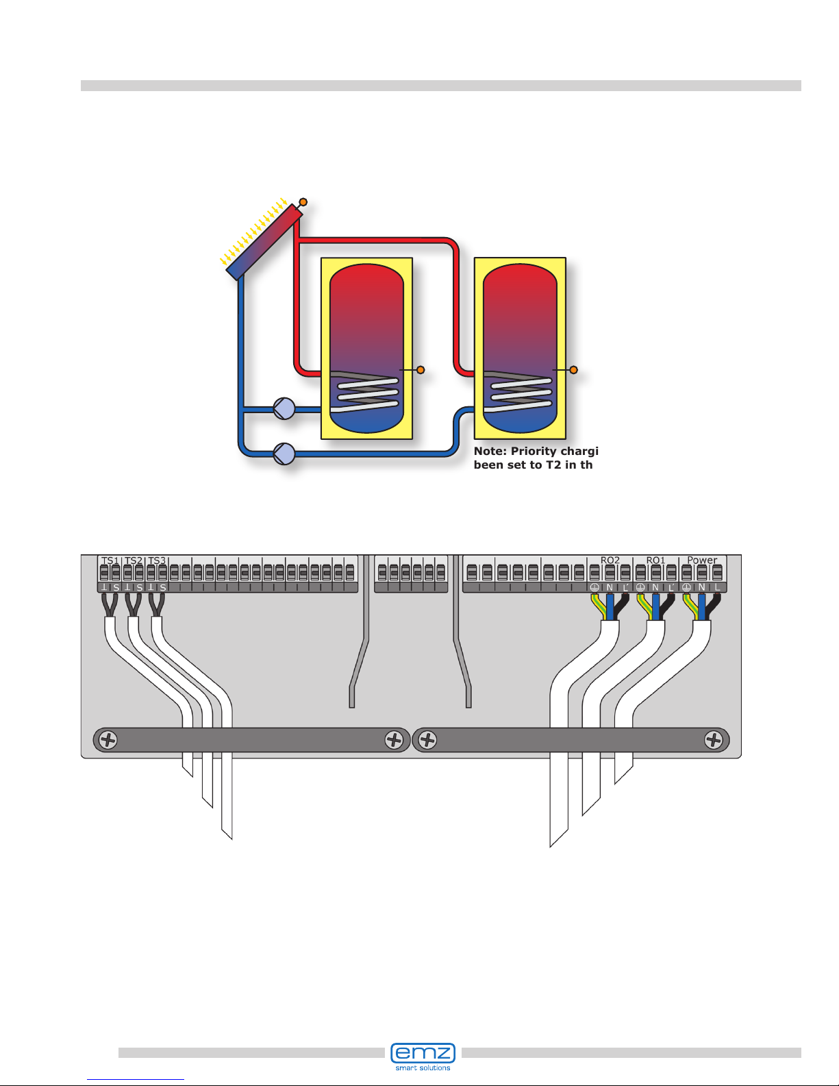
32
Hydraulic system 12
Note: Priority charging has
been set to T2 in the factory.
Collector
sensor 1
Connection to
power supply
Tank sensor 1,
bottom
Solar circuit pump 1
Tank sensor 2, bottom Tank switching valve
TS2
RO1
TS1
RO2
TS3
Tank 1
T1
Tank 2
T2
Collector
sensor 1
Solar circuit
pump 1
Tank
sensor 1,
bottom
Tank switching valve
Tank
sensor 2,
bottom

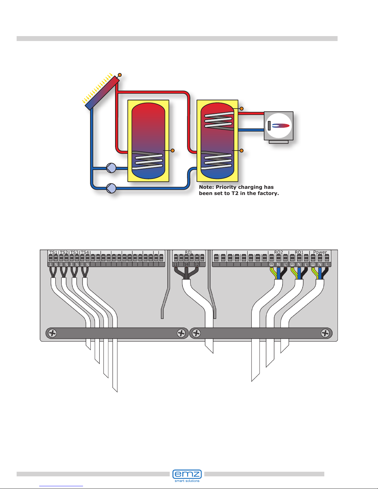
33
Hydraulic system 13
Note: Priority charging has
been set to T2 in the factory.
Collector
sensor 1
Connection to
power supply
Tank sensor 1,
bottom
Solar circuit pump 1
Tank sensor 2, top Tank switching valve
Tank sensor 2, bottom
TS2
RO1
TS1
RO2
TS4
Tank 1
T1
Tank 2
T2
Collector
sensor 1
Solar circuit
pump 1
Tank
sensor 1,
bottom
Tank switching valve
Tank
sensor 2,
bottom
TS3
Tank sensor 2,
top
Heating boiler
connection
according to
page 51-53

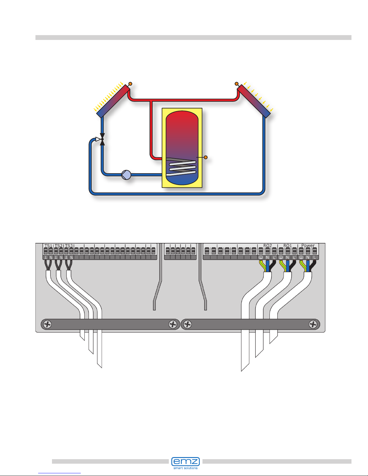
34
Hydraulic system 14
Collector
sensor 1
Connection to
power supply
Tank sensor 1,
bottom
Solar circuit pump 1
Collector sensor 2 Solar circuit pump 2
TS2
TS1
TS3
RO1
Tank 1
T1
Collector
sensor 1
Solar circuit
pump 1
Tank
sensor 1,
bottom
Collector
sensor 2
RO2
Solar circuit
pump 2

35
Hydraulic system 15
Collector
sensor 1
Connection to
power supply
Tank sensor 1,
bottom
Solar circuit pump 1
Tank sensor 1, top Solar circuit pump 2
Collector sensor 2
TS3
TS2
TS1
TS4
RO1
Tank 1
T1
Collector
sensor 1
Solar circuit
pump 1
Tank
sensor 1,
bottom
Collector
sensor 2
RO2
Solar circuit
pump 2
Tank sensor 1,
top
Heating boiler
connection
according to
page 51-53
36
Hydraulic system 16
Collector
sensor 1
Connection to
power supply
Tank sensor 1,
bottom
Solar circuit pump 1
Collector sensor 2 Three-way valve
TS2
TS1
TS3
RO1
Tank 1
T1
Collector
sensor 1
Solar circuit
pump 1
Tank
sensor 1,
bottom
Collector
sensor 2
RO2
Three-way valve

37
Hydraulic system 17
Collector
sensor 1
Connection to
power supply
Tank sensor 1,
bottom
Solar circuit pump 1
Tank sensor 1, top Three-way valve
Collector sensor 2
TS3
TS2
TS1
TS4
RO1
Tank 1
T1
Collector
sensor 1
Solar circuit
pump 1
Tank
sensor 1,
bottom
Collector
sensor 2
RO2
Tank sensor 1,
top
Three-way valve
Heating boiler
connection
according to
page 51-53

38
Hydraulic system 18
Collector
sensor 1
Connection to
power supply
Tank sensor 1,
bottom
Solar circuit pump 1
Tank sensor 2, bottom Tank switching valve
TS2
RO1
TS1
RO2
TS3
Tank 1
T1
Tank 2
T2
Collector sensor 1
Solar circuit
pump 1
Tank
sensor 1,
bottom
Tank switching valve
Tank
sensor 2,
bottom
Note: Priority charging has
been set to T2 in the factory.

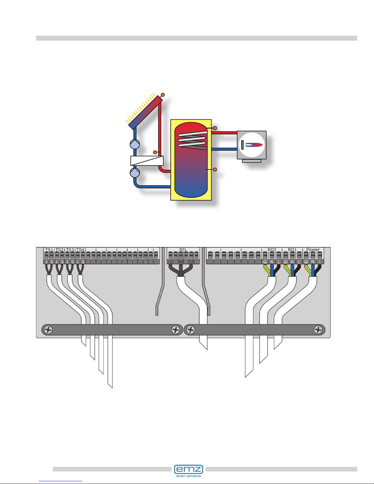
39
RO1
Solar
circuit
pump 1
RO2
Three-way valve
Tank 1
T1
Tank 2
T2
Tank 3
T3
TS1
Collector sensor 1
TS2
Tank
sensor 1,
bottom
TS3
Tank
sensor 2,
bottom
TS4
Tank
sensor 3,
bottom
RO3
Three-way valve
Hydraulic system 19
Collector
sensor 1
Connection to
power supply
Tank sensor 1,
bottom
Solar circuit pump 1
Tank sensor 2, bottom Three-way valve
Tank sensor 3, bottom Three-way valve

40
Hydraulic system 20
Collector
sensor 1
Connection to
power supply
Tank sensor 1,
bottom
Solar circuit pump 1
Tank sensor 1, top
Return line sensor
TS3
TS2
TS1
RO1
Tank 1
T1
Collector
sensor 1
Solar circuit
pump 1
Tank
sensor 1,
bottom
Tank
sensor
1, top
TS4
Return line
sensor
Three-way valve,
return temperature
increase
RO3
Three-way valve,
return temperature increase

41
Hydraulic system 21
Collector
sensor 1
Connection to
power supply
Heat exchanger
sensor
Solar circuit pump 1
Swimming pool sensor Heat exchanger pump
Collector sensor 2 Three-way valve
TS3
TS2
TS1
RO1
1 Collector sensor 2
Solar circuit
pump 1
TS4
Swimming
pool sensor
Heat
exchanger
sensor
Heat exchanger pump
RO3
RO2
Three-way valve
42
Hydraulic system 22
Collector
sensor 1
Connection to
power supply
Heat exchanger
sensor
Solar circuit pump 1
Swimming pool sensor Solar circuit pump 2
Collector sensor 2 Heat exchanger pump
TS3
TS2
TS1
RO1
1 Collector sensor 2
Solar circuit
pump 1
TS4
Swimming
pool sensor
Heat
exchanger
sensor
Heat exchanger pump
RO3
RO2
Solar circuit
pump 2
43
Hydraulic system 23
Collector
sensor 1
Connection to
power supply
Heat exchanger
sensor
Solar circuit pump 1
Swimming pool sensor Solar circuit pump 2
Tank sensor 1, bottom Heat exchanger pump
TS3
TS2
TS1
RO1
Collector sensor 1
Solar circuit
pump 1
Tank
sensor 1,
bottom
TS4
Swimming
pool sensor
Heat
exchanger
sensor
Heat exchanger pump
RO3
Tank 1
T1
RO2
Solar circuit pump 2
Note: Priority charging has
been set to T1 in the factory.

44
Hydraulic system 24
Collector
sensor 1
Connection to
power supply
Heat exchanger
sensor
Solar circuit pump 1
Swimming pool sensor Heat exchanger pump
Tank sensor 1, bottom Three-way valve, buffer tank 1
TS3
TS2
TS1
RO1
Collector sensor 1
Solar circuit
pump 1
Tank
sensor 1,
bottom
TS4
RO3
Swimming
pool sensor
Heat
exchanger
sensor
Heat exchanger pump
Three-way valve,
buffer tank 1
RO2
Tank 1
T1
Note: Priority charging has
been set to T1 in the factory.
45
Hydraulic system 25
Collector
sensor 1
Connection to
power supply
Tank sensor 1,
bottom
Solar circuit pump 1
Tank sensor 1, top Charging area valve
Tank sensor return line Three-way valve,
return temperature increase
Return line sensor
TS3
TS1
RO1
Tank 1
T1
Collector sensor 1
Solar
circuit
pump 1
Tank sensor 1,
top
TS2
Tank sensor 1,
bottom
Return
line sensor
Three-way valve, return
temperature increase
RO3
RO2
Charging area valve
TS5
Tank sensor
return line
TS4
46
Hydraulic system 26
Collector
sensor 1
Connection to
power supply
Tank sensor 1,
bottom
Solar circuit pump 1
Tank sensor 1, top Solar circuit pump 2
Collector sensor 2 Three-way valve,
return temperature increase
Return line sensor
TS3
TS1
TS4
RO1
Tank 1
T1
Collector
sensor 1
Solar circuit
pump 1
Collector
sensor 2
Tank sensor 1,
top
RO2
Solar circuit
pump 2
TS2
Tank sensor 1,
bottom
TS5
Return
line sensor
Three-way valve, return
temperature increase
RO3
Heating boiler
connection
according to
page 51-53
47
Hydraulic system 27
Collector
sensor 1
Connection to
power supply
Heat exchanger
sensor
Solar circuit pump 1
Swimming pool sensor Heat exchanger pump
Tank sensor 1, bottom Three-way valve, buffer tank 1
Tank sensor 1, top Three-way valve,
return temperature increase
Return line sensor
TS5
Tank sensor 1,
top
TS4
Tank sensor 1,
bottom
Return line
sensor
Three-way valve, return
temperature increase
RO4
TS6
TS3
TS2
TS1
RO1
Collector sensor 1
Solar circuit
pump 1
RO3
Swimming
pool sensor
Heat
exchanger
sensor
Heat exchanger pump
Three-way valve,
buffer tank 1
RO2
Tank 1
T1
Note: Priority charging has
been set to T1 in the factory.

48
Hydraulic system 28
Collector
sensor 1
Connection to
power supply
Tank sensor 1,
bottom
Solar circuit pump 1
Tank sensor 1, top Three-way valve
Collector sensor 2 Three-way valve,
return temperature increase
Return line sensor
TS3
TS1
TS4
RO1
Tank 1
T1
Collector
sensor 1
Solar circuit
pump 1
Collector
sensor 2
Tank sensor 1,
top
RO2
TS2
Tank sensor 1,
bottom
TS5
Return
line sensor
Three-way valve, return
temperature increase
RO3
Three-way valve
Heating boiler
connection
according to
page 51-53
49
Hydraulic system 29
Collector
sensor 1
Connection to
power supply
Tank sensor 1,
bottom
Solar circuit pump 1
Tank sensor 1, top Solar circuit pump 2
Tank sensor 2, bottom Three-way valve,
return temperature increase
Tank sensor 2, top
Return line sensor
TS3
TS1
RO1
Tank 1
T1
Collector
sensor 1
Solar
circuit
pump 1
Tank sensor 1,
top
TS2
Tank sensor 1,
bottom
TS6
Return line
sensor
Three-way valve, return
temperature increase
RO3
RO2
Solar
circuit
pump 2
Tank 2
T2
TS5
Tank sensor 2,
top
TS4
Tank sensor 2,
bottom
Note: Priority charging has
been set to T2 in the factory.
Heating boiler
connection
according to
page 51-53

50
Hydraulic system 30
Collector
sensor 1
Connection to
power supply
Tank sensor 1,
bottom
Solar circuit pump 1
Tank sensor 1, top Tank switching valve
Tank sensor 2, bottom Three-way valve,
return temperature increase
Tank sensor 2, top
Return line sensor
TS3
TS1
RO1
Tank 1
T1
Collector
sensor 1
Solar circuit
pump 1
Tank sensor 1,
top
TS2
Tank sensor 1,
bottom
TS6
Return
line sensor
Three-way valve, return
temperature increase
RO3
RO2
Tank switching
valve
Tank 2
T2
TS5
Tank sensor 2,
top
TS4
Tank sensor 2,
bottom
Note: Priority charging has
been set to T2 in the factory.
Heating boiler
connection
according to
page 51-53
51
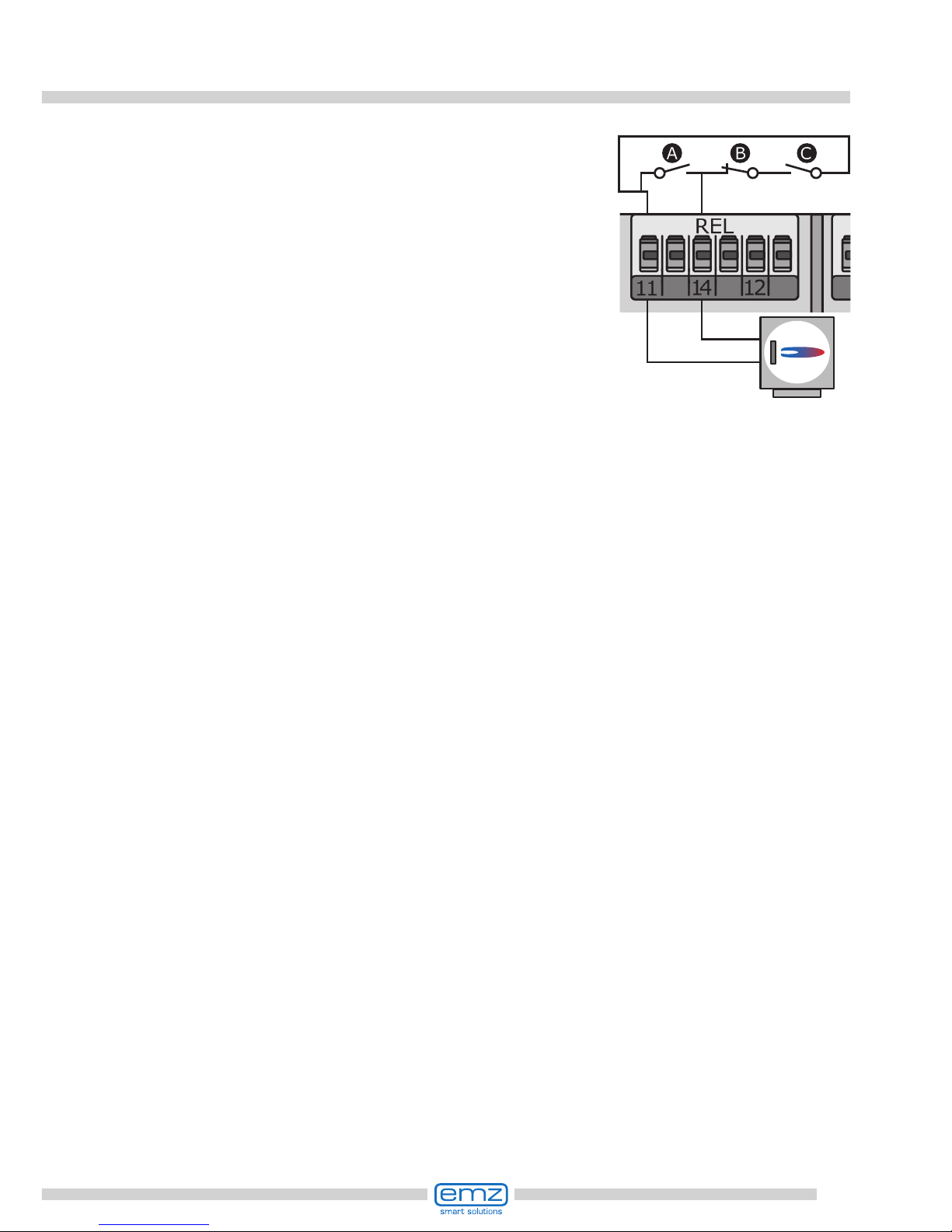
Functions for boiler control
The functions for boiler control are accomplished
via the potential-free relay contact which is connected
accordingly to the relevant interface of the heating boiler.
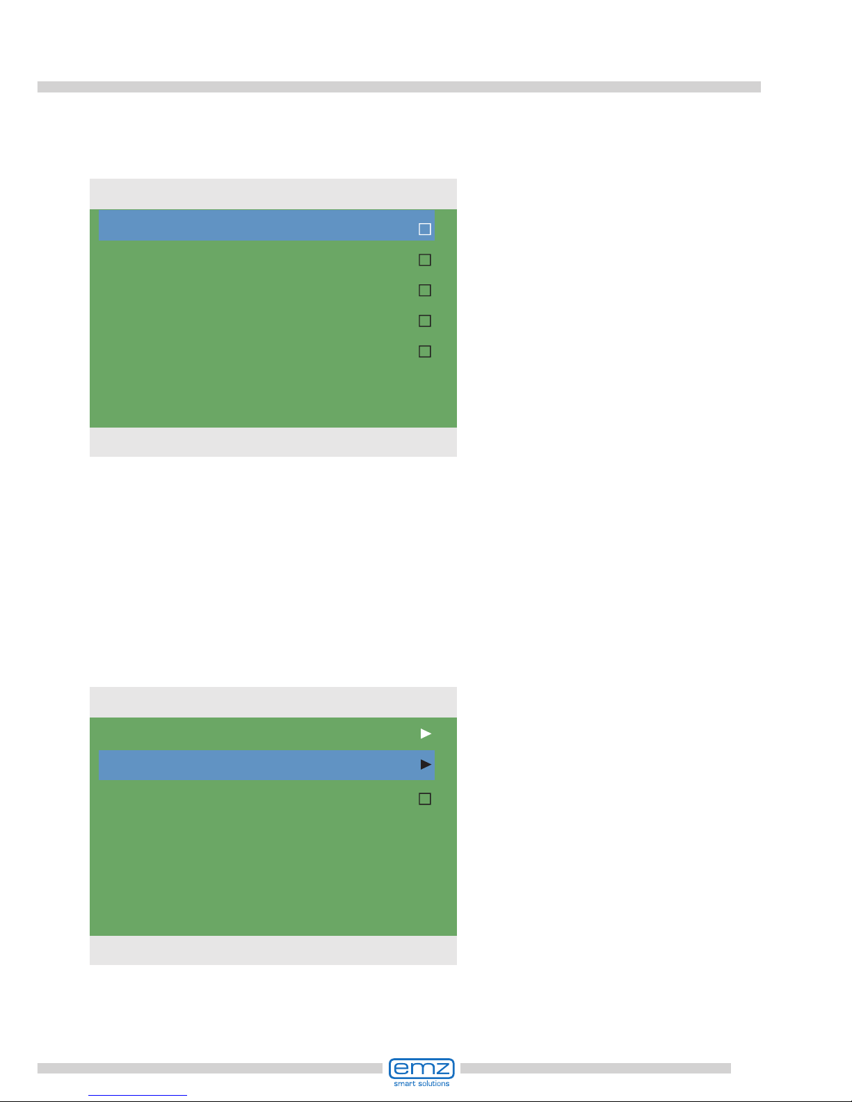
The individual functions are assigned
the following priorities:
A Anti-legionella priority 1
B recharge suppression priority 2
C reheating priority 3
Boiler
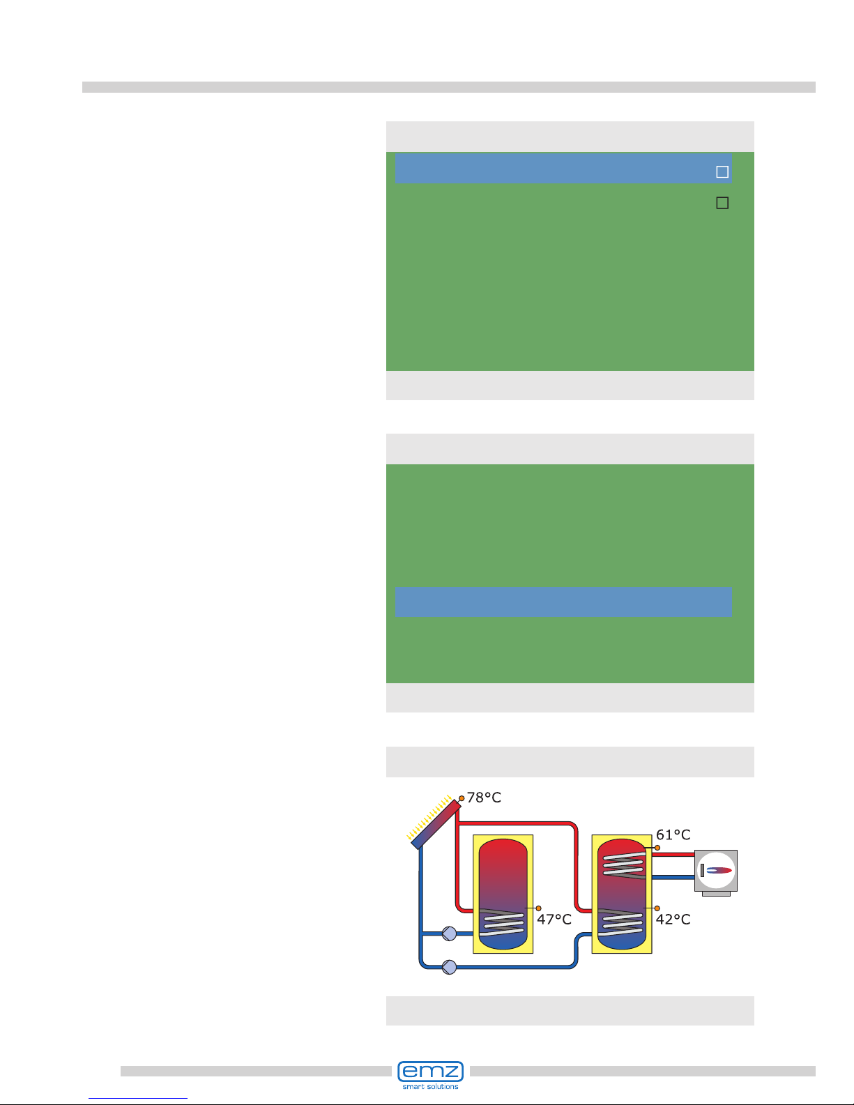
Anti-legionella function
The anti-legionella functions checks if the minimum heating for reduction of legionella
has been achieved in the tank due to heating activity or solar heat within a set interval.
f no sufcient heating has been achieved by these means the controller starts a reheat
cycle, specically for reduction of legionella.
The tter must set the parameters based on the applicable general directives and local
requirements. The time of the disinfection cycle can be determined freely.
Reheat function
The temperature sensor in the upper tank area supplies the values for reheating.
For oil or gas operated systems, reheating takes place via the heating boiler.
For solid-fuel boilers, reheating takes place via the heat present in the drinking water
tank. To this effect, the temperature within the tank must be within preset limits.
The temperature control is interlinked with six time blocks.
Reheating is activated as soon as the temperature falls below
the set value by the hysteresis value in the current time block.
When the set value is exceeded the reheating cycle stops.
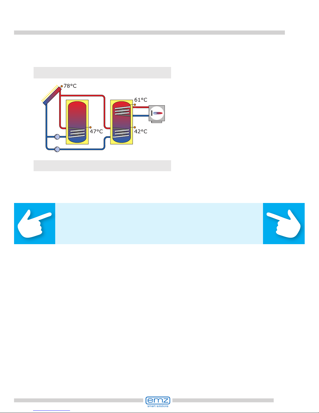
Disable recharge
The efciency of a solar plant increases as the recharge of the tank from the
boiler decreases. Consequently, „disable recharge“ means that
recharging of the water tank is blocked by the boiler.
Time-controlled disable recharge
Recharge is blocked by the boiler for specic phases via a time program.
Within the preset period of time (for ex. 7 to 19 h), recharge is blocked completely
by the boiler without requiring the minimum temperature to this effect.

52
Functions for boiler control
Time-/temperature-controlled disable recharge
If a minimum temperature in the tank is exceeded, disable recharge is activated.
This function can be activated in parallel to the time program.
If the preset minimum temperature (e. g. 45°C) in the tank
is exceeded, recharge of the tank is disabled by the boiler.
If, however, the minimum temperature is no longer reached, recharge is enabled
by the boiler no matter whether the time program blocks recharge or not.
Efciency-optimized recharge suppression
If the calculated minimum temperature in the buffer tank is exceeded, the
disabled recharge feature is activated. The installer can specify two weighting
factors in menu 1.4.3 for the calculation of this minimum temperature:
Factor 1 Parameter values from 1-10 whereby:
Solar yield 1 = more solar yield, less recharge by the boiler
:
10 = less solar yield, more recharge by the boiler
Factor 2 Parameter values from 1-10 whereby:
Comfort 1 = lower comfort, less recharge by the boiler
:
10 = higher comfort, more recharge by the boiler
t
T
Factor 1 = 7
Factor 2 = 7
t
T
Factor 2 = 1
Factor 1 = 5
t
T
Factor 2 = 5
Factor 1 = 1
A exible minimum
temperature is thus
calculated once per
day which disables the
recharge by the boiler.
This exible minimum
temperature is between
›T min. tank‹ and ›T target‹.
Q
t
Solar energy history
t
T
T min. tank (e.g.35°C)
T targ. (e.g. 45°C)
Recharge active
Recharge suppressed
53
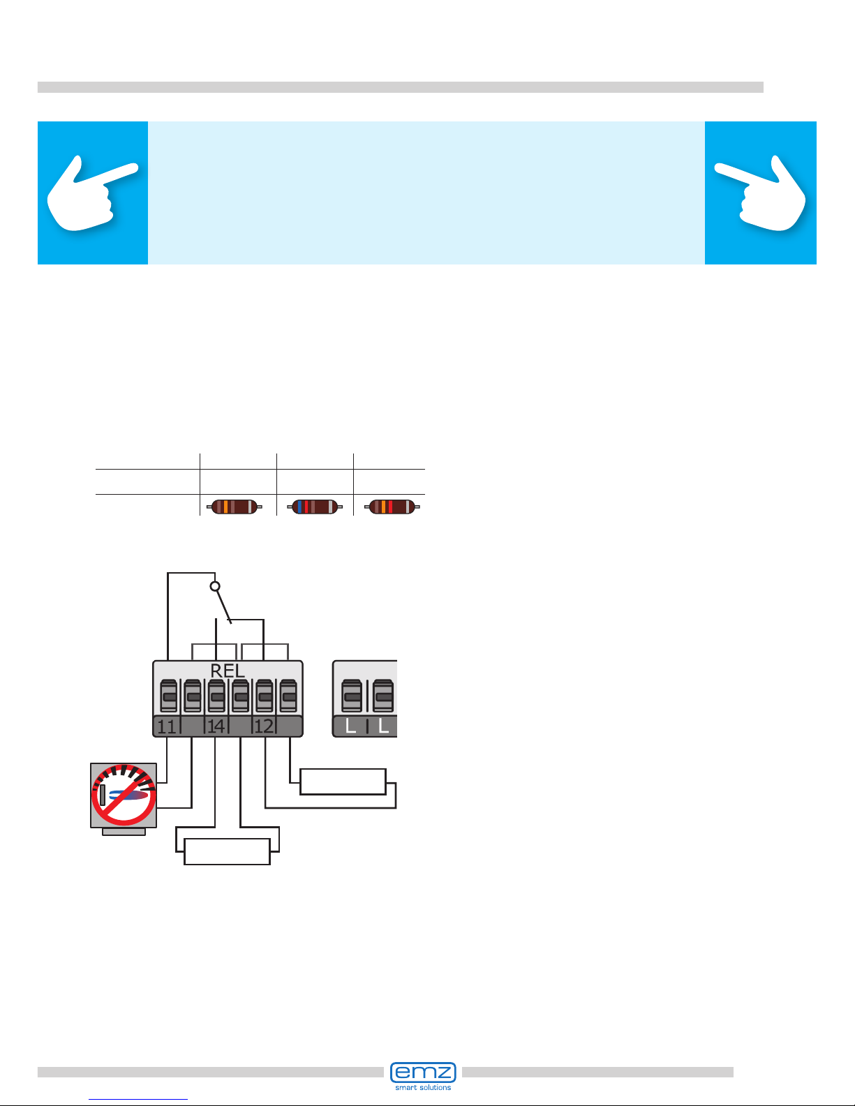
Functions for boiler control
Sensor type Pt 100 Pt 500 Pt 1000
R Terminal 12 130 Ω 620 Ω 1,3 kΩ
Colour code
Boiler
R (T=70°C)
Tank sensor
top
Note!
For boilers without control input, the functions for boiler control
can be accessed by the simulation of temperature values.
To enable reheating or anti-legionella functions, the corresponding
boiler temperature must be increased at the boiler control.
The differential temperature controller smart Sol plus
regulates the boiler control functions by a xed value
resistance simulating a charged buffer tank for the boiler.
The resistance value depends on the type of sensor the heating
is adjusted to - this information is provided in the boiler manual.
Connection provided at the
REL terminal block, as illustrated.

54
T OFF
ROx
T
t
T ON
Temperature thermostat ›Cooling‹:
T ON > T OFF The output is activated once the
›T ON‹ temperature is reached, and deactivated
once the ›T off‹ temperature is reached.
T ON
ROx
T
t
T OFF
Temperature thermostat ›Heating‹:
T OFF > T ON The output is deactivated once the
›T OFF‹ temperature is reached, and activated
once the ›T ON‹ temperature is reached.
Thermostat functions
ROx
8:00 9:00
t
T OFF
ROx
T
t
T ON
8:00 9:00
The controller’s free outputs can be used as thermostats for various applications.
Settings must be made to this effect in professional mode under ›1.3.1 Thermostat‹.
Control signals can be dened as temperature thermostat, timer,
timer thermostat or temperature comparator.
Timer-Thermostat
Combination of timer and thermostat.
Once at least one of these criteria is met,
the output is activated.
Temperature comparator
Any temperature difference to a reference
sensor will trigger a control signal:
The output is activated once ›dT ON‹ is reached,
and deactivated once ›dT OFF‹ is reached.
Timer function:
The output is activated
within a selected time frame.
dT OFF
dT ON
ROx
TSx
T
t
Reference sensor

55
RO1
TS1
TS2
TS3
Speicher 1
SP1
Soft water station AQA solar
In the main menu, information transmitted by the soft water station can
be retrieved under ›1.8 AQA solar‹.
In a specic equipment version (with an extension module), the differential
temperature controller smart Sol plus can be connected to the soft water station
AQA solar of BWT Wassertechnik GmbH, Schriesheim.
AQA solar is a decalcication plant based on an ion exchanger, which ensures that
the water lines and heat exchangers in your home are not damaged by scaling.
In case of very intense temporary heating of the drinking water, especially with
thermal solar systems, decalcication is very useful to maintain efciency.
Setup and operation of the equipment combination smart Sol plus and AQA solar
is described in separate documentation and/or the operating manual of BWT.
Integration of the soft water station
is possible in all hydraulic systems of
the smart Sol plus, and is displayed,
e. g.:
For connection, the terminals
›Tx‹, ›Rx‹ and ›Gnd‹ above
the interface terminals TS1 to TS10
are provided on the extension modules.
Soft water
Flow rate
Soft water delivery
recent regeneration
Salt consumption
421l/h
317m3
24.08.2012 09:00
66g
1.8 AQA solar
25.08.2012 10:30

56

57
Commissioning mode
›0.1 Language‹ appears after
a short booting sequence.
Various languages are available in
this version of the smart Sol plus.
Activate the required version and
acknowledge by pressing ›Next‹.
This is an explanation in terms of an example of commissioning of the
differential temperature controller smart Sol plus; details vary along
with the hydraulic conguration and the software version.
Commissioning is communicated in plain text; the user must make a
selection, acknowledge and - if applicable - jump to the next menu item.
The differential temperature controller smart Sol plus accompanies you during the
entire conguration and interrogates everything it must know for optimum operation.
Now, the power supply of the controller must
be switched on - the display screen appears.
Important!
For commissioning, the controller must be assembled
correctly, all inputs and outputs must be connected
and ready for operation, the strain relief device must
be screw-fastened and the terminal cover closed!
Deutsch
English
Français
Italiano
Česky
Español
Polski
0.1 Language
25.08.2012 09:12

58
Commissioning mode
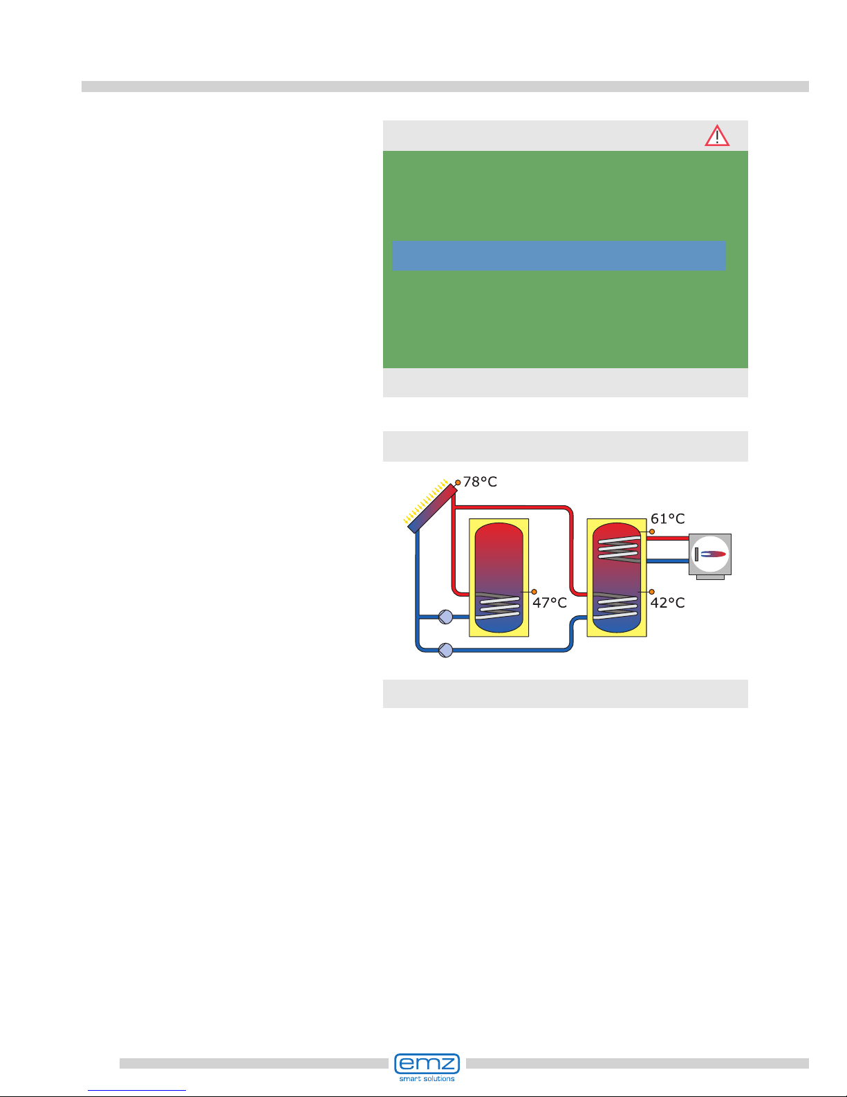
›0.3 Inputs‹ appears.
Select and activate the input interfaces TS1 to TS8 used and assign the
selected function to them by scrolling.
Once all inputs have been assigned
correctly, acknowledge by pressing
›Next‹.
Important!
At the interfaces TS6 / TS7 / TS8 an impeller sensor
can be selected as owmeter via ›Impeller‹.
›0.2 Time/date‹ appears.
Press ›OK‹ - the hour is highlighted in
colour.
Turn the rotary encoder until the
correct gure appears, and
acknowledge via the ›OK‹ button.
The controller accepts the value
and jumps to the minute setting.
In this way, all values for time and
date
can be entered.
If the differential temperature controller is installed at a location where
daylight-saving time exists, the time
shift can be activated here.
Acknowledge by pressing ›Next‹.
Date
Time
Automat. Clock Change
25.08.2012
09:12
Next
0.2 Time/Date
25.08.2012 09:12
TS1
TS2
TS3
TS4
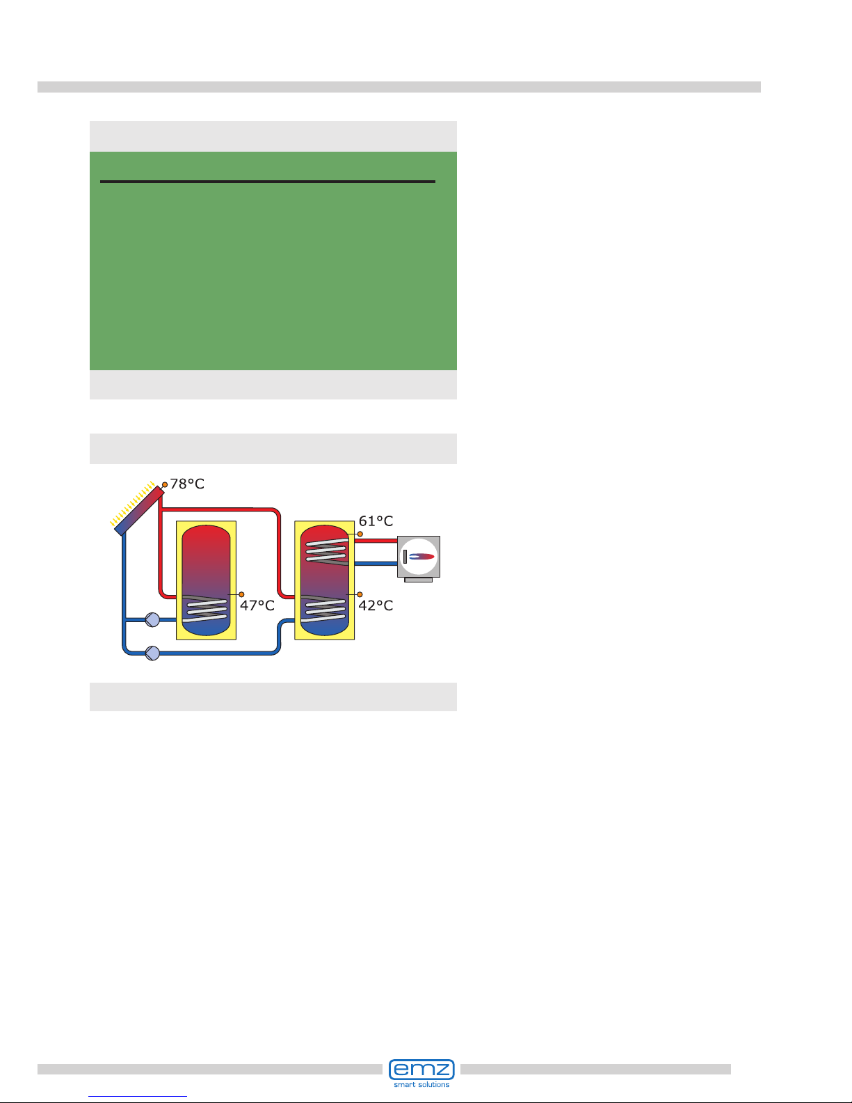
77.6°C
Collector 1
46.7°C
Tank1 bottom
42.2°C
Tank2 bottom
61.4°C
0.3 Inputs
25.08.2012 09:12

59
Commissioning mode
›0.5 Outputs‹ appears.
Select and activate the output interfaces RO1 - RO4 / REL used and
assign them to the selected function
by scrolling.
Once all outputs have been assigned
correctly, acknowledge by pressing
›Next‹.
›0.4 Volumetric ow‹ appears.
If TS6 / TS7 / TS8 has already been
assigned to ›Impeller‹, ›Impeller‹ will
appear here in terms of sensor system. The number of pulses per litre
still has to be selected.
If different features (or no features)
are assigned to TS6 / TS7 / TS8, a
vortex sensor or a ow rate detector
can be selected via pump
activation. To this effect, the vortex
volumetric ow sensor installed or the
max. pump ow rate still have to be
dened.
Acknowledge by pressing ›Next‹..
Important!
A high-efciency pump can be connected to TS7 to TS10.
The WILO ST 25/7 PWM is preassigned.
Vortex UI12
Flow rate
connected to
Grundfos 1-12l/min
RO2
Next
0.4 Volumetric flow
25.08.2012 09:13
RO1
HE-control signal
RO2
RO3
RO4
REL
Solar pump 1
---
---
---
---
---
Next
0.5 Outputs
25.08.2012 09:13
60
Commissioning mode
›0.7 Checklist‹ appears.
Here, the submenus Test outputs and
Holiday function are made available.
By selecting ›SP 1 (top), a scrollbox
is displayed in which an appropriate
input (TS1 - TS8) can be assigned.
Select Test outputs and activate
by pressing the OK button.
Now, the controller offers the hydraulic systems which are possible due to
the assigned inputs and the selected
outputs.
By turning the rotary encoder, the
required system can be selected
(here system 1 of 3 possible ones)
and acknowledged via the button
›OK‹.
Note!
Here, access to all plant layouts is possible for testing purposes
via the option ›Show all‹. However, for correct operation, one of
the plant layouts suggested by the controller must be selected.
System 1/3
25.08.2012 09:13
Test outputs
Holiday function
Tank 1 top
Next
0.7 Checklist
25.08.2012 09:14
61
Commissioning mode
›0.7 Checklist‹ reappears.
As the plant, when not in use, is only
supplied with heat, but no heat is
withdrawn, it may be subject to
overheating and damage.
Thus, a ›holiday function‹ was
programmed which minimizes
heat input.
Here, the holiday function can be set -
call up by pressing the ›OK‹ button.
›0.8 Test outputs‹ appears.
Here, the outputs can be activated
manuallyvia the ›OK‹ button to test
the function of the activated output or
of the connected unit.
If not all pumps and valves are working properly, the plant elements in
question and the cabling must be
veried and repaired.
Acknowledge by pressing ›Next‹.
RO1
RO2
RO3
RO4
REL
Next
0.7.1 Test outputs
25.08.2012 09:14
Test outputs
Holiday function
Tank 1 top
Next
0.7 Checklist
25.08.2012 09:14
62
Commissioning is complete.
As of this point, the smart Sol plus
controls the solar thermal plant
automatically.
›0.7 Checklist‹ reappears.
Acknowledge by pressing ›Next‹.
›0.9 End‹ appears.
By ›Next‹, the controller
changes over to ›Automatic mode‹.
Various options can be selected
for the holiday function.
At lower ambient temperatures
(e. g. at night), tank recooling tries
to dissipate heat via the collectors.
The soft charge circuit is designed so
that the heat input into the tank is as
low as possible.
The appropriate switch-ON and OFF
temperatures must be varied as
required.
Acknowledge by pressing ›Next‹.
Commissioning mode
Tank recooling
Soft charge
T-ON
T-OFF
120.0°C
100.0°C
Next
0.7.2 Holiday function
25.08.2012 09:14
You have completed
commissioning!
Next
0.9 End
25.08.2012 10:15
System 11
25.08.2012 09:16
63
Automatic mode
In automatic mode, the screen
displays the date, the time and
the active hydraulic system.
The current temperature is displayed
for each temperature sensor.
The pump activity is displayed
on the display as animation.
There is no need for intervention
by the tter or operator.
Note!
Check the display screen of the smart Sol plus on a regular
basis to be able to eliminate any malfunctions promptly!
System 11
25.08.2012 09:17

64
Operation mode
On the controller, the user can make
various settings and obtain information about states and processes.
To this effect, press the button
›OK‹ in automatic mode.
›1 Main menu‹ appears.
A list of subitems appears
By scrolling ...
...the lower part of
the menu is displayed.
Once the rst subitem
›Evaluation‹ is selected, ...
System 11
25.08.2012 10:19
Evaluation
Settings
Basic functions
Efciency functions
Protective funct.
Monitoring
Login
1 Main menu
25.08.2012 10:19
Settings
Basic functions
Efciency functions
Protective funct.
Monitoring
Login
About smartSol
1 Main menu
25.08.2012 10:19
65
Operation mode
...›1.1 Evaluation‹ appears.
Another selection level appears.
Once the rst subitem
›Measured values‹ is selected, ...
...›1.1.1 Measured val...‹ appears.
Here, the temperatures and
dates concerning the controller
are displayed.
If additional tank sensors have
been dened on commissioning,
these measurands also appear here.
Return to ›1.1 Evaluation‹.
Once the second subitem
›Service hours‹ is selected, ...
...›1.1.2 Service hours‹ appears.
The operating time of the activated
plant components is displayed in
hours.
By actuating the menu item ›Reset‹,
all counters are reset to zero.
The values are saved once per day,
so that one day max. is „lost“ in
case of failure of the power supply.
Return to ›1.1 Evaluation‹.
Once the third subitem
›CO2 savings‹ is selected, ...
Measured values
Service hours
CO2 savings
Heat quantities
Error list
1.1 Evaluation
25.08.2012 10:20
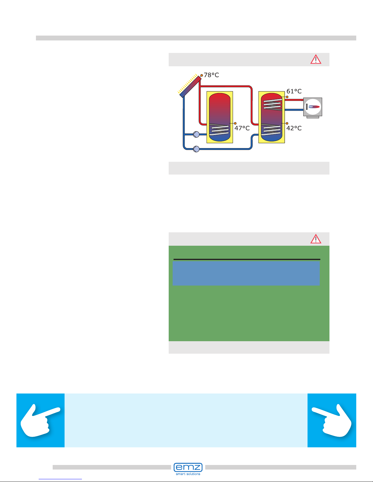
Collector temperature1
Tank 1 bottom temp.
Tank 2 bottom temp.
Tank 1 top temp.Solar
Solar pump 1
Solar pump 2
Boiler
78.2°C
47.0°C
42.1°C
61.4°C
80%
34%
OFF
1.1.1 Measured values
25.08.2012 10:20
Solar pump 1
Solar pump 2
Boiler
Reset
112h
94h
361h
1.1.2 Service hours
25.08.2012 10:21

66
Operation mode
...›1.1.3 CO2 savings‹ appears.
Here, assessment of the saved carbon
dioxide can be activated, read and
reset.
By selecting ›Fuel‹...
...›Edit‹ appears.
Here, the fuel types natural gas or
fuel oil can be selected for a calculation of CO2.
Return to ›1.1 Evaluation‹.
Continue with ›Heat quantities‹.
›1.1.4 Heat quantities‹ appears.
Up to four heat counters can be
congured for the collection of
the generated energy quantity.
The evaluation period can be selected
via the ›Diagram‹ - ›Week‹, ›Month‹
or ›Year‹
Press ›Reset‹ to reset
the counter to 0.
Activation
CO2 Savings (calc.)
Reset
Fuel
447 kg
Natural gas
1.1.3 CO2 savings
25.08.2012 10:21
Fuel
Restore last value
Factory settings
Natural gas
Edit
25.08.2012 10:15
Heat qty. 1
Heat qty. 2
Heat qty. 3
Heat qty. 4
Diagram
Reset
1.1.4 Heat quantities
25.08.2012 10:22
Week

67
Operation mode
The evaluation appears
as a bar graph.
Selecting a submenu,
e.g. ›Heat qty. 1‹...
150
125
100
75
50
25
0
7d [kWh]
1.1.4 Heat quantities
25.08.2012 10:22
...will access ›1.1.4.1 heat qty. 1‹
Activation will start a counter
which calculates heat yield.
›Volume ow‹ denes the volume
ow sensor to be used.
Return and feed sensors are assigned.
In addition to the operation mode’s
functions, the sensors in the return
and supply lines are assigned.
›Efcient tank-charge‹ denes
whether this heat quantity is
used for efcient buffer charge.
›Add to overall HQ‹ adds each
heat quantity to the overall counter.
Continue with ›Error list‹.
Activation
Heat quantity (calculated)
Volume ow
Return line sensor
Supply line sensor
0 kWh
---
---
---
1.1.4.1 heat qty. 1
25.08.2012 10:22
Return line sensor
Supply line sensor
Glycol type
Efcient tank-charge
Add to overall HQ
---
---
Water
1.1.4.1 heat qty. 1
25.08.2012 10:22

68
Operation mode
›1.1.5 Error list‹ appears.
Here, a table of the last errors
occurred appears for information.
By selecting a fault ...
... the error message
appears in plain text.
If necessary, take the
appropriate measures.
Return to ›1 Main menu‹.
Continue with ›Settings‹.
›1.2 Settings‹ appears.
Another selection level appears.
Once the rst subitem
›Date/Time‹ is selected, ...
M33: 4:31 03.07
M32: 6:44 03.07
M05: 7:01 03.07
---
---
---
---
1.1.5 Error list
25.08.2012 10:22
M05:
Sensor short-circuit
on TS3!
Press ESC to return
1.10 Error list
25.08.2012 10:22
Date/Time
Language
Display
Remove SD card safely
Factory settings
1.2 Settings
25.08.2012 10:23

69
Operation mode
...›1.2.1 Date settings‹ appears.
Here, date and time can be set in
case of deviation or an extended
period of deenergizing.
If the differential temperature controller is installed at a location where
daylight-saving time exists, the time
shift can be activated here.
Select the subitem
›Date‹ or ›Time‹ by pressing ›OK‹.
One group of gures each is activated
and can be varied via the rotary encoder; whenever ›OK‹ is pressed, the
activation
jumps to the next group.
Return to ›1.2 Settings‹.
Continue with ›Language‹.
›1.2.2 Language‹ appears.
Here, the user can change over
to another available language.
Continue with ›Display‹.
Date
Time
Automat.Clock Change
25.08.2012
10:23
1.2.1 Date setting
25.08.2012 10:23
Date
Time
Automat.Clock Change
25.08.2012
10:23
1.2.1 Date setting
25.08.2012 10:23
Deutsch
English
Français
Italiano
Česky
Español
Polski
1.2.2 Language
25.08.2012 10:23

70
Operation mode
Before the SD card can be removed,
›Remove SD card safely‹ must have
been selected.
The last menu item is
›Factory settings‹.
By selecting and pressing the
button ›OK‹, followed by ›esc‹,
the preset values are deleted and
replaced by the factory settings.
Return to ›1 Main menu‹.
Continue with ›Basic functions‹.
›1.3 Basic functions‹ appears.
Another selection level appears.
Once the rst subittem
›Thermostat‹ is selected, ...
›1.2.7 Display‹ appears.
›Brightness‹ serves to adjust the
backlighting of the display in steps
of 5% from 10% to 100%.
›Blanking time‹ is used to determine
the time after which, in case of inactivity, backlighting is reduced from the
set value to 10%. Adjustable in the
range from 30 to 255 seconds.
Return to ›1.2 Settings‹.
Brightness
Blanking time
100%
180s
1.2.7 Display
25.08.2012 10:23
Date/Time
Language
Display
Remove SD card safely
Factory settings
1.2 Settings
25.08.2012 10:24
Thermostat
Tube collector
Holiday function
Delta T control
Fixed T control
Post Heating Request
Increase return T
1.3 Basic functions
25.08.2012 10:25

71
Operation mode
...›1.3.1 Thermostat‹ appears.
The controller‘s free outputs can
be used as thermostats for various
applications.
In professional mode, presettings
must be made to this effect - your
tter will explain the appropriate
function to you, if necessary.
By selecting a subitem ...
...the appropriate activation
screen is displayed.
Return to ›1.3 Basic functions‹.
Continue with ›Tube collector‹.
›1.3.2 Tube collectors‹ appears.
This option is to be activated in case
vacuum tube collectors are used.
Return to ›1.3 Basic functions‹.
Continue with ›Holiday function‹.
Thermostat RO3
Thermostat RO4
1.3.1 Thermostat
25.08.2012 10:25
Activation
1.3.1 Thermostat RO3
25.08.2012 10:25
Activation
1.3.2 Tube collector
25.08.2012 10:25

72
Operation mode
›1.3.3 Holiday funct...‹ appears.
Here, you enter the time of your next
holiday. “Holiday” means that the
heating/
warm water plant is not used in summer.
In this case, the controller will adapt
control for the specied period so that
overheating of the plant is prevented.
First select the subitem ›Start‹,
then ›End‹ by pressing ›OK‹.
›Edit‹ appears.
Here, the dates of your absence are
entered. Return to ›1.3 Basic functions‹.
Continue with ›Delta T control‹.
›1.3.5 dT control‹ appears.
Here, parameters of the
controller can be changed.
The factory settings of the
smart Sol plus can be used
for almost all plants.
Ask a tter before making
changes at this point.
Return to ›1.3 Basic functions‹.
Continue with ›Fixed T control‹.
Start of holiday
End of holiday
19.07.2013
02.08.2013
1.3.3 Holiday function
25.08.2012 10:26
Start of holiday
Restore last value
Factory settings
19.07.2013
Edit
25.08.2012 10:26
dT-ON 1
dT-OFF 1
8.0k
4.0k
1.3.5 dT control
25.08.2012 10:27

73
Operation mode
›1.3.6 Fixed temp.c...‹ appears.
Here, the temperature values for
the collector panels are entered which
are to be achieved via control of the
pump delivery rate in question.
The factory settings of the
smart Sol plus can be used
for almost all plants.
Return to ›1.3 Basic functions‹.
Continue with ›Increase return T‹.
›1.3.10 Post Heatin...‹ erscheint.
The reheating control reacts to the
values of the top tank sensor. If the
temperature falls below ›t charge‹
minus the hysteresis, the control
activates the reheating cycle via the
heating boiler. When the set value
is reached the reheating cycle is
stopped.
Return to ›1 Main menu‹.
Continue with ›Efciency functions‹.
›1.3.8 Increase retu...‹ appears.
Parameters for return ow
temperature increase can
be dened here.
Ask a tter before making
changes at this point.
Return to ›1 Main menu‹.
Continue with ›Post Heating Request‹.
T-xed 2
70.0°C
1.3.6 Fixed temp.cont...
25.08.2012 10:27
Activation
T ON
T OFF
T min
8.0K
4.0K
15.0°C
1.3.8 Increase return ...
25.08.2012 10:27
Hysteresis
Time block 1
Time block 2
Time block 3
Time block 4
Time block 5
Time block 6
10.0K
1.3.10 Post Heating R...
25.08.2012 10:27
74
Operation mode
›1.4 Efciency funct...‹ appears.
Another selection level appears.
Once the rst subitem
›disable recharge‹ is selected, ...
›1.5 Protective funct.‹ appears.
Another selection level appears.
Continue with ›Collector defrost.‹.
... ›1.4.3 disable recha...‹ appears.
This option must be activated if
recharging of the warm water tank
is to be switched off as a function of
time or temperature.
To this effect, the tter must
make the appropriate presettings.
Return to ›1 Main menu‹.
Continue with ›Protective functions‹.
Disable recharge
1.4 Efficiency functions
25.08.2012 10:28
Activate time program
Activate T-min
Activat.Tmin oat
1.4.3 Disable recharge
25.08.2012 10:28
Collector defrosting
Tank cooling
Soft charge
1.5 Protective funct.
25.08.2012 10:29

75
Operation mode
›1.5.2 Defrosting‹ appears.
›Defrosting‹ can be used
to heat frozen collectors.
At the same time, the tank is cooled!
This is a one-time action which
must be repeated as required.
Return to ›1.5 Protective functions‹.
Continue with ›Tank cooling‹.
›1.5.5 Cooling funct.‹ appears.
This option must be activated if,
during a heat wave, the heat input
exceeds the energy withdrawal.
In this case, the controller cools the
tank via the collectors, e. g. at night.
Return to ›1.5 Protective functions‹.
Continue with ›Soft charge‹.
›1.5.6 Soft charge‹ appears.
This option should be activated if an
extended spell of hot, sunny weather is to be expected. Thus, the heat
input in the tank is reduced.
Return to ›1 Main menu‹.
Continue with ›Monitoring‹.
Activation
1.5.2 Defrosting
25.08.2012 10:29
Activation
1.5.5 Cooling funct.
25.08.2012 10:29
Activation
1.5.6 Soft charge
25.08.2012 10:29

76
Operation mode
›1.6 Monitoring‹ appears.
Here, the error list can be called up.
The required information
appears on the display.
Return to ›1 Main menu‹.
Continue with ›Login‹.
›1.8 AQA solar‹ appears.
This menu is only occupied if the soft
water station ›AQA solar‹ made by
BWT is integrated in the fresh water
heating.
For appropriate information,
please refer to the documentation
by BWT / regarding AQA solar.
Return to ›Main menu‹.
Continue with ›About smart Sol‹.
›1.7 Login‹ appears.
Here, the tter can enter his/her ac-
cess code to perform further settings
and changes.
Return to ›1 Main menu‹.
Continue with ›AQA solar‹.
Error list
1.6 Monitoring
25.08.2012 10:29
Access code
0
1.7 Login
25.08.2012 10:29
Soft water
Flow rate
Soft water delivery
recent regeneration
Salt consumption
421l/h
317m3
24.08.2012 09:00
66g
1.8 AQA solar
25.08.2012 10:30
77
Operation mode
›1.9 About‹ appears.
Here, the software and hardware
version of the controller, the
serial number and the date of
commissioning appear.
This information is required for
repairs and for version management.
If no entry is made within the
preset time (30 - 255 s) on the
smart Sol plus, the display returns
to ›System‹.
›esc‹ is used to return to the home
screen from every menu.
smartSol
SW version
HW version
Serial number
Commissioning
11.42
3.01
16009
24.08.2012
1.9 About
25.08.2012 10:30
System 11
25.08.2012 10:31
78
Malfunction
The screen on top right shows
the ›Attention‹ symbol which
points out a notication or an
operating malfunction.
Select via ›OK‹.
If ›Safety function‹ appears in
the display, this is a message,
no malfunction.
In this case, there is no deciency,
but limits have been exceeded.
The controller indicates that a
protective function has been
triggered.
The message is only active until
normal operation has been restored.
Note!
If a malfunction message appears in the display, the operator
can dene the possible causes by means of the Service Wizard
so that he/she can provide the tter with precise information.
System 11
25.08.2012 10:32
Safety function
Solar circuit
emergency cut-off
1.10 Service Wizard
25.08.2012 10:32
79
Malfunction
›1.10 Service Wizard‹ appears.
The malfunction appears in plan text
- here:
›M02: Breakage of sensor on TS1!‹.
If an analysis/repair is not
required at present, press ›Menu‹
to return to the main menu.
Danger!
Mortal danger due to electrocution!
For troubleshooting on the plant, disconnect all poles of the power
supply reliably and protect it them against being switched on again!
The differential temperature controller smart Sol plus communicates malfunction
processes in plain text. The Service Wizard indicates the possible causes of
malfunctions on the basis of the detected symptoms and thus supports
immediate and comfortable detection of deciencies.
There may be various deciencies in a solar thermal system, which require
a wide variety of approaches. The controller communicates every step to
the operator or tter via the screen, so that there is no need to describe
all malfunctions in detail in this operating manual.
Here, a malfunction message with troubleshooting process is presented as an example.
M02:
Breakage of
sensor on TS1!
Menu Next
1.10 Service Wizard
25.08.2012 10:33
80
Malfunction
The controller here provides the troubleshooting instruction to check the
connection cable.
Perform the measure in accordance
with the recommendation.
Acknowledge by pressing ›Next‹.
For this malfunction, the following
causes are assumed:
›Cable/connection‹ or ›Sensor‹ -
select the rst menu item and
conrm by pressing ›OK‹.
The Service Wizard helps detect
possible causes of malfunctions.
Acknowledge by pressing ›Next‹.
M02:
Breakage of
sensor on TS1!
Menu Next
1.10 Service Wizard
25.08.2012 10:33
Possible reasons:
Cable/connection
Sensor
Exit
1.10 Service Wizard
25.08.2012 10:33
Please check the
connection cable
to the sensor.
Next
1.10 Service Wizard
25.08.2012 10:33

81
Malfunction
Repair information appears.
Perform the appropriate repair work.
Exit the ›Service Wizard‹
by pressing ›Exit‹.
More detailed instructions
are available if required.
Acknowledge by pressing ›Next‹.
The troubleshooting
result is interrogated.
Continue via ›Yes‹ for the case that
the malfunction has been determined.
Disconnect it
and measure
its resistor.
Next
1.10 Service Wizard
25.08.2012 10:33
Could you detect
a short-circuit /
cable break?
No Yes
1.10 Service Wizard
25.08.2012 10:33
Please replace
the cable.
Exit
1.10 Service Wizard
25.08.2012 10:33
82
Malfunction
Appropriate instructions appear
for each source of faults.
Perform the measure in accordance
with the recommendation.
Continue with ›Explanation‹.
If the cause of the malfunction
has not yet been determined,
troubleshooting can be continued.
Continue with ›No‹.
Select all the sources of malfunctions
listed, and conrm via ›OK‹.
Could you detect
a short-circuit /
cable break?
No Yes
1.10 Service Wizard
25.08.2012 10:33
Possible reasons:
Cable/connection
Sensor
Exit
1.10 Service Wizard
25.08.2012 10:34
Please check
the sensor for
plausible values.
Explanation
1.10 Service Wizard
25.08.2012 10:34

83
Malfunction
After description of the troubleshooting measure, the result determined by
you is interrogated...
A part of the information and
instructions may be provided
in close detail, so that ...
...the texts may well
take several screens.
Disconnect it
and measure
its resistor.
Next
1.10 Service Wizard
25.08.2012 10:34
With PT 1000 sensors
0°C to 100°C
correspond to
a resistor of
1000 to 1385 Ohm.
Is your measured
value within
1.10 Service Wizard
25.08.2012 10:34
correspond to
a resistor of
1000 to 1385 Ohm.
Is your measured
value within
Yes
No
1.10 Service Wizard
25.08.2012 10:34
84
Malfunction
... and the appropriate logical
conclusion is made, the repair
work displayed.
After elimination of the malfunction,
the plant screen without the
›Attention‹ symbol appears
again on the display,
automatic mode is continued.
Sensor is faulty and
must be replaced.
Exit
1.10 Service Wizard
25.08.2012 10:34
System 11
25.08.2012 10:38
85
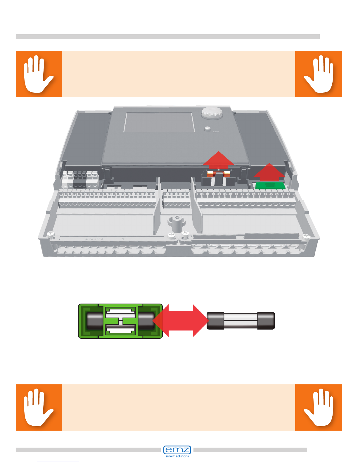
Replacement of fuse
To remove the device fuse, open the terminal cover.
Above the right-hand group of terminals, the fuse base and a spare fuse are
located. Pull the upper part of the support and the spare part out.
The fuse link is clamped in the formed piece and is removed together with the plastic
holder.
Now, push the micro-fuse laterally out of its holder.
The fuse link is installed by reversing the above order.
Make sure to procure yourself immediately a new spare fuse!
Danger!
Mortal danger due to electrocution! Before opening
the terminal cover, disconnect the power supply reliably!
Danger!
Risk of re due to overload or short-circuit!
Only use fuse links type 5 x 20 mm, T4A!

86
Professional mode
Important!
In professional mode, settings are made which require detailed
knowledge of the heating and solar plant.
Moreover, solid specialist knowledge regarding control
engineering, hydraulics and solar thermal water heating is required!
If a single parameter is changed, this may affect the safety,
function and efciency of the entire plant!
Leave the settings in professional mode to a
specialist workshop, the tter or heating installer!
Modications by non-experts tend to result in damage to
the plant, rather than to an improvement of its efciency!
To enter the professional mode, select
›1.7 Login‹ from the main menu,
activate and ...
... enter the access code.
The access code to
professional mode is ›365‹.
The fact that the tter must be
available for his/her customers
on 365 days per year may serve
as a mnemonic trick.
Access code
0
1.7 Login
25.08.2012 10:29
Access code
Restore last value
Factory settings
365
Edit
25.08.2012 10:31

87
Professional mode
After having returned to ›1 Main
menu‹,the screen shows a list of
subitems as in operation mode.
The menu ›1.1 Evaluation‹ is
identical to the operating mode.
The following items appear under
›1.2. Settings‹ next to the operation
mode menus:
- ›Temp. limitation‹
- ›Max.temp.shutoff‹
- ›Min. temperature‹
- ›Priority charging‹
Call up menu item ›Temp. limitation‹.
Evaluation
Settings
Basic functions
Efciency functions
Protective funct.
Monitoring
Login
1 Main menu
25.08.2012 10:32
Measured values
Service hours
CO2 savings
Heat quantities
Error list
1.1 Evaluation
25.08.2012 10:32
Date/Time
Language
Display
Tank temp.limitation
Max.temp.shutoff
Min.temperature
Remove SD card safely
1.2 Settings
25.08.2012 10:33

88
Professional mode
If the temperature in tank 1 exceeds
the value T limit 1, or if the temperature in tank 2 exceeds the value
T limit 2, the solar circuit pump is
switched off unconditionally.
The pump is not switched on again
until the actual temperature falls below the value T limit by the hysteresis
›Hyst‹.
Example: T limit =60°C minus Hyst=5K => Reclosing temperature 55°C.
Continue via the menu
item ›Max.temp.shutoff‹.
Maximum temperature of the tanks 1
and 2, to avoid excessively hot water
in the tank; the tank in question is
only charged to its ›T max‹.
In case of collector overheating, the
tank can be charged up to ›T-limit‹.
Continue via the menu item
›Min. temperature‹.
To increase efciency on charging
the tanks, the minimum temperature
to be present at the collector in
question is entered via ›T min. Coll‹.
The relevant hysteresis value
represents the difference
between the switch-ON
and switch-OFF temperature.
Continue via the
menu item ›Priority charge‹.
Hysteresis
T limit 1
T limit 2
If T-limit>60°, anti-scalding
protection must be installed.
5.0K
60.0°C
60.0°C
1.2.3 Temp.limitation
25.08.2012 10:34
T max.tank 1
T max.tank 2
59.0°C
59.0°C
1.2.5 Max.temp.shutoff
25.08.2012 10:34
Activation
T min.Collector 1
Hyst. Collector 1
20.0°C
2.0K
1.2.6 Min. temperature
25.08.2012 10:34

89
Professional mode
In case of dual-tank systems, the tank
to be charged rst is dened: tank 1,
tank 2 or parallel charging.
›t pause‹ is used to set the pause
time between twot switch-ON tests.
›t charge‹ serves to dene the
charging time for the secondary tank.
Once ›dT Coll‹ is reached,
the pause time is restarted.
Continue with ›Basic functions‹.
The following items appear under
›1.3. Basic functions‹ next to the
operation mode menus:
- ›Thermostat‹
- ›Output parameter‹
- ›Collector cooling‹
- ›Post Heating Requ. ...
... and enhanced menus regarding the
- ›Holiday function‹
- ›Delta T control‹
- ›Fixed T control‹
- ›Increase return T‹
Call up the menu item ›Thermostat‹.
Priority
Pause time
Charge time
dT Collector
Tank 1
2min
20min
2.0K
1.2.8 Priority charging
25.08.2012 10:34
Thermostat
Output parameter
Tube collector
Holiday function
Collector cooling
Commissioning
Delta T control
1.3 Basic functions
25.08.2012 10:35
Holiday function
Collector cooling
Commissioning
Delta T control
Fixed T control
Post Heating Request
Increase return T
1.3 Basic functions
25.08.2012 10:35

90
Professional mode
If outputs on the controller are not
assigned, these channels can be
used as thermostats.
Here, the appropriate
channel is selected.
For the heating function,
T ON must be < T OFF.
For the cooling function,
T ON must be > T OFF.
Up to four time slots can be assigned
to each thermostat function.
Dene times for activation
and deactivation.
Continue via the menu item
›Output parameter‹.
Perform activation.
Dene the start signal.
Depending on the selection of ›Start‹,
the following parameters are shown.
The output has already been dened
by the selection - the related sensor
remains to be dened.
Dene switch-ON/OFF temperature.
Continue to scroll.
Thermostat RO3
Thermostat RO4
1.3.1 Thermostat
25.08.2012 10:35
Activation
Start
Sensor
Output
T ON
T OFF
Timer,thermostat
---
RO3
0.0°C
0.0°C
1.3.1 Thermostat RO3
25.08.2012 10:35
t ON 1
t OFF 1
t ON 2
t OFF 2
t ON 3
t OFF 3
t ON 4
00:00
00:00
00:00
00:00
00:00
00:00
00:00
1.3.1 Thermostat RO3
25.08.2012 10:35

91
Professional mode
Here, the general settings for the
assigned outputs are dened.
›t tear-off‹ and ›n tear-off‹ dene
how long and at which speed the
pumps are to run on starting.
Select an output...
60
50
40
30
20
10
0
2 4 6 8 10 12 14
Speed in %
Temperature difference in K
Note!
The ›Speed delta‹ parameter denes the speed change for step control.
Speed is adjusted by each set value by changing the temperature.
Step control is either selected in the ›1.3.5 dT control‹ menu or in the
›1.3.6 Fixed T control‹ menu.
Parameters for the following sample diagram:
n-min = 30% / n-max = 100% / algorithm = dT (menu 1.3.7) /
dT 1 = 2.0K / dT-on 1 = 5.0K / dT-target 1 = 10.0K /
control 1 = stepped (menu 1.3.5) / speed delta = 10% (menu 1.3.7).
Solar pump 1
Solar pump 2
Boiler
Thermostat RO3
Time for tear-off
Speed for tear-off
Speed delta
10s
100%
10%
1.3.7 Output parameter
25.08.2012 10:35

92
Professional mode
To receive correct measured values
from the tube collector system, the
pump must be switched ON briey.
By activation of the function, the
solar circuit pump can be started
time- and/or temperature-controlled.
The time sequence,
the pump ON time and ...
...to dene the required control
algorithm as ›dT‹ or ›Fixed T‹.
In case of plants with long piping or
slow response, overtravel times for
the solar circuit, pump and valve can
be determined.
Continue to menu item
›Tube collector‹.
... the pump delivery rate as a
percentage value can be entered.
The two time programs are
performed one after the other.
Continue via the menu item
›Holiday function‹.
Algorithm, output control
Overtravel time
min. pump speed
max. pump speed
dT
0s
50%
100%
1.3.7 Output parameter
25.08.2012 10:35
Activation
Start
t-ON restart
T-ON restart
t solar 1
n solar 1
t solar 2
time-dependent
10min
20.0°C
20s
100%
0s
1.3.2 Tube collector
25.08.2012 10:35
T-ON restart
t solar 1
n solar 1
t solar 2
n solar 2
Start time
End time
20.0°C
20s
100%
0s
30%
06:00
20:00
1.3.2 Tube collector
25.08.2012 10:35
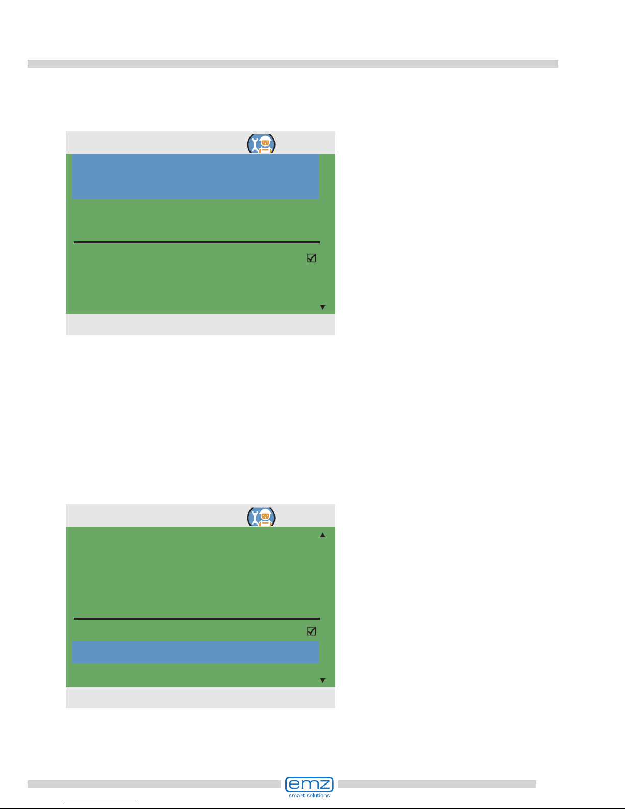
93
Professional mode
Under ›Recooling‹, determine whether
cooling is to be effected down to
›T min tank‹ or ›T max tank‹.
Under ›n pump‹ set the
pump speed in percent.
Enter the hysteresis value by ›Hyst‹.
If necessary, activate ›Soft charging‹
›dT‹ is used to dene the switch-ON
temperature for the holiday function
as a difference from the preset
maximum temperature of the tank.
Continue to scroll.
To avoid overheating of the plant,
the controller will suppress yield
optimization while the holiday
function is activated.
The time frame of the holiday function
is mostly dened in operation mode.
If tank cooling is activated, an
appropriate time frame must be
dened - this makes sense during the
cooler hours of the night - by allowing
the controller to dissipate as much
energy as possible via the collectors.
Continue to scroll.
Start of holiday
End of holiday
Tank cooling
Start
End
19.07.2013
02.08.2013
00:00
07:00
1.3.3 Holiday function
25.08.2012 10:35
Re-cooling
n pump
Hyst.
Soft charge
dT
T-min tank
100%
5.0K
5.0K
1.3.3 Holiday function
25.08.2012 10:35

94
Professional mode
Via ›T-min tank 1‹ and
›T-min tank 2‹, specify the
minimum temperature required
for the tank in question.
Select whether the ›Priority tank‹
or the ›Secondary tank‹ are to be
cooled.
Continue via the menu item
›Collector cooling‹.
Here, collector cooling is activated:
once the collector temperature
›T max. Coll. 1‹, or ›T max. Coll. 2‹ is
reached, the appropriate solar circuit
pump continues to operate until the
tank limit temperature is reached.
To protect the pump, the collector
emergency switch-off in solar circuits
with high-efciency pumps is reduced
to 100°C. Collector cooling is not
possible at higher temperatures!
Return to ›1.3. Basic functions‹.
Continue with ›Commissioning‹.
Here, new commissioning
can be started - e. g. if a new
hydraulic system is to be selected.
=> ›Commissioning mode‹
as of page 61.
Continue with ›Delta T control‹.
Hyst
Soft charge
dT
T min.tank1
T min.tank2
Tank
5.0K
5.0K
45.0°C
45.0°C
Priority tank
1.3.3 Holiday function
25.08.2012 10:35
Activation
T max.Collector 1
121.0°C
1.3.4 Cooling funct.
25.08.2012 10:36
You really want to
start commission.?
No Yes
0 Welcome
25.08.2012 10:36

95
Professional mode
If control algorithms have been
dened as ›dT‹ under ›1.3.7 Output
parameter‹, the appropriate outputs
can be congured here.
Via ›dT ON‹, the switch-ON
temperature, via ›dT OFF‹, the
switch-OFF temperature and via
›dT targ.‹, the target differential
temperature are set. (Differential
temperature between collector
and tank, bottom).
Continue with ›Fixed T control‹.
If control algorithms have been
dened as ›Fixed T‹ under ›1.3.7
Output parameter‹, the appropriate
outputs can be congured here.
In case of the xed temperature
control, the collector is controlled to
the preset temperature via a variable
pump delivery rate.
Continue with ›Post Heating Request‹.
Note!
The ›dT targ.1‹ parameter is displayed in the
›1.3.5 dT control‹ menu for systems with 2 collector elds.
With ›dT targ.1‹ the maximum temperature
difference between both collector sensors is specied.
Once this value is exceeded, the pump of the „colder“ collector eld
is deactivated in order to increase efciency.
Activation dT 1
dT 1
dT-ON 1
dT-OFF 1
dT targ.1
Contl 1
2.0K
8.0k
4.0k
10.0K
step-wise
1.3.5 dT control
25.08.2012 10:37
Control 2
Variant 2
T-xed 2
step-wise
70.0°C
1.3.6 Fixed temp.cont...
25.08.2012 10:37

96
Professional mode
Here, reheating can be activated.
The boiler is dened as ›Solid-fuel
boiler‹ or ›Gas/oil‹.
In case of solid-fuel boilers reheating
is made via the charge pump of the
drinking water tank and is only
activated if the temperature of the
tank is within the values ›Min. temp.‹
und ›Max. temp.‹.
Use ›Boiler sensor‹ to assign the
temperature sensor which supplies
the temperature value of the boiler.
Up to six time blocks can
be activated for reheating.
›Ref. temp.‹ is used to dene the set
temperature at the top tank sensor.
If the temperature falls below ›Ref.
temp.‹ by ›Hysteresis‹, the control
activates the reheating cycle via the
heating boiler until ›Ref. temp.‹ is
reached.
Each period can be dened with
›Weekends‹, Monday - Sunday‹ or
›Monday - Friday‹.
Continue with ›Efciency functions‹.
Activation
Reference temperature
Starting time
End time
Time period
45.0°C
00:00
23:59
Daily
1.3.10 Post Heating R...
25.08.2012 10:37
Activation
Boiler type
Hysteresis
Minimum temperature
Maximum temperature
Sensor boiler
Solid fuel boiler
10.0K
40.0°C
55.0°C
TS6
1.3.10 Post Heating R...
25.08.2012 10:37
Sensor boiler
Time block 1
Time block 2
Time block 3
Time block 4
Time block 5
Time block 6
TS6
1.3.10 Post Heating R...
25.08.2012 10:37

97
Professional mode
The following items appear under
›1.4. Efciency funct.‹ next to
the operation mode menus:
- ›Low-Flow‹
- ›Quick-charging‹
- ›Efcient tank-charge‹
Call up menu item ›Low-Flow‹.
Tank quick charging changes over
from dT control to xed temperature
control.
›T ON‹ and ›T OFF‹ dene the
change-over range and ›T targ. Coll.‹
the xed temperature on the collector.
An upper tank sensor is
required for quick-charging.
Continue with ›Disable recharge‹.
Here, the switch-ON temperature
can be dened for low-ow plants.
Continue with ›Quick-charging‹.
Low-Flow
Quick-charging
Disable recharge
Efcient tank-charge
1.4 Efficiency functions
25.08.2012 10:38
Activation
T ON
60.0°C
1.4.1 Low-Flow
25.08.2012 10:38
Activation
Sensors
T ON
T OFF
Collector target temp.
---
48.0°C
52.0°C
70.0°C
1.4.2 Quick-charging
25.08.2012 10:38

98
Professional mode
If the plant has been designed accordingly and a system involving disable
recharge selected, the appropriate
parameters are set here.
Here, the time control and/or the
temperature control are activated possible for all systems with heating
boiler control.
Time and temperature control
can be used in combination.
Select the time slot
via ›Start‹ and ›End‹.
Select the minimum temperature
via ›T min tank‹.
Here, the efciency-optimized disable
recharge is enabled and activated -
possible for all systems with heating
boiler control.
Set ›factor 1‹.
Factor 1 assesses solar yield,
factor 2 assesses comfort.
By reducing factor 1, the expected
solar input gets a higher weighting.
Set ›factor 2‹.
Reducing factor 2 will
decrease comfort.
Determine under ›T oating‹ whether
the temperature is to be measured
on the upper or lower tank sensor.
Enter the minimum tank temperature
via ›T min tank‹.
Continue with ›Efcient tank-charge‹.
Activate time program
Start
End
Activat, T-min
T min. tank
Activat.Tmin oat
00:00
00:00
45.0°C
1.4.3 Disable recharge
25.08.2012 10:39
Factor 1
Factor 2
T target
T oating
T min. tank
4.0
2.0
45.0°C
upper tank sensor
45.0°C
1.4.3 Disable recharge
25.08.2012 10:39
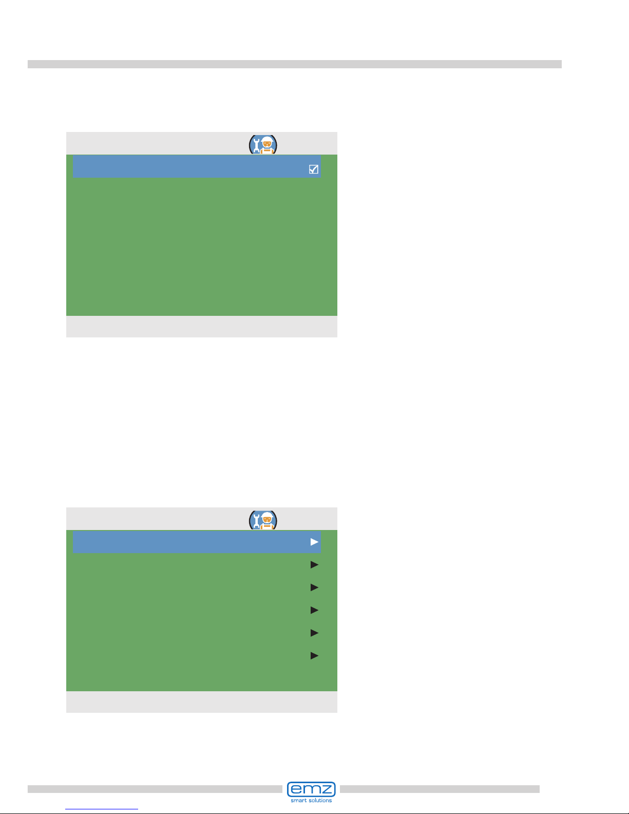
99
Professional mode
The following items appear under
›1.5. Protective funct.‹ next
to the operation mode menus:
- ›Anti-Blocking‹
- ›Anti-legionellae‹
- ›Antifreeze protection‹
Call up menu item ›Anti-Blocking‹.
›Efcient tank charge‹ is
activated and congured here.
The solar circuit pump is controlled
according to the entered heat
quantity. In order to use this
functionality, a heat quantity counter
must be congured in the solar circuit
(=> ›1.1.4 Heat quantities‹ menu).
The ›t delay after t. change‹
parameter denes the time
between two speed changes.
Once the waiting time has expired,
the speed of the solar pump is
increased or decreased by 10%.
With the ›Performance delta‹
parameter, the additional yield
which is necessary during the waiting
time for the pump speed to change
accordingly is set .
Return to ›Main menu‹.
Continue with ›Protective funct.‹.
Activation
t delay after t. change
Performance delta
4.5min
100W
1.4.4 Efficient tank ch...
25.08.2012 10:39
Anti-blocking
Collector defrosting
Antifreeze protection
Anti-legionellae
Tank cooling
Soft charge
1.5 Protective funct.
25.08.2012 10:40

100
Professional mode
›Defrosting‹ can be used
to heat frozen collectors.
At the same time, the tank is cooled!
Set the pump runtime.
Continue with ›Antifreeze protect.‹.
The pumps can be moved daily to
prevent them from getting blocked.
This function is not activated as long
as the pumps are activated in normal
operation.
Determine the time of the
day and the operating period.
Continue with ›Collector defrost.‹.
Start
Duration
11:00
5s
1.5.1 Anti-block protect.
25.08.2012 10:40
Activation
Max. pump t defrosting
5min
1.5.2 Defrosting
25.08.2012 10:41
 Loading...