

emz Smart Sol Assembly & Operation
Equipment ›Top‹

These Assembly and Operating Instructions are an integral part of the product.
> Read Assembly and Operating Instructions carefully before using the product.
> Keep them in a safe place during the product‘s service life.
Translation from the German original edition ©emz 2013 - Subject to modications.
The contents and representations of these Assembly and Operating
Instructions are the intellectual property of emz-Hanauer GmbH & Co.KGaA.
Non-authorized disclosure, reproduction, divulgation or editing of this
documentation, as well as exploitation, utilization or publication, are prohibited.
The rights to the word and design marks ›emz - smart solutions‹ and ›smart Sol‹
are the exclusive property of emz-Hanauer GmbH & Co.KGaA.
The rights to any cited brands, names or logos are the property
of their appropriate developers / of the licensees in question.

3
Table of Contents
Table of contents Page
Important fundamental information 4
Symbols used 5
Description 6
Dimensions 7
Technical Data 8
Designation of the components 10
Operation of the controller 11
Display 12
Opening the terminal cover 13
Wall-mounting 14
Connection to power supply 15
Data interfaces 19
Hydraulic systems 20
Functions for boiler control 45
Thermostat functions 48
Commissioning mode 49
Automatic mode 54
Operation mode 55
Malfunction 70
Professional mode 77
Disassembly/Disposal 98
Warranty and liability 99
Error report 101
EC Declaration of conformity 102
Index 103

4
Important fundamental information
These instructions describe installation, commissioning, operation, repair
and disassembly of the differential temperature controller smart Sol for
solar thermal plants.
For operation of the entire plant, the technical documentation of all the
components used such as solar collectors, boiler, tank, pumps, mixers
and valves etc. must be complied with.
The controller is handled by the operator of the entire solar
thermal plant, i. e. as a rule by technical non-experts.
Make sure not to use the controller until you have thoroughly read and
understood these Assembly and Operating Instructions and the safety provisions.
Comply with all safety provisions and involve a specialist in case of doubt.
Keep these Assembly and Operating Instructions and all reference
documents so that they are available if required.
When relocating or when selling the device, hand the documents over to your successor.
Important!
The tter installing the controller must inform the plant operator about
operation, functioning and the method of action of the smart Sol!
Danger!
The device in operation may only be made accessible to
adults disposing of appropriate knowledge and experience!
Danger!
The controller by no means replaces the safety
components required under plant engineering aspects!
Danger!
Assembly, connection, commissioning, repair and disassembly of
the controller may only be performed by a qualied specialist!

5
Symbols used
When handling the differential temperature controller smart Sol
and the entire plant, please make sure that the following safety provisions
in the Assembly and Operating Instructions are complied with!
Note!
Useful information regarding handling of the device and the plant!
Important!
Important information compliance with which is essential!
Danger!
Immediate danger for assets, life and limb!
6
Description
The differential temperature controller smart Sol is an independent electronic
controller for surface-mounting which is used for the control of solar thermal plants.
The controller is equipped with a robust three-part plastic housing
which can only be opened by means of tools (screw driver PH2).
Operation is effected by means of only two control elements;
indications appear against a backlit colour display.
Before connection of the electrical system, the controller
must be mounted rmly to a perpendicular, robust surface (wall).
For its own supply and the supply of the outputs, the controller must be connected
to an electrical energy supply system in accordance with the technical data.
Assembly, connection, commissioning, repair and disassembly
of the controller are only admissible in a specialist workshop.
To ensure correct operation, temperature sensors type Pt 1000
must be used - the sensor design does not affect function.
Each temperature sensor has two connectors which are equivalent,
i. e. interchangeable. Thus, polarity reversal is not an issue.
The sensor lines can be extended up to a length of 100 m, to
this effect, a cable cross section of 2 x 1.5 mm2 is recommended.
Note!
The electrical equipment of the device must be installed rmly and
connected to the power supply via a disconnector ensuring complete
isolation from the power supply according to the erection regulations!
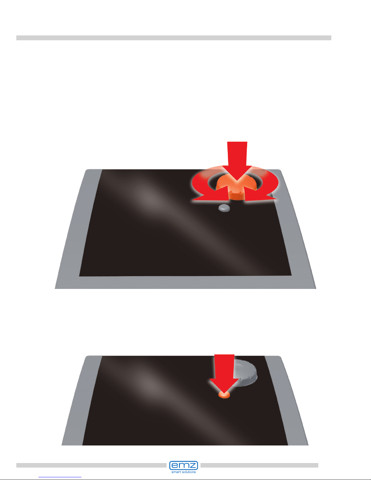
Important!
Make sure that only a dry or slightly moistened cloth is used for cleaning
and servicing of the housing, the control elements and the display.
The surfaces must never get into contact with cleaning products
or solvents - mat, brittle or slightly dissolved plastic parts must
be replaced immediately!
A device with damaged housing must not be operated!
7
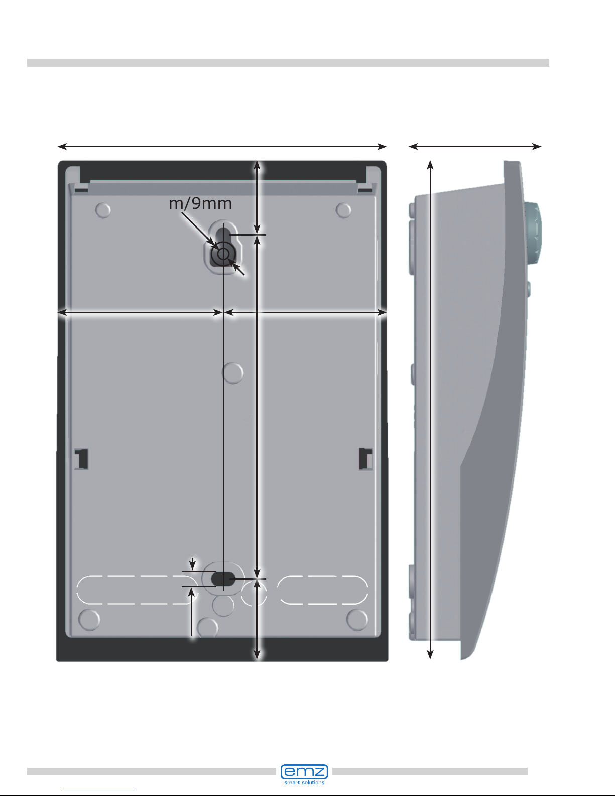
Dimensions
5 mm
57,5 mm
115 mm
d
max
5mm/9mm
120 mm
27 mm
26 mm
57,5 mm
46 mm
173 mm

8
Technical Data
Intended Use
The differential temperature controller may be used exclusively as controller for the con-
trol of solar thermal plants. It must be operated within the scope of all the specications
described. Installation and set-up of the controller may only be performed by specialists.
The tter must have read and understood the operating manual.
The tter explains all the relevant functions to the operator.
For operation, it is essential that the housing is closed and free of damage.
Scope of supplies
1 Differential temperature controller smart Sol
1 Instruction manual
Differential temperature controller smart Sol
Type of mounting Wall-mounting
Housing Plastics, in several parts
Mode of operation Type 1
Type of protection IP 20
Dimensions Width x Height x Depth [mm] 115 x 173 x 46
Weight [g] Basic version 370
Storage/operating temperature [°C] 0-40, non-condensation
Handling via rotary encoder and pushbuttons
Display TFT colour display 47 x 35 mm, backlit
Connection to power supply
Design 3 spring-type terminals PE, N and L
Service voltage [VAC] 230 ±10%
Line frequency [Hz] 50 ±1%
Auxiliary consumption typ. [W] 1,74
Power consumption max. [W] 3.5
Fuse Micro fuse, type 5 x 20 mm, T2A/250 V
Rated pulse voltage [V] 2500
Max. cross sections to be connected
Cable end sleeve: 0.25 to 0.75 mm
2
Single-wire 0.50 to 1.50 mm2
Fine-wired 0.75 to 1.50 mm
2

9
Technical Data
Interfaces TS1 / TS2 / TS3 / TS4 / TS5 / TS6
Design 2 spring-type terminals each
Assignment as inputs
Admissible temperature probe Temperature sensor Pt 1000
Optional assignment of
TS3 / TS4 to the impeller sensor DFZ 1-100 pulses/litre
Optional assignment as
output on TS4 PWM signal 100Hz...2kHz or
analogue output 0...10V, max. 10mA
Interface TS7 / TS8
Design 2 spring-type terminals each
Assignment as output PWM signal 100Hz...2kHz
analogue output 0...10V, max. 10mA
Triac outputs RO1 / RO2
Design 3 spring-type terminals each, PE, N and L
Output voltage [VAC] 230 ±10%
Output power max.
per output [VA] 200
Output current max.
per output [A] 1
Switching output REL: change-over contact
Design 3 spring-type terminals
Switching voltage max. [V] 253
Switching capacity max. [VA] 230
Switching current max. [A] 1
Interface for analogue Vortex ow sensors
Design Plug connector
10
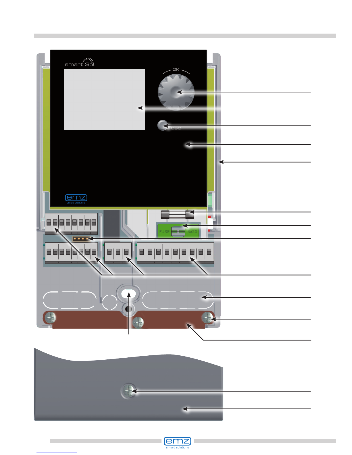
Designation of the components
Drillhole for
securing bolt
Fuse
Housing base
Terminals
Spare fuse
esc button
Display
Rotary encoder
with OK button
Housing cover
Terminal cover
Screw fastening
of terminal cover
Break-out segments
Screw connection
strain relief device
Strain relief device
Vortex plug connector
11
Operation of the controller
The entire set-up and operation of the differential temperature controller
smart Sol is effected via only two control elements on the device front.
All settings and interrogations are effected via the rotary encoder.
To nd a required menu item, turn the rotary encoder to ›scroll‹
through the menu - the selectable option appears on a coloured
background on the display.
To conrm the selected menu item, press the rotary encoder.
An appropriate submenu is called up, or selection is activated.
Press the esc button to make the menu return by one level from any subitem.
If no input is made within the preset time (30-255 s),
the controller returns automatically to the initial level.
12
System 1
04. 07. 2012 10:35
Display elements; example: information screen
Display
For indication of the operating mode and for communication in case of set-up,
malfunction, modication and evaluation, the differential temperature controller
smart Sol is equipped with a coloured full graphics display which is permanently backlit.
The display is active as long as there is supply voltage on the controller.
After a preset time (30 - 255 s), backlighting is dimmed to 10%.
Active system
with current
temperatures
Date and time
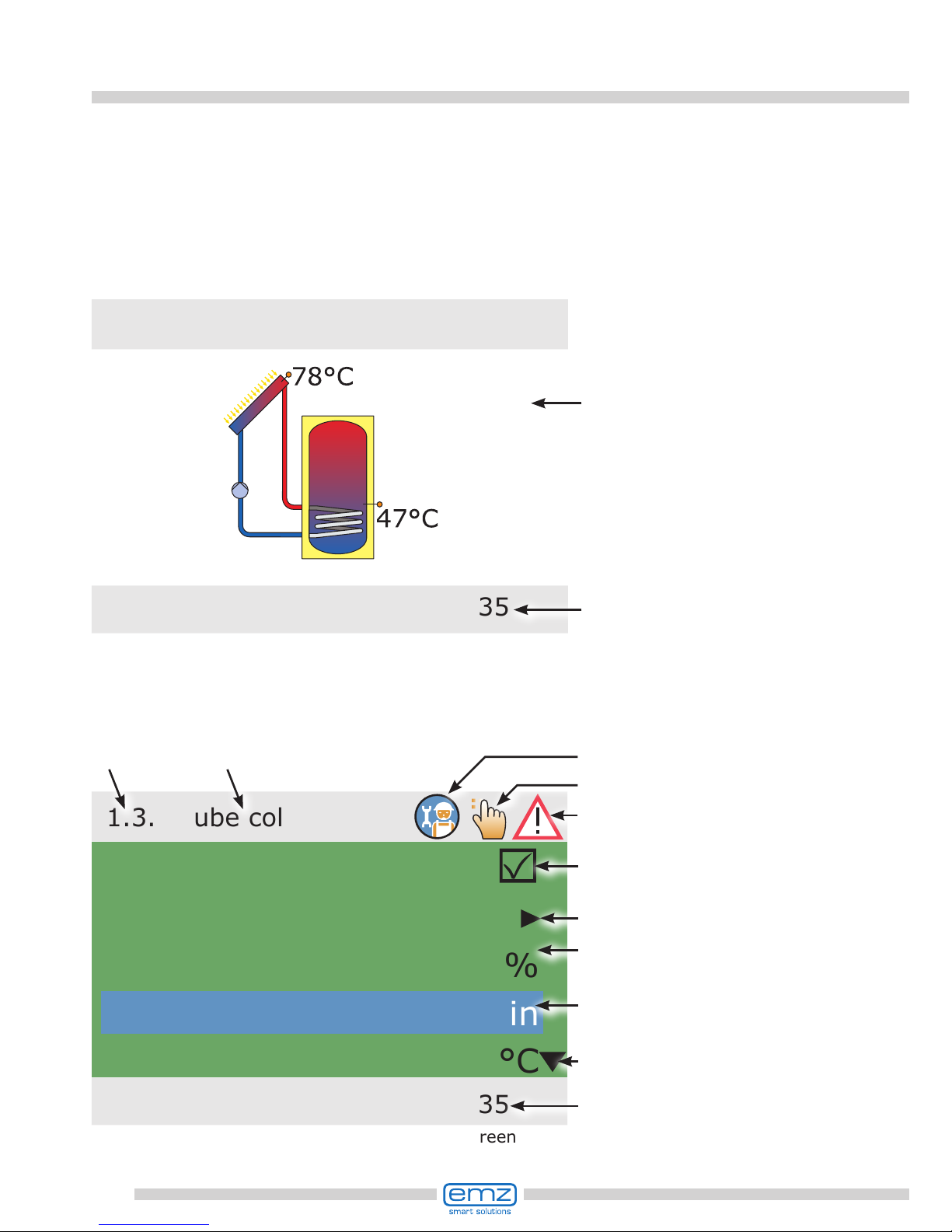
Display elements; example: communication screen
1.3.2 Tube collector
04. 07. 2012 10:35
Activation
Start
n solar 1
t start
T start
80%
10min
20.0°C
Activatable
menu item
Selection menu
Scroll arrow
Check box
Sub menu arrow
Date and time
Professional mode
Manual mode
Message
Number and name of menu
13
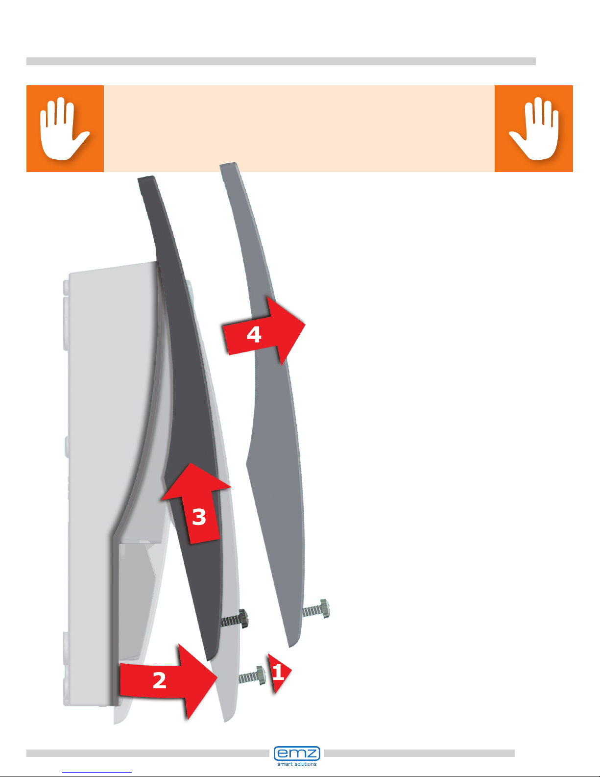
Danger!
Mortal danger due to electrocution! Whenever work is performed on the
open terminal cover, all poles of the power supply must be
disconnected reliably and protected against being switched on again!
Opening the terminal cover
1 Release the lock screw.
2 Swing terminal cover
forward ...
3 ... push it upwards ...
4 ... and remove it.
Store the terminal cover
carefully and protect
it against damage!
To close the terminal cover,
reverse the opening procedure.
14
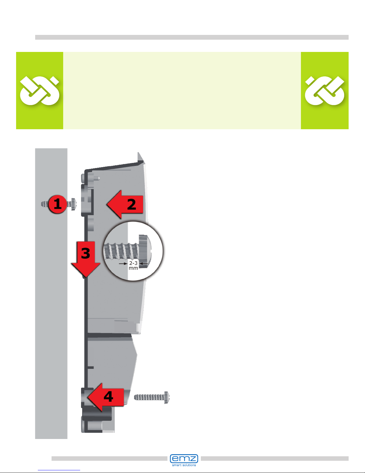
Wall-mounting
1 Fasten the top securing bolt so
that a space of 2 to 3 mm is
created between the wall and
the screw head.
2 Move the device so that the
upper fastening port is located
above the screw head ...
3 ... and push it downwards.
4 Fasten the lower securing bolt.
If necessary, use dowel
pins for wall-mounting!
Important!
The device corresponds to protection type IP 20 - make sure the
appropriate prerequisites exist on the envisaged place of installation.
Do not use the housing base as drill template.
A device with damaged housing must not be operated!
15
Connection to power supply
Danger!
Mortal danger due to electrocution! Whenever work is performed
on the open terminal cover, all poles of the power supply must be
disconnected reliably and protected against being switched on again!
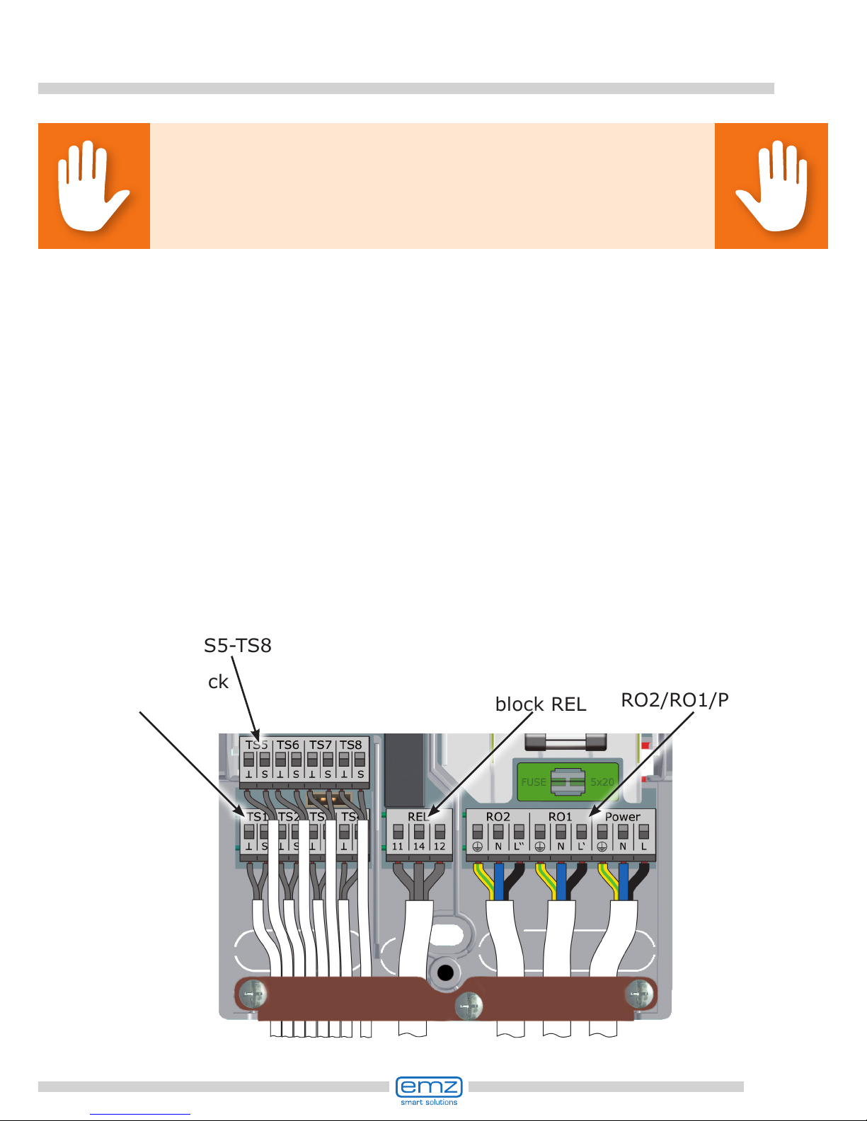
Terminal block
RO2/RO1/Power
Terminal
block REL
Terminal block
TS5-TS8
Terminal block
TS1-TS4
The differential temperature controller smart Sol is connected to the
power supply four three groups of spring-type terminals which are
visible once the terminal cover is opened.
To introduce the cables, release the three screws on the strain relief device;
if necessary, remove the strain relief device.
In case of ush mounting of the cables, the break-out segments in the housing
base can be removed carefully and the cables routed through these ports.
The central terminal block is the interface to a potential-free change-over
contact - here, it may be necessary to route electrical resistors into the
spring-type terminals and to connect part of the cables via luster terminals.
The spring-type terminals for the power supply, RO1, RO2 and REL, and for
TS1 to TS8 can accommodate solid wires up to a cross section of 1.5 mm2.
Appropriate stranded wires must be preassembled with cable end sleeves.
For the strain relief device function, TS1 to TS7 and REL require
cable cross sections of at least 5mm, for Power, RO1, RO2 at least 7mm.
16
Connection to power supply
Connection of a pump to REL
Connection diagram for a pump to REL:
L
N
PE
L
N
PE
Pump
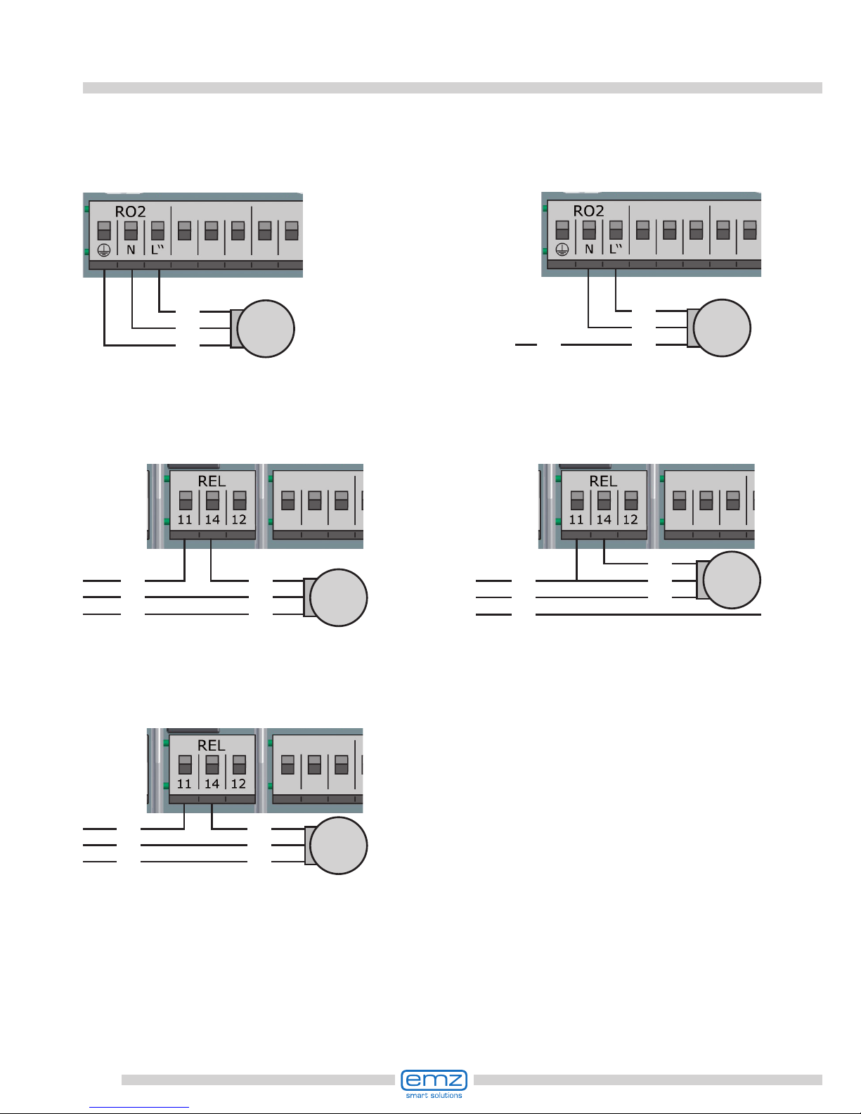
Connection of a switching valve to RO1/RO2
Connection diagram for a switching Connection diagram for a switching
valve without power supply to RO2: valve with power supply to RO2:
Valve
L
N
PE
L
Valve
L‘
N
L
Connection of a switching valve to REL
Connection diagram for a switching Connection diagram for a switching
valve without power supply to REL: valve with power supply to REL:
Valve
L
N
PE
L
N
PE
L
N
PE
Valve
L‘
L
N
17
Volumetric ow sensor:
Measurement of solar radiation (heat quantity):
The solar yield is calculated from the ow rate and the differential temperature.
The differential temperature is the difference in the temperature of the collector
sensor and the solar circuit return line sensor. There are various technical options:
a) Use of a vortex volumetric ow sensor with 2 analog signals for ow rate and
temperature. The vortex sensor can be inserted directly at the plug connector provided
behind the TS3/4 terminals. All plant layouts permit solar radiation measurement.
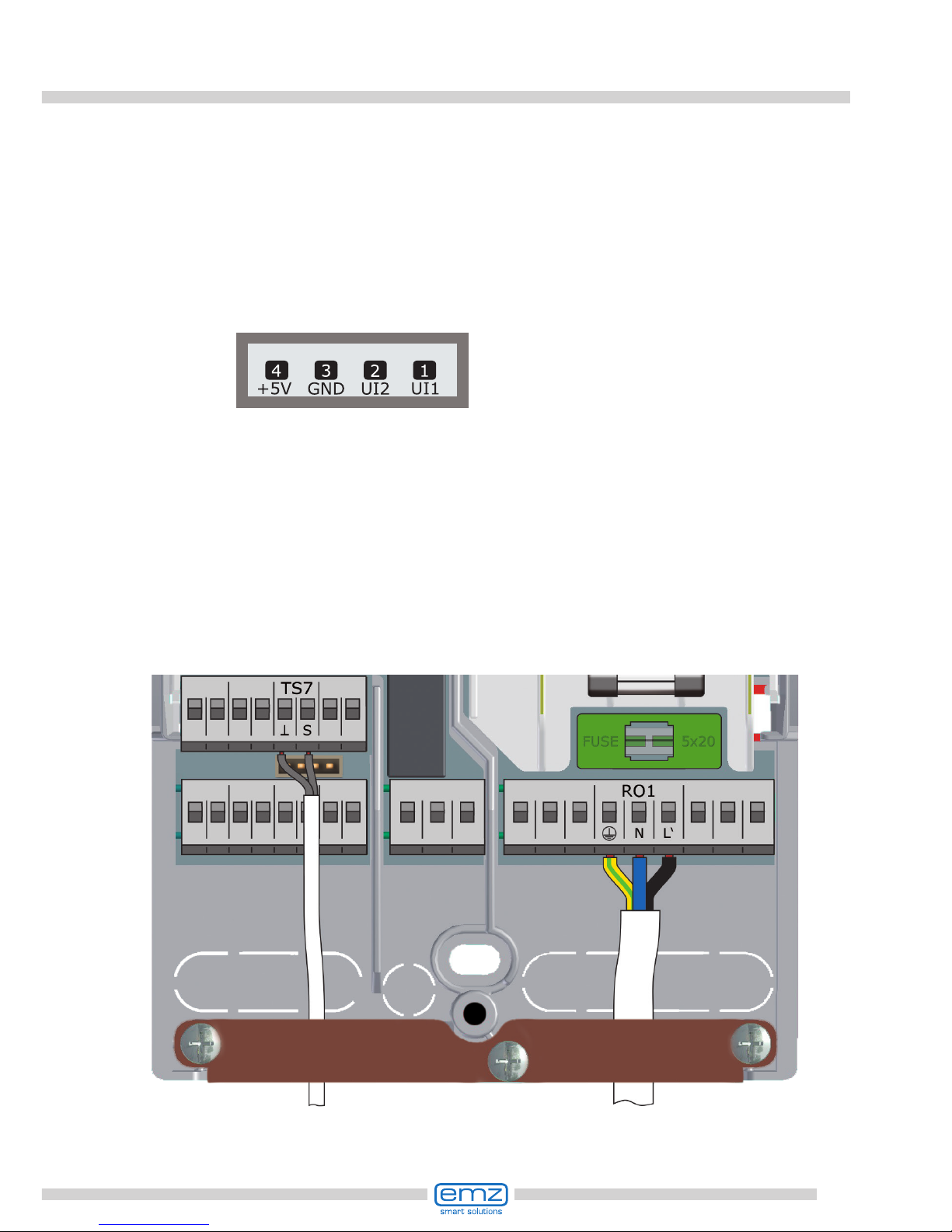
Pin assignment
b) Impeller sensor (incrementation input)
An impeller sensor can be connected to TS6 and must be adjusted during
installation. The temperature sensor for the solar return line must be set
in the menu ›1.1.4 Heat quantities‹.
All plant layouts permit solar radiation measurement using an impeller sensor.
Connection to power supply
High-efciency pump:
A high-efciency pump can be connected via RO1 or RO2.
The appropriate control signal is issued at TS7 / TS8 / (TS4).
Thus, TS4 is no longer available as input.
The control signal may be an analog voltage 0 - 10V or a PWM signal.
For further details, please refer to the pump specication.
For denition and settings, the professional mode under 1.2.9 has been provided.
RO1 or RO2:
230V supply of the
high-efciency pump
TS7 / TS8 / (TS4):
PWM-control signal for
the high-efciency pump
Left-hand terminal:
GND
Right-hand terminal:
Signal
18
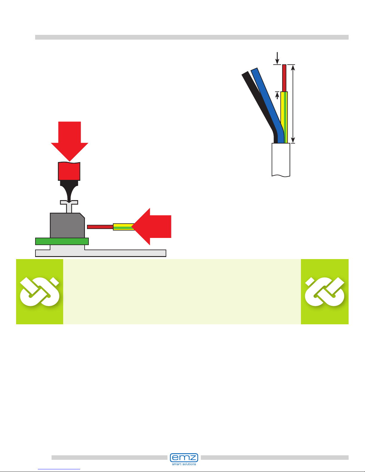
Connection to power supply
For connection, press the actuation pushbutton
of the spring-type terminal using a screwdriver and
insert the wire to its stop in the appropriate port.
Release the actuation pushbutton and
pull the cable slightly to ensure that it
is safely clamped.
Important!
Before closing the terminal cover, make
sure the strain relief device is tightened safely.
Check once more that all cables are in good
condition and connected correctly.
The strain relief device can only ensure solid
clamping if the cables are not stripped to a length
of over 35 mm.
Insulation of the individual wires must be
removed over a length of 9 - 10 mm to ensure
safe electric contact in the spring-type terminal.
Stranded wires must be provided with cable end sleeves!
9-10 mm
max.
35 mm
19
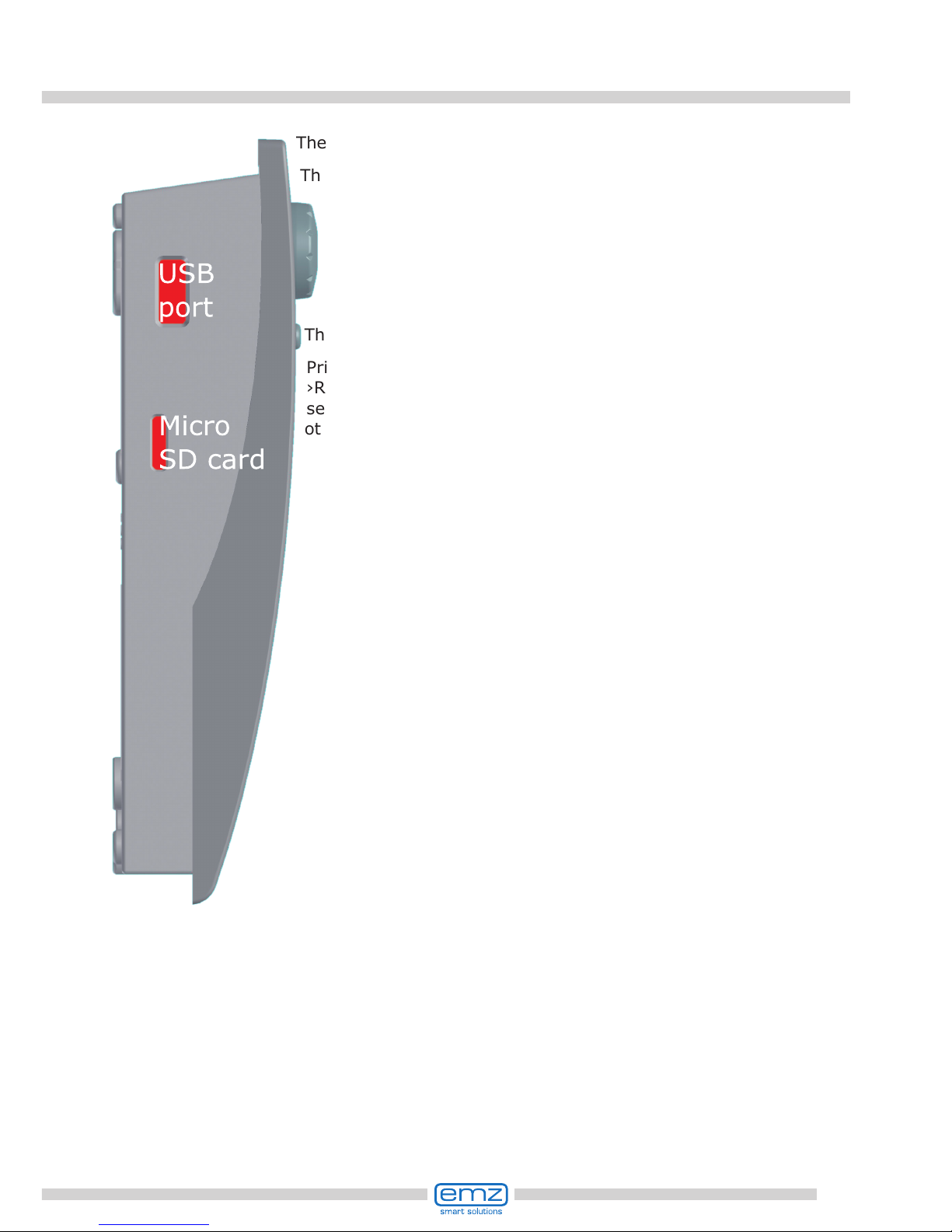
Data interfaces
The solar controller has the following data interfaces:
The cut-outs at the left of the housing base accommodate a USB
port as well as a slot for a storage medium (Micro SD card).
These interfaces are used, for example, for reading of error
messages or log data or loading of software updates.
The USB port provides access to the Micro SD card.
Only SD cards approved by emz must be used.
The controller automatically detects the Micro SD card.
Prior to removing the Micro SD card
›Rem.SD card safely‹ must be
selected in ›1.2 Settings‹,
otherwise data loss may occur.

20
Hydraulic systems
Boiler with disable
recharge feature,
efciency optimization
Boiler with disable
recharge feature
time-/temperaturecontrolled, in combination
Boiler, e. g. using fossil
fuels/ solid fuels/
heat pump etc.
Hydraulic
heat exchanger
Temperature probes
Switching valve
Solar collector panel
Secondary yield
Solar collector panel
Main yield
Swimming pool
Warmwasserspeicher/
Pufferspeicher mit
Wärmetauschern
Warm water /
buffer tank without
heat exchanger
Heating pump
Return line
Supply line
Note!
Dene structure and design of the plant already when planning
the entire solar thermal system and align the design with the
one of the hydraulic systems of the controller!
If you want to complete an existing system or replace
the existing controller, please make sure that
smart Sol is compatible with the existing conguration!
The sensors are connected to TS1 to TS4, the order not being
signicant; pumps and valves are connected to RO1 / RO2 - The
interfaces are assigned to the functions in question on commissioning.

21
Hydraulic system 1
Connection to
power supply
Collector sensor 1
Solar circuit pump 1
Tank sensor 1, bottom
RO1
TS1
TS2
Tank 1
T1
Collector
sensor 1
Solar
circuit
pump 1
Tank
sensor 1,
bottom
22
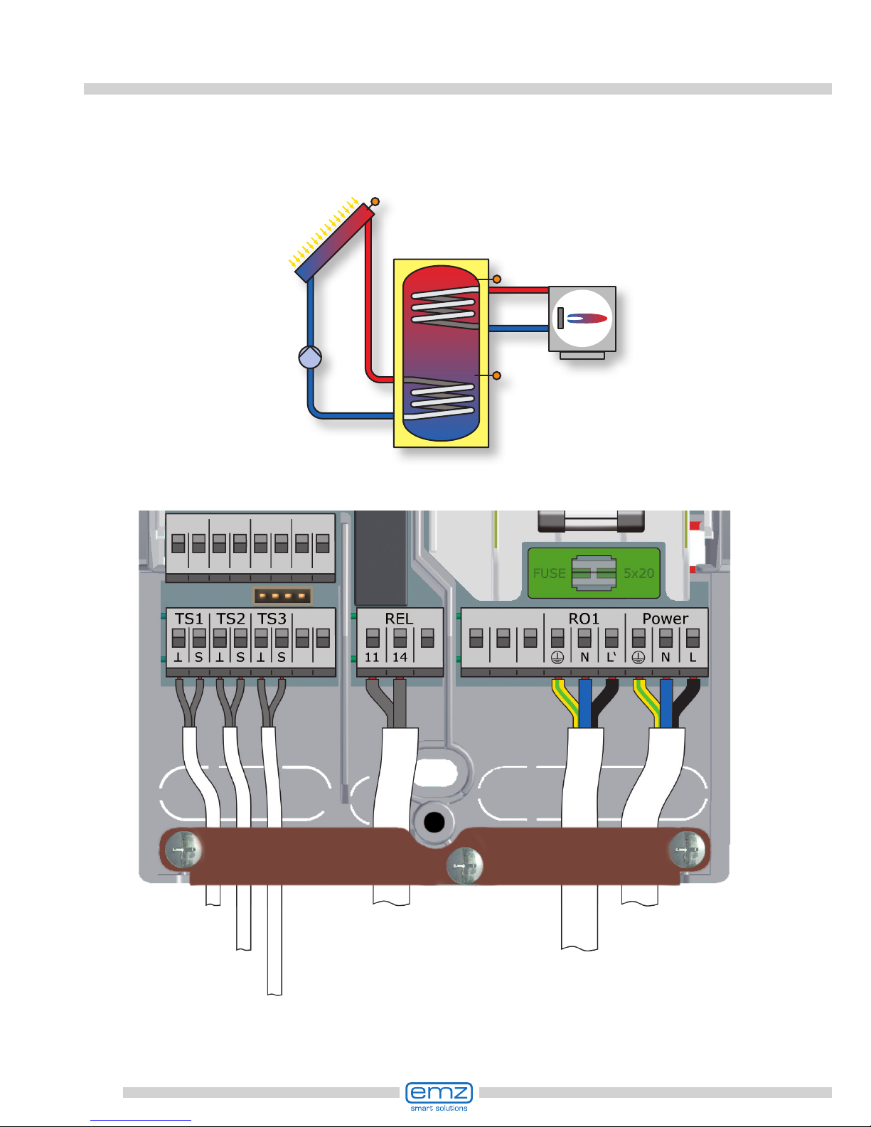
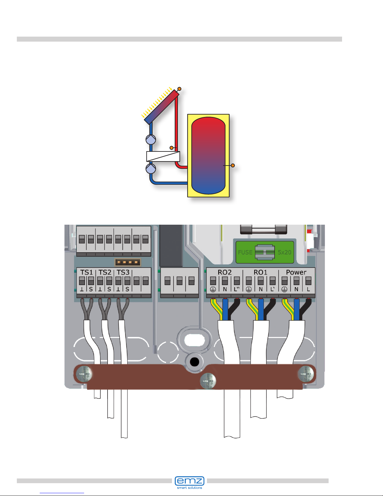
Hydraulic system 2
Tank sensor 1, top
Connection to
power supply
Collector sensor 1
Solar circuit pump 1
Tank sensor 1, bottom
RO1
TS1
TS2
TS3
Tank 1
T1
Collector
sensor 1
Solar
circuit
pump 1
Tank
sensor 1,
bottom
Tank sensor 1,
top
heating boiler connection according to
page 45-46
23
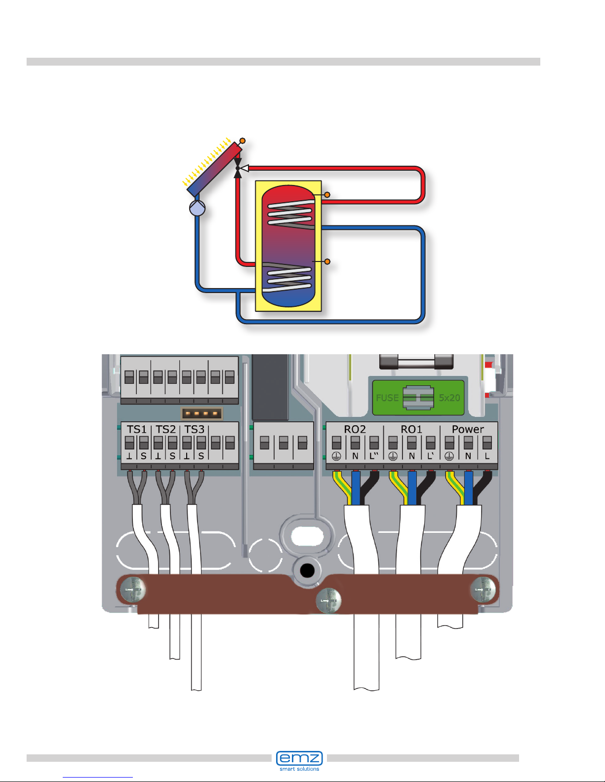
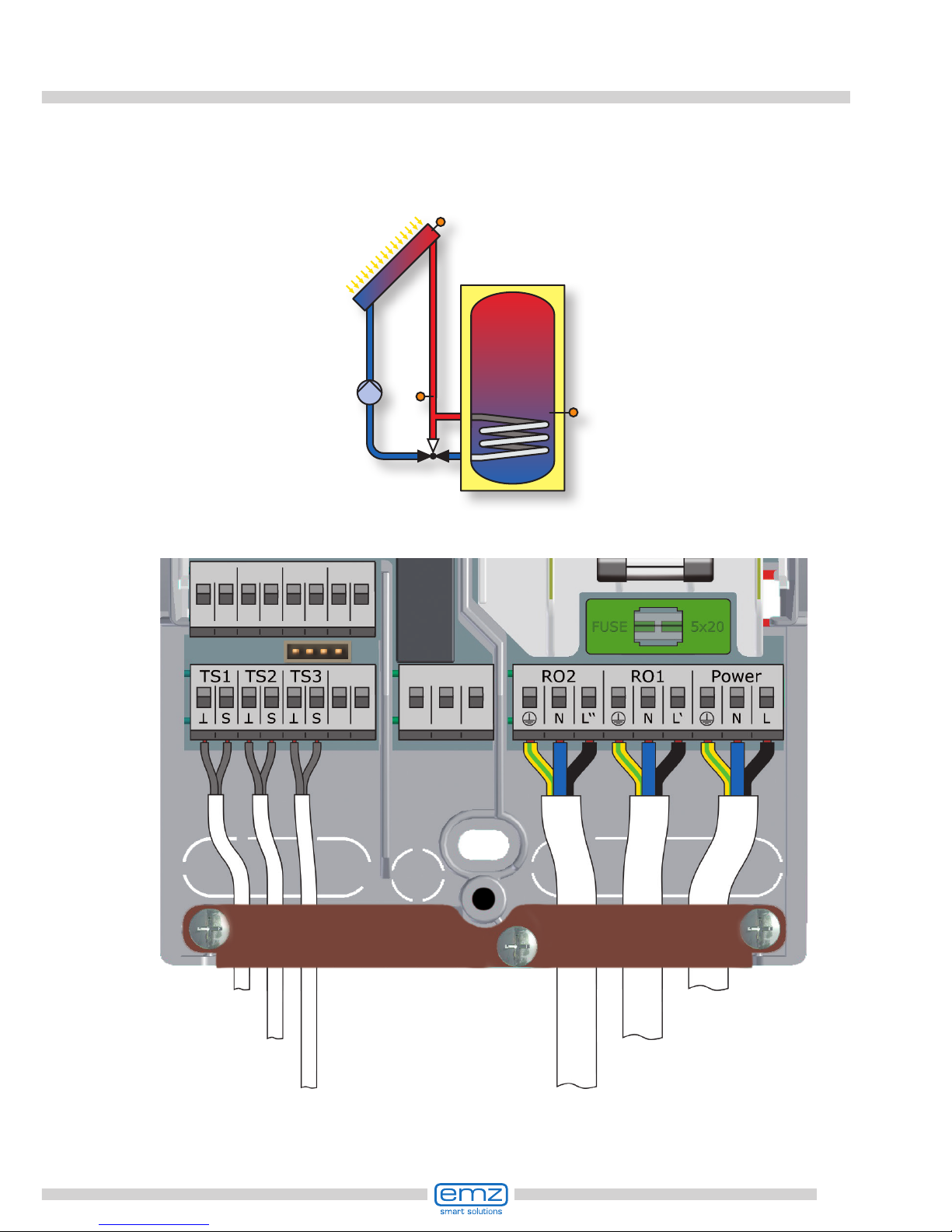
Hydraulic system 3
Tank sensor 1, top
Connection to
power supply
Collector sensor 1
Solar circuit pump 1
Tank sensor 1, bottom
Charging area valve
TS3
TS2
TS1
RO2
RO1
Tank 1
T1
Collector sensor 1
Solar
circuit
pump 1
Tank
sensor 1,
bottom
Tank sensor 1,
top
Charging area valve
24
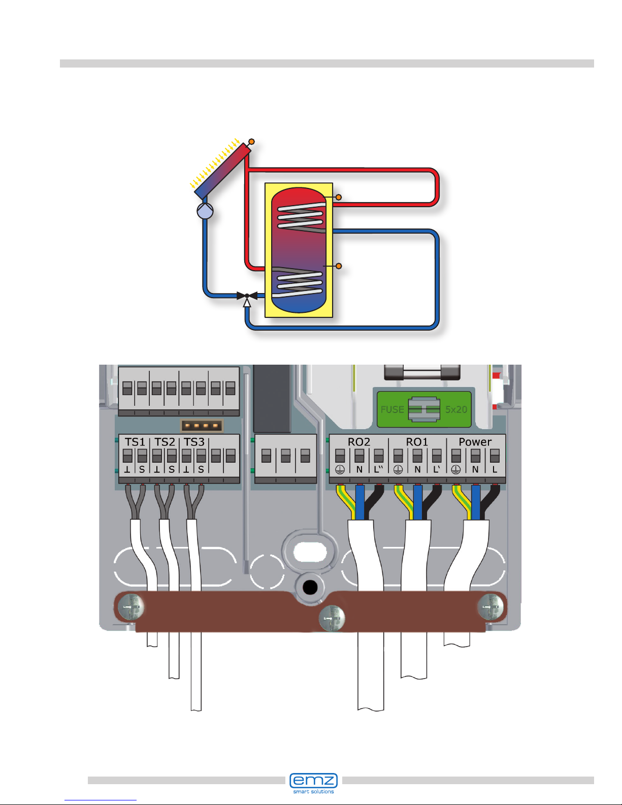
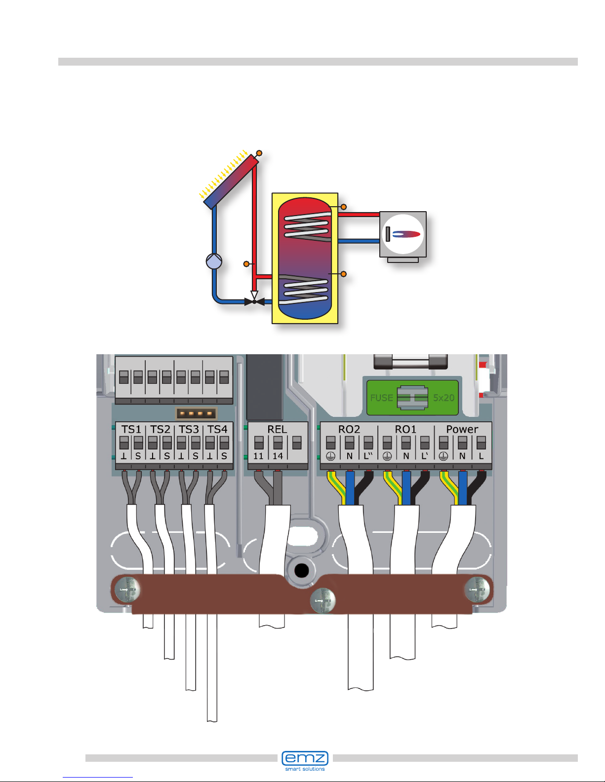
Hydraulic system 4
Tank sensor 1, top
Connection to
power supply
Collector sensor 1
Solar circuit pump 1
Tank sensor 1, bottom
Charging area valve
TS3
TS2
TS1
RO2
RO1
Tank 1
T1
Collector
sensor 1
Solar
circuit
pump 1
Tank
sensor 1,
bottom
Tank sensor 1,
top
Charg-
ing area
valve
25
Hydraulic system 5
Heat exchanger sensor
Connection to
power supply
Collector sensor 1
Solar circuit pump 1
Tank sensor 1, bottom
Heat exchanger pump
RO2
TS1
RO1
TS2
TS3
Tank 1
T1
Collector
sensor 1
Solar
circuit
pump 1
Tank
sensor 1,
bottom
Heat ex-
changer
sensor
Heat
exchanger
pump
26
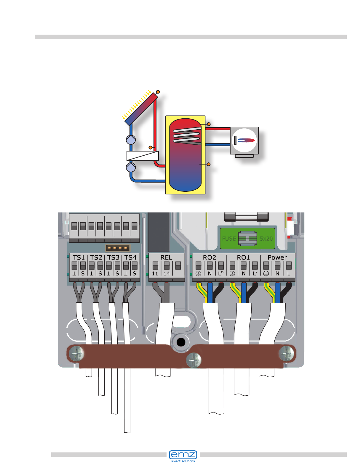
Hydraulic system 6
Tank sensor 1, top
Connection to
power supply
Collector sensor 1
Solar circuit pump 1
Tank sensor 1, bottom
Heat exchanger pump
Heat exchanger sensor
RO2
TS1
RO1
TS2
TS4
Tank 1
T1
Collector
sensor 1
Solar
circuit
pump 1
Tank
sensor 1,
bottom
Heat ex-
changer
sensor
Heat
exchanger
pump
TS3
Tank sensor 1,
top
Heating boiler
connection according
to page 45-46
27
Hydraulic system 7
Bypass sensor
Connection to
power supply
Collector sensor 1
Solar circuit pump 1
Tank sensor 1, bottom
Bypass valve
RO1
TS1
TS3
RO2
TS2
Tank 1
T1
Collector
sensor 1
Solar
circuit
pump 1
Tank
sensor 1,
bottom
Bypass valve
Bypass
sensor
28
Hydraulic system 8
Tank sensor 1, top
Connection to
power supply
Collector sensor 1
Solar circuit pump 1
Tank sensor 1, bottom
Bypass valve
Bypass sensor
Heating boiler
connection according
to page 45-46
RO1
TS1
TS4
RO2
TS2
Tank 1
T1
Collector
sensor 1
Solar
circuit
pump 1
Tank
sensor 1,
bottom
Bypass valve
Bypass
sensor
TS3
Tank sensor 1,
top
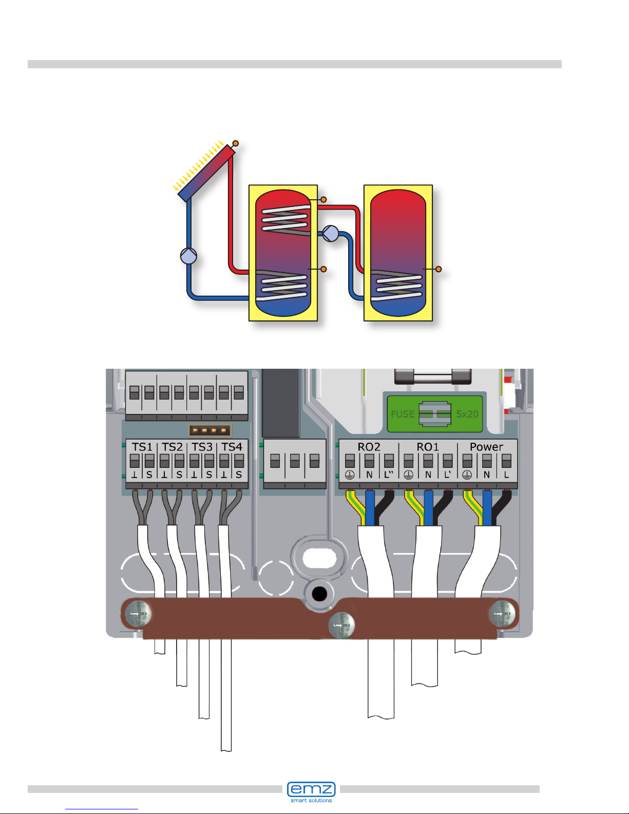
29
Hydraulic system 9
Transfer pump
Tank sensor 2, bottom
Tank sensor 1, top
Connection to
power supply
Collector sensor 1
Solar circuit pump 1
Tank sensor 1, bottom
TS4
RO1
TS1
TS3
TS2
RO2
Tank 1
T1
Tank 2
T2
Collector
sensor 1
Solar
circuit
pump 1
Tank
sensor 1,
bottom
Transfer
pump
Tank sensor 1,
top
Tank
sensor 2,
bottom
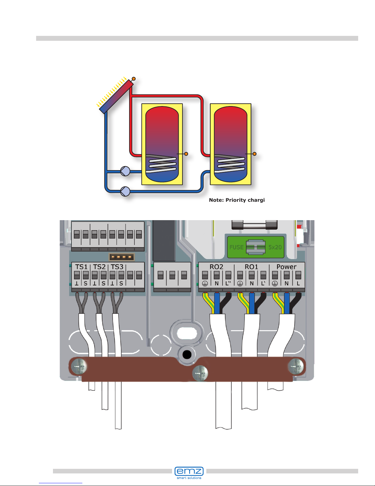
30
Hydraulic system 10
Note: Priority charging has
been set to T2 in the factory.
Tank sensor 2, bottom Solar circuit pump 2
Connection to
power supply
Collector sensor 1
Solar circuit pump 1
Tank sensor 1, bottom
TS2
TS1
TS3
RO1
RO2
Tank 1
T1
Tank 2
T2
Collector
sensor 1
Solar
circuit
pump 1
Tank
sensor 1,
bottom
Tank
sensor 2,
bottom
Solar circuit pump 2
 Loading...