

HEATING SYSTEM CONTROLLER FOR HEAT
GENERATION AND DISTRIBUTION
OPERATING AND INSTALLATION
INSTRUCTIONS
emz - THE SMILING COMPANY

These Operating and Installation Instructions are an integral part of the product.
› Read Assembly and Operating Instructions carefully before using the product.
› Keep them in a safe place during the product's entire service life.
Translated from the German original version ©emz 2018 - Subject to modifications.
The contents and representations of these Operating and Installation Instructions are the intellectual
property of emz-Hanauer GmbH & Co.KGaA.
Unauthorized disclosure, reproduction, distribution or editing of this documentation as well as
exploitation, utilization or publication, are prohibited.
The rights to the word and design marks ›emz - smart solutions‹ and ›smart Econ‹ are the exclusive
property of emz-Hanauer GmbH & Co.KGaA.
The rights to any cited brands, names or logos are the property of the respective developers/
licensees.

TABLE OF CONTENTS
Table of contents
Table of contents................................................................................................................................ 3
Important information ......................................................................................................................... 8
Notes on this manual ....................................................................................................................8
Safety information ......................................................................................................................... 8
Conditions of use ..........................................................................................................................9
Intended use ...............................................................................................................................10
Installation and connection ......................................................................................................... 10
Product description .......................................................................................................................... 11
Outdoor temperature-controlled room heating............................................................................ 11
Self-adjustment / heating behavior ............................................................................................. 11
Control of heat generators ..........................................................................................................11
smart EconControl options..........................................................................................................12
Water heating.............................................................................................................................. 12
Anti-legionella function................................................................................................................ 12
Solar heating system .................................................................................................................. 12
smart Econ Transmission technology ......................................................................................... 12
Distance communication via the Internet .................................................................................... 12
Remote maintenance via smart Econ Cloud............................................................................... 12
Cloud access ......................................................................................................................... 13
Information and control .......................................................................................................... 13
Safety..................................................................................................................................... 13
Data protection....................................................................................................................... 13
Device description............................................................................................................................ 14
smart Econ HCW ........................................................................................................................14
smart Econ HCW 1620 Expansion module................................................................................. 14
Connections and interfaces on the smart Econ HCW............................................................ 15
smart Econ Room controller .......................................................................................................15
CAN bus line ............................................................................................................................... 15
Operating the smart Econ room controller ....................................................................................... 16
Heating........................................................................................................................................ 16
Special functions......................................................................................................................... 16
Operating the smart Econ Userinterface.......................................................................................... 17
Control elements......................................................................................................................... 17
Display ........................................................................................................................................17
Prompts during operation................................................................................................................. 18
Overview mode ........................................................................................................................... 18
Menu ........................................................................................................................................... 18
Select menu items ...................................................................................................................... 19
Overview menu ........................................................................................................................... 19
smart Econ - emz-HCW - 180116 3

TABLE OF CONTENTS
›Heat Circuits‹ menu (Overview menu)....................................................................................... 20
›Temperatures‹ menu .................................................................................................................21
›Outputs‹ menu ...........................................................................................................................21
›Diagnosis‹ menu ........................................................................................................................22
Error messages........................................................................................................................... 22
Information ..................................................................................................................................22
Settings during operation .................................................................................................................23
Entering the access code............................................................................................................23
Change values ............................................................................................................................23
Menu structure ............................................................................................................................24
Abbreviations in the menus.........................................................................................................25
Main menu ..................................................................................................................................26
›OPERATING MODES‹ menu ....................................................................................................27
Operating mode ›AUTOMATIC‹.............................................................................................28
Operating mode ›DAY‹...........................................................................................................28
Operating mode ›NIGHT‹.......................................................................................................28
Operating mode ›FROST PROTECTION‹ ............................................................................. 28
Operating mode ›SUMMER‹ .................................................................................................. 28
Operating mode ›FLOOR PAVEMENT HEATING‹................................................................28
Operating mode ›OFF‹...........................................................................................................29
Operating mode ›CHIMNEY SWEEP‹ ...................................................................................29
›TIMER PROGRAMS‹ menu....................................................................................................... 30
Setting heating periods and temperatures ............................................................................. 31
Selecting the day of the week ................................................................................................31
Setting times and temperatures ............................................................................................. 31
›COPY DAY...‹ .......................................................................................................................31
›COPY ALL VALUES...‹ ......................................................................................................... 31
Table for rooms and heating times......................................................................................... 33
Table for rooms and heating times......................................................................................... 34
›HOLIDAY PERIODS‹ menu....................................................................................................... 35
›HEAT CIRCUITS‹ menu ............................................................................................................36
›DOMESTIC HOT WATER‹ menu .............................................................................................. 38
Setting the domestic hot water setpoint temperature.............................................................38
Setting the domestic hot water heating times ........................................................................39
Manual control of domestic hot water heating........................................................................ 40
Setting circulation times .........................................................................................................40
Configure circulation temperatures ........................................................................................41
›GENERAL‹ menu....................................................................................................................... 42
Setting the language of the menu .......................................................................................... 42
Set date and time................................................................................................................... 42
Adjusting the display brightness and buzzer volume ............................................................. 43
›INTERNET‹ menu......................................................................................................................44
4 smart Econ - emz-HCW - 180116

TABLE OF CONTENTS
Installation and connection............................................................................................................... 45
smart Econ Temperature sensor ................................................................................................ 46
smart Econ HCW ........................................................................................................................47
Dimensions smart Econ HCW ............................................................................................... 47
Opening the smart Econ HCW housing ................................................................................. 48
Installation location smart Econ HCW.................................................................................... 48
Installation smart Econ HCW ................................................................................................. 49
Connection smart Econ HCW ................................................................................................ 50
smart Econ Room controller .......................................................................................................51
Node number room controller ................................................................................................51
Dimensions room controller ................................................................................................... 51
Opening the room controller housing..................................................................................... 51
Installation location room controller ....................................................................................... 51
Installation room controller..................................................................................................... 52
Room controller connection ................................................................................................... 52
Connection CAN-Bus.................................................................................................................. 53
Cable routing............................................................................................................................... 53
4-pole CAN bus line ............................................................................................................... 54
Internet-based network .................................................................................................................... 55
Prerequisites ............................................................................................................................... 55
Hydraulic systems and connection diagrams................................................................................... 56
Further hydraulic systems........................................................................................................... 56
Hydraulic symbols....................................................................................................................... 57
Hydraulic system 1: ›HCW 001 Sol‹ (HCW 810) ........................................................................ 58
Hydraulic system 2: ›HCW 002 SF‹ (HCW 810) ......................................................................... 60
Hydraulic system 3: ›HCW 003‹ (HCW 810)............................................................................... 62
Hydraulic system 4: ›HCW 004 Sol‹ (HCW 810) ........................................................................ 64
Hydraulic system 5: ›HCW 005 Sol‹ (HCW 810) ........................................................................ 66
Hydraulic system 6: ›HCW 006 HP‹ (HCW 810)......................................................................... 68
Hydraulic system 7: ›HCW 007 Sol-SF‹ (HCW 810)................................................................... 70
Hydraulic system 8: ›HCW 008 Sol‹ (HCW 1620 Base Unit)...................................................... 72
Hydraulic system 8: ›HCW 008 Sol‹ (HCW 1620 Expansion Module)........................................ 74
Hydraulic system 9: ›HCW 009 SF‹ (HCW 1620 Base Unit) ...................................................... 76
Hydraulic system 9: ›HCW 009 SF‹ (HCW 1620 Expansion Module) ........................................ 78
Hydraulic system 10: ›HCW 008 Sol‹ (HCW 1620 Base Unit).................................................... 80
Hydraulic system 10: ›HCW 008 Sol‹ (HCW 1620 Expansion Module)...................................... 82
Hydraulic system 11: ›HCW 011 KAS‹ (HCW 1620 Base Unit) .................................................. 84
Hydraulic system 11: ›HCW 011 KAS‹ (HCW 1620 Expansion Module).................................... 86
Hydraulic system 12: ›HCW 012 Sol‹ (HCW 1620 Base Unit).................................................... 88
Hydraulic system 12: ›HCW 012 Sol‹ (HCW 1620 Expansion Module)...................................... 90
Hydraulic system 13: ›HCW 013 HP‹ (HCW 1620 Base Unit) .................................................... 92
Hydraulic system 13: ›HCW 013 HP‹ (HCW 1620 Expansion Module) ...................................... 94
smart Econ - emz-HCW - 180116 5

TABLE OF CONTENTS
Hydraulic system 14: ›HCW 014 Sol-SF‹ (HCW 1620 Base Unit) ..............................................96
Hydraulic system 14: ›HCW 014 Sol-SF‹ (HCW 1620 Expansion Module) ................................98
Abbreviations for hydraulic components, inputs and outputs .................................................... 100
Function description .......................................................................................................................101
Solar operation..........................................................................................................................101
Collector cooling................................................................................................................... 101
Storage recooling................................................................................................................. 101
Limit temperature .................................................................................................................101
Solar pump anti-lock circuit (ABS) ............................................................................................101
Buffer management function .....................................................................................................101
Heat generator ..........................................................................................................................102
Modulating heat generators (optional) .................................................................................102
Operation of two heat generators......................................................................................... 102
Air-source heat pump and peak load boiler .........................................................................102
Wood-fired boiler and conventional heat generator .............................................................102
Timer program........................................................................................................................... 103
Global day/night temperature....................................................................................................103
Frost protection .........................................................................................................................103
Summer operation..................................................................................................................... 103
Domestic hot water temperature ...............................................................................................103
Domestic hot water priority........................................................................................................ 104
Outdoor temperature-controlled setting .................................................................................... 104
Control loops with mixers ..................................................................................................... 104
Heating curve....................................................................................................................... 104
Using the smart Econ room controller..................................................................................105
Outdoor temperature-guided control without remote setting................................................105
Outdoor temperature-guided control with remote setting.....................................................105
Outdoor temperature-guided control with room influence .................................................... 106
Commissioning...............................................................................................................................107
Device configuration.......................................................................................................................108
Enter access code for the installer ............................................................................................108
Main menu for the installer........................................................................................................ 108
›INSTALLER‹ menu ..................................................................................................................109
›COMMISSIONING‹ menu........................................................................................................ 110
Select hydraulic system .......................................................................................................111
Setting the date, time and daylight saving time.................................................................... 111
Configuring heating circuits/zones .......................................................................................111
Change heating curve .......................................................................................................... 113
Configure request for heat generator ................................................................................... 114
Configure heat pump............................................................................................................ 115
Configure solid fuel boiler..................................................................................................... 116
6 smart Econ - emz-HCW - 180116

TABLE OF CONTENTS
Configure solar system ........................................................................................................ 117
Sensor adjustment ............................................................................................................... 121
Configuring frost protection.................................................................................................. 123
Configuring the room controller ›CONFIG RC‹ .................................................................... 123
›OPERATING HOURS‹ Menu .................................................................................................. 125
›TEST‹ Menu ............................................................................................................................ 126
Test operation...................................................................................................................... 126
Manual switching of outputs................................................................................................. 127
Simulate temperatures......................................................................................................... 127
Simulate room temperatures................................................................................................ 128
Simulate inputs .................................................................................................................... 128
Bus setup............................................................................................................................. 129
›HEAT CIRCUITS‹ menu (Installer) .......................................................................................... 130
Configure heating circuit ...................................................................................................... 131
Configuring room temperature influence on the heating curve
(heating circuits without mixer) ............................................................................................ 132
Configuring the mixer control (heating circuits with mixer) .................................................. 133
Configuring the heating pump.............................................................................................. 134
›DOMESTIC HOT WATER‹ menu (Installer) ............................................................................ 135
Setting the domestic hot water setpoint temperature (Installer)........................................... 136
Configure domestic hot water priority .................................................................................. 137
Configuring the domestic hot water pump ........................................................................... 137
Setting circulation times (Installer) ....................................................................................... 138
Configuring the circulation pump ......................................................................................... 138
Configure circulation temperatures ...................................................................................... 139
›GENERAL‹ menu (Installer) .................................................................................................... 140
›INTERNET‹ menu (Installer).................................................................................................... 143
smart Econ Cloud setup....................................................................................................... 143
Generate new Auth-Code .................................................................................................... 144
Delete user........................................................................................................................... 144
Technical data................................................................................................................................ 145
smart Econ HCW ......................................................................................................................145
smart Econ Room controller ..................................................................................................... 145
smart Econ Temperature sensor .............................................................................................. 145
Solar and boiler temperature sensors.................................................................................. 145
Storage tank and buffer temperature sensor .......................................................................145
Flow/return contact temperature sensor .............................................................................. 146
Characteristic curve and resistance values of PT1000 temperature sensors...................... 146
Disassembly/disposal..................................................................................................................... 147
Warranty and liability...................................................................................................................... 148
Index .............................................................................................................................................. 149
smart Econ - emz-HCW - 180116 7
IMPORTANT INFORMATION
Important information
Notes on this manual
These operating and installation instructions are intended for both system operators and specialist
installers.
The instructions are divided into several sections for a better overview.Each of these sections is
marked with an icon at the edge of each page:
This symbol indicates Sections with general information.
These sections contain important information, safety instructions and descriptions of the
properties of the controller as well as general operating instructions.
These sections are intended for both operators and professional installers.
This symbol indicates sections with information on regular operation.
These sections contain descriptions of how to input individual settings on the controller.
These sections are aimed in particular at system operators.
This symbol indicates sections with information for installation, commissioning, sys-
tem-specific programming and further specialist information for specialist installers.This
information enables specialist installers to set the controller for the proper operation of the
system.
NOTE
Safety information
The assembly and operating instructions indicate possible hazards:
All depictions mentioned are examples and serve for a better
understanding.Content and sequence depend on the selected
system.
Errors and modifications reserved.
DANGER indicates an almost certain danger of serious personal injury or death.
WARNING indicates a possible danger of serious personal injury.
CAUTION indicates a possible danger of slight personal injury.
NOTICE indicates a possible danger of damage to the equipment.
8 smart Econ - emz-HCW - 180116

IMPORTANT INFORMATION
When handling the smart Econ heating system controller and accompanying equipment, please
make sure that the safety provisions in the assembly and operating instructions are complied with!
Conditions of use
These instructions describe the installation, startup, operation, repair and disassembly of the
smart Econ heating system controller.
Observe all technical documentation of all the components used such as boiler, tank, pumps, mixers, and valves, etc. when operating the system.
DANGER
Assembly, connection, startup, repair and disassembly
Danger of death by electrocution!
Whenever working with the terminal cover open, make sure
that all poles of the power supply are completely disconnected
and protected against being switched on again!
The heating system controller is used by the system operator, who in most cases will be a layperson.
NOTE
Make sure not to use the heating system controller until you have thoroughly read and understood
these Assembly and Operating Instructions and the safety provisions.Comply with all safety provisions and contact a specialist in case of doubt.
NOTE
Keep these assembly and operating instructions and all reference documents accessible at all
times.
When relocating or when selling the device, hand the documents over to your successor.
NOTE
The heating system controller replaces by no means the safety
components required under system engineering aspects!
The installer of the heating system controller must instruct the
system operator on the handling, function and principle of
operation of the smart Econ and the components connected to
it!
Only adults with the appropriate knowledge and experience
may access the device during operation./when it is in operation.
smart Econ - emz-HCW - 180116 9
IMPORTANT INFORMATION
NOTE
Intended use
The smart Econ heating system controller may only be used as a controller for thermal systems.
Always observe all described specifications during operation!/when operating the device!
Only specialists may install and set up the heating system controller.
The installer must have read and understood the operating manual.The installer explains all the relevant functions to the operator.
For operation, it is essential that the housing is closed and undamaged.
Installation and connection
Before connecting to the electrical system, the smart Econ HCW Userinterface and the expansion
module must be fixed to a vertical, robust surface (wall), see “Installation and connection” on
page 45.
For its own power supply and that of the outputs, connect the heating system controller to an electrical energy supply system in accordance with the technical data.
Make sure that only a dry or slightly moistened cloth is used for
cleaning and servicing of the housing, the control elements
and the display.
The surfaces must never get into contact with cleaning products or solvents - mat, brittle or slightly dissolved plastic parts
must be replaced immediately!
A device with damaged housing must not be operated!
DANGER
Loose installation or connection
Danger of death by electrocution!
Whenever working with the terminal cover open, make sure
that all poles of the power supply are completely disconnected
and protected against being switched on again!
NOTE
The heating system controller may only be assembled, connected, commissioned, repaired and disassembled by specialists.
The installation and protection regulations for the installation,
commissioning and operation of low-voltage installations in
accordance with EU and national law must be observed.
10 smart Econ - emz-HCW - 180116

PRODUCT DESCRIPTION
Product description
The smart Econ heating system controller was especially developed for single-family houses and
apartment buildings.The goals are the creation of optimum comfort for residents and the greatest
possible ease of use for the system operator.
The smart Econ heating system controller can be operated either via the 4 buttons and the rotary/
push button on the control panel or optionally via existing internet access using a PC, smartphone or
tablet.
The smart Econ heating system controller is a modern system to control the entire domestic technology of single-family houses and apartment buildings.
As many components of domestic technology can be integrated into one single system, there are
many options for system optimization (e.g. energy efficiency, ease of operation, optimization of comfort and maximum coziness).
Outdoor temperature-controlled room heating
When delivered, the controller is designed for purely outdoor temperature-controlled systems.
Depending on the outside temperature, control valves regulate the flow temperature of the respective control circuit according to the set heating curve.
A smart Econ room controller can also be used for remote adjustment.The room temperature influence can be set as an additional reference variable by connecting the room controller.
To take solar radiation into account, several room controllers can be attached (e.g. to separate the
heating circuits on the north and south side).
Self-adjustment / heating behavior
Optionally, heating behavior can be influenced by using a smart Econ room controller.
The inertia of the room is initially assumed to be "average" and later adapted in a learning phase of
about 3 days, during which the desired progression of the room temperature is compared with the
actual development in the main room.In most cases, the optimum setting is found after 3 days.Of
course, this adjustment can be repeated at any time.
This way, heating operation is optimized in terms of comfort, homeliness and energy consumption
independently of the type of heating (underfloor heating system, wall heating or any combination
thereof).
Control of heat generators
In general, all types of heat generators (gas, oil, solid fuel, district heating, heat pumps, ...) can be
integrated into the smart Econ system control.
The heat generators are either enabled by a smart Econ room controller when heat is required or
controlled according to the heat demand flexibly depending on outdoor temperature or constantly
based on tank temperature etc.
The objective of this is to achieve the longest possible switching intervals to minimize the exhaust
emissions by reducing the number of startups and at the same time to increase the heat generator's
service life.
smart Econ - emz-HCW - 180116 11

PRODUCT DESCRIPTION
smart EconControl options
If a room controller is used, the flow temperature of the associated heating circuit can be raised
briefly for rapid heating if there is a large deviation in the room temperature.The flow temperature is
reduced during setback operation.
If there is no heat demand, the pumps of the relevant heating circuits are switched off.
Water heating
Different preset temperatures can be defined for different times of the day.This allows for energy
savings in general, as the hot water is only controlled to the required temperature in the desired time
range.
Depending on the hydraulic system, two temperature sensors (top and bottom) can be defined (e.g.
switch on when the storage tank becomes "cold" at the top, and switch off when the lower part is
"warm").
A boiler priority circuit is also supported.
Anti-legionella function
To kill germs, the thermal disinfection program is carried out once a week every Monday.The
domestic hot water is heated to 63°C.
Solar heating system
A configurable differential temperature control ensures that the solar heating system generates as
much heat as possible.
You can load several heat consumers (buffer, boiler, swimming pool, etc.) with different temperature
levels.
smart Econ Transmission technology
The components of the heating system smart Econ controller can be networked together.This way,
data is transferred via the fieldbus system CAN (Control Area Network).
“CAN bus line” on page 15
Distance communication via the Internet
The smart Econ heating system controller features an integrated Ethernet interface. that can be
used to connect it to the Internet.The Ethernet makes remote switching possible.The user can also
download the configuration, operating statuses, archive and software updates from the network.The
information messages can be sent directly via e-mail, free access to smart Econ Cloud provided.
“Internet-based network” on page 55
Remote maintenance via smart Econ Cloud
The smart Econ heating system controller can be remotely maintained via the smart Econ Cloud of
the company emz via the Internet. The current operating status of the system can be queried and
the configuration can be changed.
12 smart Econ - emz-HCW - 180116

PRODUCT DESCRIPTION
Cloud access
After one-time authentication using the TAN procedure (TAN key/ID code not included) and successful logon, the smart Econ Cloud provides remote access to the controller.Whether PC, Tablet or
Smartphone, the menu interface adapts automatically.
Access via: www.smarteconcloud.com
“smart Econ Cloud setup” on page 143
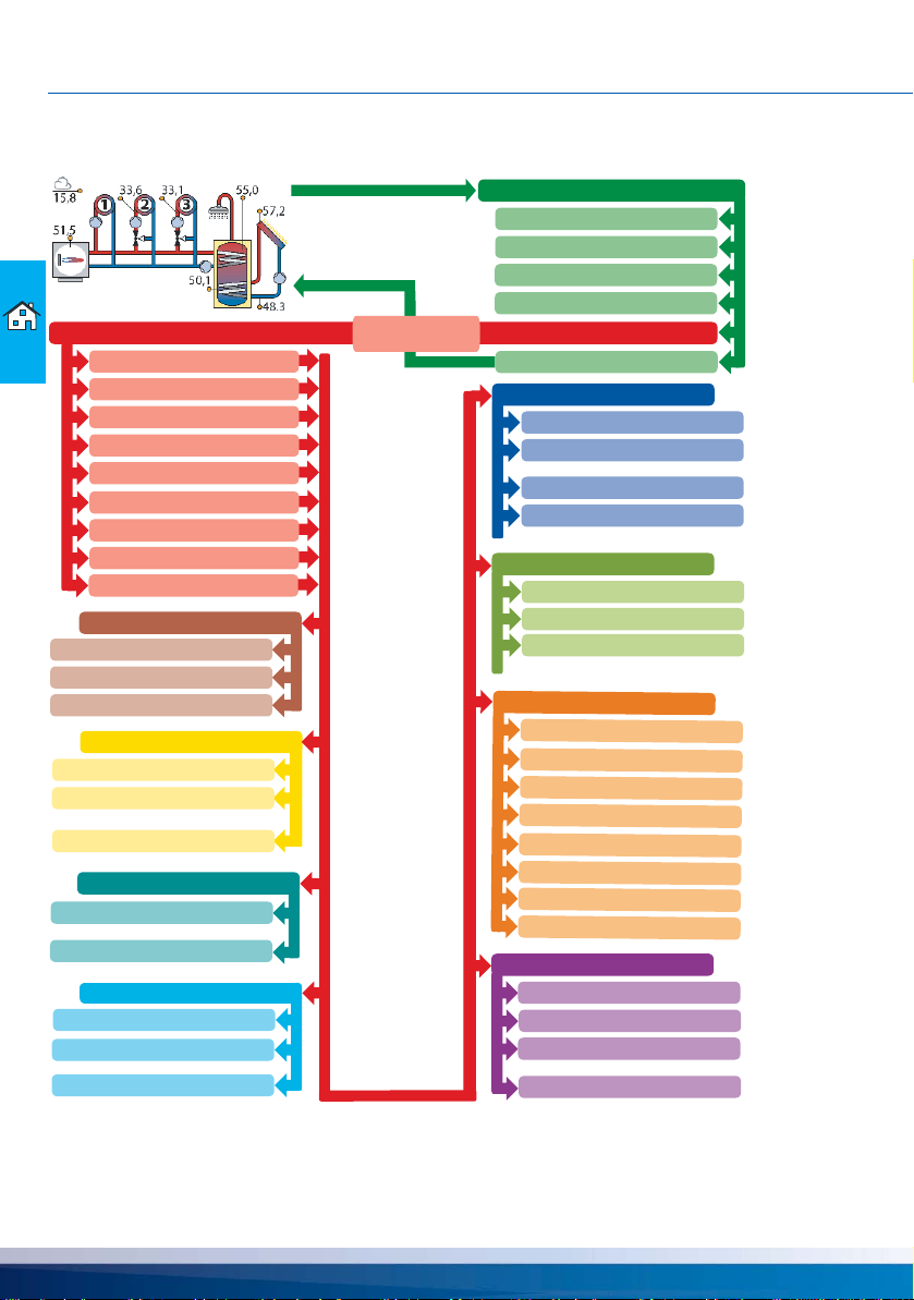
Information and control
The current status of the controlled pumps, valves and boiler can be read off at a glance from the
graphic system diagram.This is the graphic of the selected system that is also visible on the controller.
In addition to the current system data, the controller’s status messages, error messages and data
archive are available for viewing.In addition, the various operating modes can be selected and individual parameter values of the controller can be changed.
The recordings stored in the controller are processed graphically and can also be displayed together
over a longer period of time.
Safety
Access to the controller is protected in three ways.First, the ID code to be entered at the first login
and a randomly generated 20-digit authentication code - both codes will be checked internally at
each access later on.After logging in, the 6-or-more character, individual user password forms the
third level of protection.
Initial access is activated via a secure TAN procedure.
Data protection
The protection of personal data is our top priority.For identification purposes, no personal data other
than the name and a valid e-mail address is collected from the operator when registering.
smart Econ - emz-HCW - 180116 13
DEVICE DESCRIPTION
Device description
• smart Econ HCW - Heat Control Wall
Compact unit with Userinterface for wall mounting
- HCW 810 with 8 sensor inputs and 10 outputs
- HCW 1620 consisting of the base unit with Userinterface and an expansion module, networked
via CAN bus.Application for complex systems with 16 sensor inputs and 20 outputs
The devices are fitted with a micro-USB and an Ethernet connection at the factory.
Optional accessories:
• smart Econ RC - Room Control
Room unit for room temperature measurement and setpoint temperature adjustment
with party and setback function
• smart Econ Temperature sensor
Type and range depending on the design of the heating system
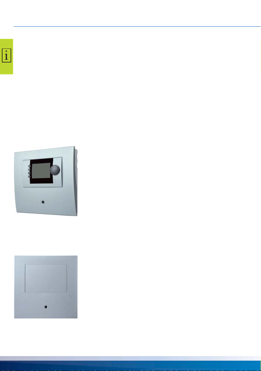
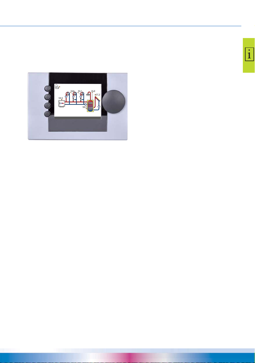
smart Econ HCW
smart Econ HCW integrates the controller and the Userinterface
into one compact housing for wall mounting.
Temperature sensors as well as pumps and valves are connected to the controller.
The smart Econ HCW is connected to the smart Econ Room
controllers via CAN bus.
The display shows the menus for configuration, the temperatures of all the configured temperature sensors, as well as diagnostics and error messages.
The Userinterface provides a combined turn/push button for
operating the menus as well as 4 function keys, see “Control
elements” on page 17.
smart Econ HCW 1620 Expansion module
smart Econ HCW 1620 is composed of the base unit with the
Userinterface and the expansion module.
Temperature sensors as well as pumps and valves are connected to the expansion module in the same way as to the base
unit.
The expansion module is connected to the base unit and the
smart Econ Room controllers via CAN bus.
14 smart Econ - emz-HCW - 180116

DEVICE DESCRIPTION
Connections and interfaces on the smart Econ HCW
The smart Econ HCW has the following connections inside the housing:
• Connections for pumps and mixers (terminal strips)
• Connections for temperature sensors (terminal strips)
• 1 CAN bus interface (terminal strip for 4-wire cable)
• 1 Ethernet interface (LAN) at the back of the housing (Western socket for CAT 5 cable)
An Internet connection can be established via the LAN interface. This allows additional PC operation via the smart Econ Cloud (access optional).
“Internet-based network” on page 55
• 1 USB interface inside the housing (Micro-USB-B)
“Installation and connection” on page 45
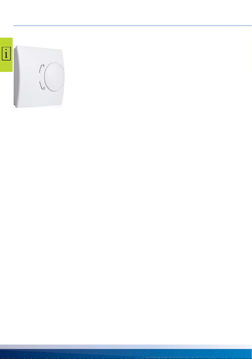
smart Econ Room controller
The smart Econ room controller determines the current room temperature.
The desired room temperature can be readjusted using the setting wheel.In
addition, the operating mode for the assigned heating circuits can be changed
via the end positions of the setting wheel:
In the end position (+) a permanent party mode (always heat)
and in the end position (-) a permanent setback function.
CAN bus line
Connect the individual system components in series with a 4-pole cable, the CAN bus line.
The CAN bus line merely has to be connected from one component to the next, which significantly
reduces the installation effort.
Data is transferred via the fieldbus system CAN (Control Area Network).
smart Econ - emz-HCW - 180116 15
OPERATING THE SMART ECON ROOM CONTROLLER
Operating the smart Econ room controller
Range +3 to -3 The room temperature setpoint is changed by the value set.
End position + Party function for the assigned heating circuits.The highest
room temperature setpoint entered is used, irrespective of the
time program.
End position - Setback function for the assigned heating circuits.The tem-
perature is controlled to the setback temperature entered for
this room.
Heating
• To readjust the desired room temperature, turn the setting wheel to the desired temperature difference.
Example:
The programmed room setpoint temperature is 21 °C.
The room controller is on 2.Step adjusted in direction + .
This results in a desired room temperature of 23 °C.
Special functions
• If you want to heat during the set-back times (party mode), turn the setting wheel to the end position +.
The connected heating circuit changes continuously to day mode until the setting wheel is reset.
• To activate the setback function (e.g. holiday), turn the setting wheel to the end position -.
The connected heating circuit changes to night mode until the setting wheel is reset.
16 smart Econ - emz-HCW - 180116
OPERATING THE SMART ECON USERINTERFACE
(1)
(2)
(3)
(4)
(5)
(6)
Operating the smart Econ Userinterface
Control elements
The smart Econ Userinterface is set up and operated with a combined turn/push knob (turn knob)
for menu navigation and 4 function buttons.
Basic display, overview mode
(1) Function key 1 / Abort (^)
(2) Select function key 2 / digit left (<)
Function keys 1 and 2 can be used for switching functions.
(3) Select function key 3 / digit right (>)
Function button for quick access and software switch
(4) Help function: INFO key for function explanations (i)
(If available, the operating options of the function keys are shown on the display.)
(5) Combined Turn/push button with OK button function for menu navigation
(6) Display
You input settings and queries using the turn/push button:
“Select menu items” on page 19
“Change values” on page 23
Display
The smart Econ Userinterface has a graphic display which is permanently illuminated to indicate the
operating status and to communicate in case of setup, malfunction, change and evaluation.
If no action is taken on the control elements of the Userinterfacefor a longer period (approx. 5 min),
the menu switches back to the hydraulic system and the brightness of the display is dimmed
(“Adjusting the display brightness and buzzer volume” on page 43).
To access the main menu, the access code must be entered (again).
smart Econ - emz-HCW - 180116 17
PROMPTS DURING OPERATION
04.04.18 10:35:10 Server: online AUTOMATIC
Hea t Cir c u its
Temperatures
Outputs
Diagnostics
MENU
BACK
26.02.2018 14:23:03 Server: online AUTOMATIC
Prompts during operation
Using the smart Econ Userinterface, you can check the current system status and adjust the settings.
NOTE
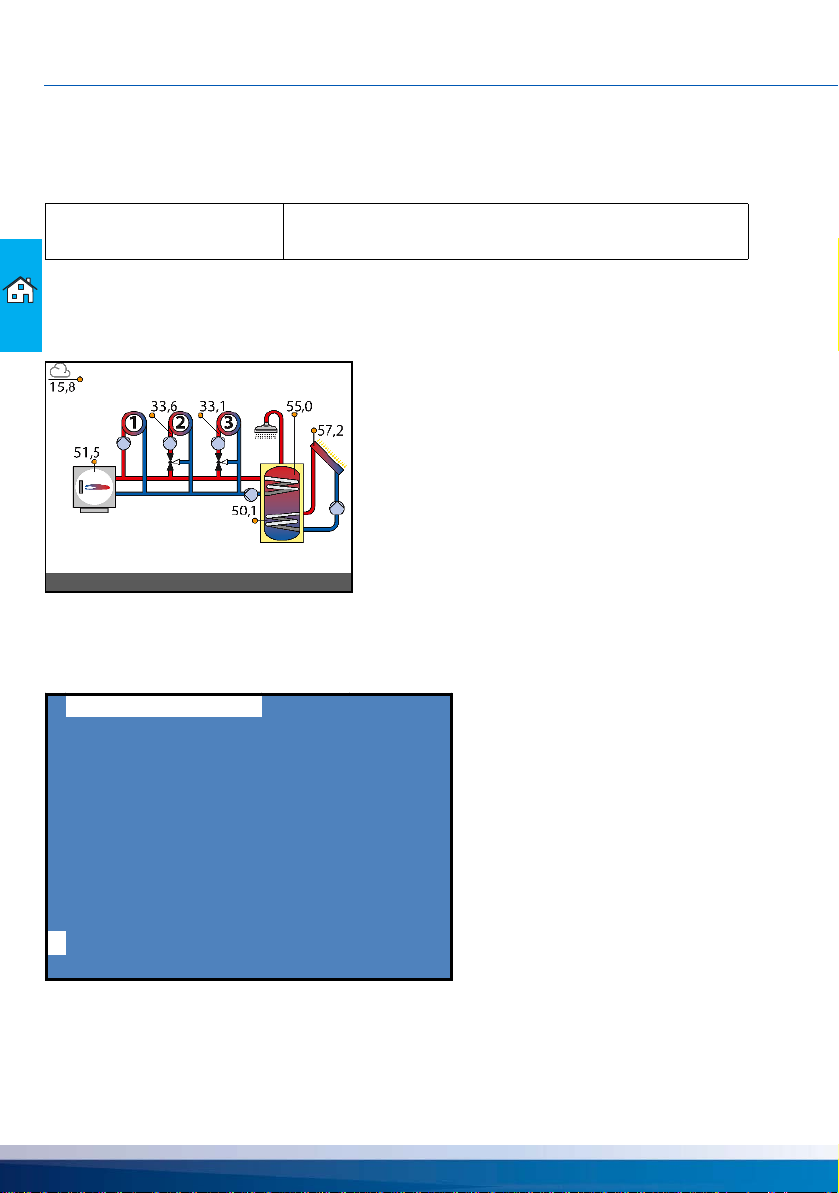
Overview mode
In overview mode, the configured system diagram, sensor temperatures and the operating statuses
of connected components are displayed.
(Example)
Press the rotary/push button to access the menu.
Menu
Check the display screen of the smart Econ on a regular basis
to be able to eliminate any malfunctions promptly!
i
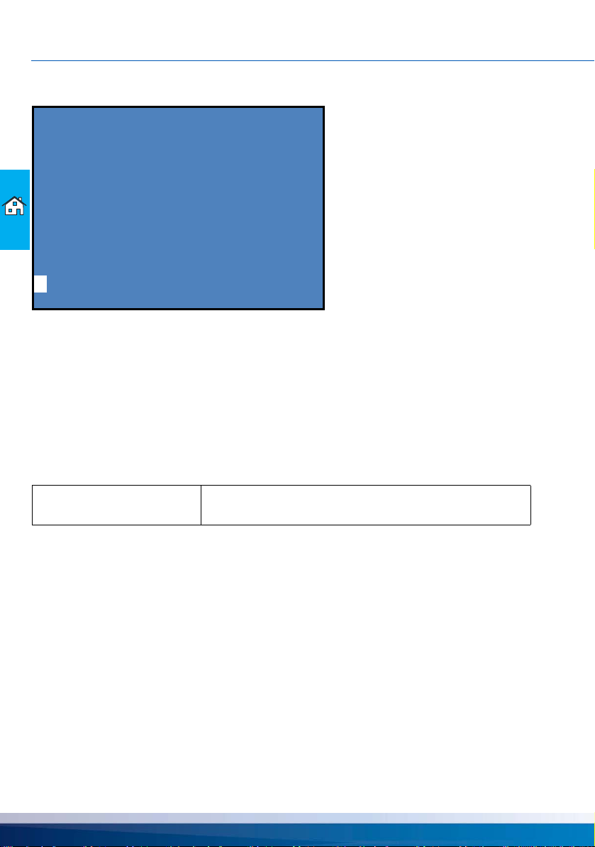
The menu shows the available options for displaying the controller’s temperatures and operating
statuses.
The selected menu item is highlighted.
18 smart Econ - emz-HCW - 180116

PROMPTS DURING OPERATION
Hea t Cir c u its
Temperatures
Outputs
Diagnostics
MENU
BACK
26.02.2018 14:23:03 Server: online AUTOMATIC
Certain menus are divided into several pages, which you can select with the rotary/push button.
The menu item ›BACK‹ always appears in the last line of the last page.
The menu can also be exited by simply pressing the rotary/push button.
On the bottom line, you can see the date and time on the left, status messages in the middle and the
current operating mode on the right.
On the left, the current function of the function keys (1)-(4) is displayed.
See “Control elements” on page 17
Select menu items
• To select the required menu item, scroll through the menu by turning the rotary/push button - the
respective selectable option appears highlighted on the display.
• Pressing the rotary/push button ("OK") confirms the selected menu item.
The respective submenu is opened or the corresponding selection is activated.
• Select ›BACK‹ to jump back one level from any subitem in the menu.
•By pressing the INFO button or by selecting ›INFO‹, you can access help information on the
selected menu item.
Overview menu
i
The overview menu contains the most important information for you to get a quick overview of the
system status.
• Select a submenu.
“›Heat Circuits‹ menu (Overview menu)” on page 20
“›Temperatures‹ menu” on page 21
“›Outputs‹ menu” on page 21
“›Diagnosis‹ menu” on page 22
• Use ›MENU‹ to change settings.
See “Main menu” on page 26
• Select ›BACK‹ to return to the overview mode.
smart Econ - emz-HCW - 180116 19
PROMPTS DURING OPERATION
Hea t Cir c u its
HEAT CIRCUIT 1
*** ON 06:00- 22.00
HEAT CIRCUIT 2
OFF
HEAT CIRCUIT 3
ON 00:00-24.00
BACK
26.02.2018 14:23:03 Server: online AUTOMATIC
›Heat Circuits‹ menu (Overview menu)
i
The ›Heat Circuits‹ menu displays the operating states of all heating circuits in the configured system.
• If the controller is in day mode, the duration programmed for day mode appears to the right of the
current operating status.
If the party function is activated, the time period 00:00 - 24:00 is displayed; no time is displayed in
the setback and frost protection modes.
• If the controller is not in day mode, e.g. outside the programmed time period or if the operating
mode does not permit day mode, nothing appears at this point.
• The ›ON‹/›OFF‹ status indicates whether the heating circuit is ready for operation.
Example: HC 1 =›AUTOMATIC‹, HC 2 =›NIGHT‹, HC 3 =›DAY‹.
NOTE
In the event of a fault, e.g. a defective sensor, three asterisks
*** appear under the relevant heating circuit
20 smart Econ - emz-HCW - 180116

PROMPTS DURING OPERATION
Temperatures
flow heat c irc. 3 <2/22> 36.7
flow heat c irc. 4 <2/24> 44.1
----------------------------damped out-temp. 1.2
BACK
26.02.2018 14:23:03 Server: online AUTOMATIC
Outputs
pump heat circ. 1 <1/36> ON
pump heat circ. 2 <1/38> ON
pump heat circ. 3 <2/36> OFF
pump heat circ. 4 <2/38> OFF
pump dhw <1/34> OFF
pump circ. <2/40> ON
BACK
26.02.2018 14:23:03 Server: online AUTOMATIC
›Temperatures‹ menu
i
The ›Temperatures‹ menu displays the measured or calculated temperature values of the configured system.
The <number> after the input designations shows the number of the connection contact to which the
respective sensor is connected.
Example: ›flow heat circ. 1 <1/20>‹
Designations without <number> are calculated temperature values without connection contact.
Example: ›damped out-temp.‹
›Outputs‹ menu
i
The ›Outputs‹ menu displays the operating statuses ›ON‹/›OFF‹ of the controlled controller outputs
in the configured system.
The <number> after the output designations indicates the number of the switched connection con-
tact.Designations without <number> are logical switching states without connection contact.
smart Econ - emz-HCW - 180116 21
PROMPTS DURING OPERATION
Diagnostics
setpoint-HC 2 21.0
setpoint-HC 3 21.0
setpoint-HC 4 21.0
request heat gen. OFF
DHW PRIORITIY 0.0
i
BACK
26.02.2018 14:23:03 Server: online AUTOM ATIC
Message
MALFUNCTION!
26.02.2018 14:23:03
›Diagnosis‹ menu
The ›Diagnostics‹ menu displays the current states and values of all components and thus of the
entire heat generation process.
The values displayed are logical switching states and calculated values that display the target state
of the control loops.
Error messages
In the event of a fault, an alarm message appears on the display.
Information
i
You can display further information by pressing the function key marked ›i‹.
22 smart Econ - emz-HCW - 180116

SETTINGS DURING OPERATION
Hello user
PLEA S E ENTER YOUR CODE
0000
Settings during operation
Entering the access code
To prevent settings from being changed accidentally, it is necessary to enter an access code for the
smart Econ heating system controller.
In the overview menu (page 19) you can call up the main menu:
• Select ›MENU‹.
You have to enter the access code.
<
>
• Enter the access code for the end user (Code: 0000), if necessary.
See Change values below
• Press the turn knob to confirm.
The main menu is now available. “Main menu” on page 26
Depending on the access code, the corresponding menu items appear.
NOTE
Change values
• Select the value to be changed (e.g. code or temperature) by turning the rotary/push button (highlighted).
• Press the rotary/push button to change the value.
• Use the function keys 2 (<) and 3 (>) to select the digit of the number to be changed (underlined).
Example code: 0000
• Press and turn again to increase or decrease the value.
Example code: 0004
• Press the rotary/push button to confirm the value.
• Repeat the procedure for further digits of the number, if necessary.
The Userinterface does not display any submenus that are not
needed by the selected hydraulic system or the activated
options.
smart Econ - emz-HCW - 180116 23
SETTINGS DURING OPERATION
...
...
...
...
...
...
...
HEIZKREIS 1
SETTINGS
DHW PRIORITY ON/OFF *
TIMER DHW
HEAT CIRCUITS
DOMESTIC HOT WATER **
GENERAL
INTERNET
Overview
Heat Circuits
Temperatures
MENU
INTERNET
serial number
CODE
DHCP
IP-Address
OPERATING MODES
AUTOMATIC
CHIMNEYSWEEP
TIMER PROGRAMS
DOMESTIC HOT WA
TER **
Outputs
Diagnostics
BACK
Enter Code
INSTALLER *
COMMISSIONING
OPERATING HOURS
TEST
HEIZKREIS n
MENU
(Example)
LANGUAGE
DATE + TIME
DELETE ERROR MESSAGE
GENERAL
LANGUAGE *
INSTALLER *
OPERATING MODES
HOLIDAY PERIODS
SETTINGS PUMP DHW *
TIMER CIRCULATION
SETTINGS PUMP CIRC. *
MIN DHW-TEMP CIRC
MAX RF-TEMP CIRC
HEAT CIRCUIT 1
HEAT CIRCUIT n
HOLIDAY PERIODS
ENTIRE UNIT
TIMER PROGRAMS
HEAT CIRCUITS **
global day temp.
HEAT CIRCUIT 1
HEAT CIRCUIT n
global eco temp.
DAY
Menu structure
* Menu items are only available for the installer, see page 108
** Menu depends on the selected system.
24 smart Econ - emz-HCW - 180116

Abbreviations in the menus
Abbreviation Description
ABS Anti-blocking system
CIRC Circulation
DHW Domestic hot water
FL Flow line
HC Heat Circuit
HG Heat generator
HP Heat pump
OT Outside temperature
P Pump
RC Room controller
RL Return line
SFB Solid fuel boilers
SOL Solar
SETTINGS DURING OPERATION
smart Econ - emz-HCW - 180116 25

SETTINGS DURING OPERATION
Main menu
^
OPER A TING MODES
TIMER PROGRAMS
HOLIDA Y PERIODS
HEAT CIRCUITS
DOMESTIC HOT WA TER
GENERA L
i
INT ERN ET
BACK
Main menu
The ›Main menu‹ is displayed after selecting the access code for the end user (Code: 0000).See
“Entering the access code” on page 23
Here you can input settings.
• “›OPERATING MODES‹ menu” on page 27
• “›TIMER PROGRAMS‹ menu” on page 30
• “›HOLIDAY PERIODS‹ menu” on page 35
• “›HEAT CIRCUITS‹ menu” on page 36
• “›DOMESTIC HOT WATER‹ menu” on page 38
• “›GENERAL‹ menu” on page 42
• “›INTERNET‹ menu” on page 44
Note: Additional menu items available for the installer.
“Main menu for the installer” on page 108
26 smart Econ - emz-HCW - 180116

SETTINGS DURING OPERATION
PLEA SE SELECT
ENTIRE UNIT
HEAT CIRCUIT 1
HEAT CIRCUIT 2
HEAT CIRCUIT 3
BACK
PLEA SE SELECT MODE
AUTOMATIC
DA Y
NIGHT
FROST PROTECTION
SUMMER
FLOOR PAVEMENT HEATING
OFF
CHI MNEY S WEEP
BACK
›OPERATING MODES‹ menu
^
i
(Example, depending on the selected system)
In the ›OPERATING MODES‹ menu, first select whether the setting is to apply to the entire system
or only to the individual heating circuit.
^
i
In the menu ›PLEASE SELECT MODE‹ you then define the operating mode for the selected section
of the system.The following modes are possible:
• Operating mode ›AUTOMATIC‹
• Operating mode ›DAY‹
• Operating mode ›NIGHT‹
• Operating mode ›FROST PROTECTION‹
• Operating mode ›SUMMER‹
• Operating mode ›FLOOR PAVEMENT HEATING‹
• Operating mode ›OFF‹
• Operating mode ›CHIMNEY SWEEP‹
smart Econ - emz-HCW - 180116 27

SETTINGS DURING OPERATION
NOTE
Operating mode ›AUTOMATIC‹
System control according to the time programs entered and the chosen ambient temperature setpoints (“›HEAT CIRCUITS‹ menu” on page 36).
The user can make changes with the smart Econ room controller's setting wheel, see “Operating the
smart Econ room controller” on page 16.
As this is set directly at the smart Econ room controller, each user can control the entire heating system for the respective area without requiring any special knowledge of the heating installation or its
control system.
Operating mode ›DAY‹
Time programs are not considered.The highest room temperature setpoint entered for the respective heating circuit is used.
Operating mode ›NIGHT‹
The time programs are not considered, the temperature is always controlled to the room temperature setpoint entered for setback operation.The temperature is also controlled to this setback room
temperature on individual programmed holidays as well as on the last holiday of a holiday period.
See “›HOLIDAY PERIODS‹ menu” on page 35
Operating mode ›FROST PROTECTION‹
Time programs are not considered.The temperature is always controlled to the frost protection room
temperature.
Except for the last day, the temperature is also set to this value during a holiday period.
See “›HOLIDAY PERIODS‹ menu” on page 35
You can change the frost protection temperature directly in the settings of the ›FROST PROTECTION‹ operating mode and it applies to the entire system.
With the exception of the operating modes ›FROST PROTECTION‹ and ›OFF‹, no messages are displayed indicating that
the selected operating mode is active.
The selected operating mode is displayed in the footer.
NOTE
Operating mode ›SUMMER‹
The space heating is off, all other functions (water heating, solar heating system, etc.) are
active.The heating circuit pumps and mixers are switched on briefly once a week to prevent them
from getting stuck when they are not being used regularly during the summer.
Operating mode ›FLOOR PAVEMENT HEATING‹
Note: The ›FLOOR PAVEMENT HEATING‹ mode is only available for heating circuits with mixers.
The frost protection function is always active in all operating
modes except the ›OFF‹ operating mode.
28 smart Econ - emz-HCW - 180116

SETTINGS DURING OPERATION
To be able to properly dry heated screed, the material is heated according to a standardized flow
temperature curve (irrespective of the room temperature).
Note: ›FLOOR PAVEMENT HEATING‹ can be activated with the access code for the end user, but
cannot be set.
Progress of the drying process
day 012345678910
Temperature 20° 25° 30° 35° 40° 40° 40° 40° 40° 30° 20°
Change at midnight every day, regardless of the activation time.
Operating mode ›OFF‹
In this operating mode, all current temperatures and other input information are displayed but no
switching functions are activated.
All components of the system must be switched to inactive!
Operating mode ›CHIMNEY SWEEP‹
In this operating mode, the heating can be switched on immediately at any room temperature.The
boiler is heated up to the highest setpoint entered.
smart Econ - emz-HCW - 180116 29

SETTINGS DURING OPERATION
TIMER PROGRAMS
HEAT CIRCUIT 1
HEAT CIRCUIT 2
HEAT CIRCUIT 3
BACK
TIMER PROGRAMS
HEAT CIRCUIT 1
----------ROOM SETPOINTS
BACK
›TIMER PROGRAMS‹ menu
^
i
(Example, depending on the selected system)
In the ›TIMER PROGRAMS‹ menu, first select the heating circuit to which the setting is to apply.
^
i
Then select ›ROOM SETPOINTS‹.
30 smart Econ - emz-HCW - 180116

SETTINGS DURING OPERATION
HEAT CIRCUIT 1
COPY A LL V A LUES
Monday COPY DAY
from 06:00 - 22:00 hrs => 21 degr
from 00:00 - 00:00 hrs => 21 degr
from 00:00 - 00:01 hrs => 21 degr
economy mode => 15 degr
everything clear NO? => <INFO>!
BACK
^
i
Setting heating periods and temperatures
You can define up to three heating periods for each room and day of the week.
You can define a room temperature for each set period.
In between these periods, the system regulates itself to the setback temperature.
If you set the time from 00:00 to 00:00, the system will not be controlled at this time.
You can enter the times in steps of 10 minutes, the temperatures in steps of 1/10 degree.
Selecting the day of the week
The default setting is ›Monday‹ .
Select the day (shaded) with the turn knob and press the knob. The day will begin to flash.Turn the
turn knob to the left or right and press it to select a different day.
Setting times and temperatures
“Change values” on page 23
›COPY DAY...‹
With the turn knob, select ›COPY DAY...‹ (highlighted) and press the turn knob.A submenu in which
you can select the day of the week is opened.
Example: Tuesday should be the same as on Monday.
Select ›Tuesday‹, press the turn knob, ›COPY DAY...‹, press the turn knob, select ›Monday‹, press
the turn knob.
›COPY ALL VALUES...‹
With the turn knob, select ›COPY ALL VALUES...‹ (highlighted) and press the turn knob.A selection
of additional rooms is displayed.Turn the turn knob again to select a room and press to confirm and
copy all times and temperatures from this room.
smart Econ - emz-HCW - 180116 31

SETTINGS DURING OPERATION
Example:
›HEAT CIRCUIT 1‹ has been defined,
›HEAT CIRCUIT 2‹ should have the same heating times and temperatures.
Select ›HEAT CIRCUIT 2‹, press the turn knob, ›COPY ALL VALUES...‹, press the turn knob, select
›HEAT CIRCUIT 1‹, press the turn knob.
On the following pages, you will find blank forms for rooms in which you can enter the name of the
room, three heating temperature levels with the corresponding heating periods as well as the setback temperature (in between) for your system.
32 smart Econ - emz-HCW - 180116

SETTINGS DURING OPERATION
Table for rooms and heating times
Room:
Day of the week Temperatures and periods
°C °C °C
Monday :- : :- : :- :
Tuesday :- : :- : :- :
Wednesday :- : :- : :- :
Thursday :- : :- : :- :
Friday :- : :- : :- :
Saturday :- : :- : :- :
Sunday :- : :- : :- :
In between: °C (setback temperature)
Room:
Day of the week Temperatures and periods
°C °C °C
Monday :- : :- : :- :
Tuesday :- : :- : :- :
Wednesday :- : :- : :- :
Thursday :- : :- : :- :
Friday :- : :- : :- :
Saturday :- : :- : :- :
Sunday :- : :- : :- :
In between: °C (setback temperature)
smart Econ - emz-HCW - 180116 33

SETTINGS DURING OPERATION
Table for rooms and heating times
Room:
Day of the week Temperatures and periods
°C °C °C
Monday :- : :- : :- :
Tuesday :- : :- : :- :
Wednesday :- : :- : :- :
Thursday :- : :- : :- :
Friday :- : :- : :- :
Saturday :- : :- : :- :
Sunday :- : :- : :- :
In between: °C (setback temperature)
Room:
Day of the week Temperatures and periods
°C °C °C
Monday :- : :- : :- :
Tuesday :- : :- : :- :
Wednesday :- : :- : :- :
Thursday :- : :- : :- :
Friday :- : :- : :- :
Saturday :- : :- : :- :
Sunday :- : :- : :- :
In between: °C (setback temperature)
34 smart Econ - emz-HCW - 180116

SETTINGS DURING OPERATION
PLEA SE SELECT
^
ENTIRE UNIT
HEAT CIRCUIT 1
HEAT CIRCUIT 2
HEAT CIRCUIT 3
HEAT CIRCUIT 4
BACK
i
HOLIDA Y PERIODS
^
ENTIRE UNIT
new holiday f rom 00.00
until 00.00
BACK
i
›HOLIDAY PERIODS‹ menu
(Example, depending on the selected system)
In the ›HOLIDAY PERIODS‹ menu, first select whether the setting is to apply to the entire system or
only to the individual heating circuit.
• Enter the start and end dates for the holiday.
“Change values” on page 23
Notes:
To delete a holiday period, enter the date 00.00.
More than 10 holiday periods can be set for the entire system,
for a single heating circuit, however, only one.
On these holidays, the room temperature is controlled to the frost protection room temperature.
See “Operating mode ›FROST PROTECTION‹” on page 28.
On the last day of a holiday period, the room temperature is controlled to the setback temperature.
If a programmed holiday period has passed, the entry is automatically deleted.
smart Econ - emz-HCW - 180116 35

SETTINGS DURING OPERATION
HEAT CIRCUITS
global day temp. (°C): 22.0
global eco temp. (°C): 18.0
HEAT CIRCUIT 1
HEAT CIRCUIT 2
HEAT CIRCUIT 3
HEAT CIRCUIT 4
BACK
HEAT CIRCUIT 2
SETTINGS ROOM 2
MIXER HEAT CIRC. 2
BACK
›HEAT CIRCUITS‹ menu
^
i
(Example, depending on the selected system)
The ›HEAT CIRCUITS‹ menu shows the global set points and a selection of heating circuits.
• Change the global values applicable to all heating circuits, if necessary.
›global day temp.(°C)‹ = Global setpoint day room temperature for heating periods
›global eco temp.(°C)‹ = Global setpoint night room temperature for setback periods
• Select a heating circuit, e.g. ›HEAT CIRCUIT 2‹ .
Make the settings for the other heating circuits accordingly.
^
i
• Select ›SETTINGS ROOM 2‹ in the ›HEAT CIRCUIT 2‹ menu.
(Example, depending on the selected system)
36 smart Econ - emz-HCW - 180116

SETTINGS DURING OPERATION
SETTINGS ROOM 1
^
NA ME SETTINGS ROOM 1
current set point (°C) 0
use global day temp.: NO
use global eco temp.: NO
ROOM SETPOINTS 0
BACK
i
• Change the name of this temperature sensor if necessary.
• Change the setpoint temperature for this heating circuit, if necessary.
“Change values” on page 23
For further settings, see “›HEAT CIRCUITS‹ menu (Installer)” on page 130
smart Econ - emz-HCW - 180116 37

SETTINGS DURING OPERATION
DOMESTIC HOT WATER
SETTINGS
TIMER DHW
TIMER CIRCULA TION
MIN DHW- TEMP CIRC
MA X RF- TEMP CIRC
BACK
SETTINGS
^
desired value 50
BACK
›DOMESTIC HOT WATER‹ menu
^
i
In the ›DOMESTIC HOT WATER‹ menu you can define the set temperature, the heating times and,
if necessary, the circulation times.
For further settings, see “›DOMESTIC HOT WATER‹ menu (Installer)” on page 135
Setting the domestic hot water setpoint temperature
• Select ›SETTINGS‹ in the ›DOMESTIC HOT WATER‹ menu.
i
• Change the ›desired value‹ (in °C) if necessary.
“Change values” on page 23
38 smart Econ - emz-HCW - 180116

SETTINGS DURING OPERATION
TIMER DHW
^
WEEK L Y PROGRA M
SWITCH TO MA NUA L/ A UTO
BACK
TIMER DHW
^
COPY A LL V A L UES
Monday
sw itch on f rom 06:00 - 22:00 hrs
sw itch on f rom 00:00 - 00:00 hrs
sw itch on f rom 00:00 - 00:00 hrs
Weekly program ENABLED
everything clear NO? => <INFO>!
BACK
Setting the domestic hot water heating times
• To set the heating times, select ›TIMER DHW‹ in the ›DOMESTIC HOT WATER‹ menu.
i
• You can change the heating times via ›WEEKLY PROGRAM‹.
i
• You can define up to three heating times and temperatures for each day of the week.
No heating is used for all times in between.
If you set the time from 00:00 to 00:00, the system will not be controlled at this time.
You can enter the times in steps of 1 minute, the temperatures in steps of 1/10 degree.
“Selecting the day of the week” on page 31
“›COPY DAY...‹” on page 31
“›COPY ALL VALUES...‹” on page 31
• You activate or deactivate the time switch via ›Weekly program: APPROVED‹.
smart Econ - emz-HCW - 180116 39

SETTINGS DURING OPERATION
SCHA LTUHR WW
^
AUTOMATIC (TIMER PROGRAMS)
ALWAYS ON
ALWAYS OFF
BACK
TIMER CIRCULA TION
^
WEEK L Y PROGRA M
BACK
Manual control of domestic hot water heating
• To manually control the heating, select ›SWITCH TO MANUAL/AUTO‹ in the ›TIMER DHW‹
menu.
i
• Select the desired heating mode.
Setting circulation times
• To set the circulation times, select ›TIMER CIRCULATION‹ from the ›DOMESTIC HOT WATER‹
menu.
i
• You can change the circulation times via ›WEEKLY PROGRAM‹ in the same way as for “Setting
the domestic hot water heating times” on page 39.
40 smart Econ - emz-HCW - 180116

SETTINGS DURING OPERATION
MIN DHW- TEMP CIRC
^
limit value 38.0
BACK
MAX RF- TEMP CIRC
^
limit value 38.0
BACK
Configure circulation temperatures
• Select ›MIN DHW-TEMP CIRC‹ in the ›DOMESTIC HOT WATER‹ menu.
i
• Change the ›limit value‹ if necessary.
Minimum storage tank temperature for release of circulation
Circulation setpoint temperature: 38.0 °C (setting range: 0.0 - 95.0)
“Change values” on page 23
• Select ›MAX RF TEMP CIRC‹ in the ›DOMESTIC HOT WATER‹ menu.
i
• Change the ›limit value‹ if necessary.
Maximum temperature in the return line of the circulation
Temperature for stopping the circulation: 38.0 °C (setting range 0.0 - 85.0)
“Change values” on page 23
If the temperature in the return line of the circulation is higher than the set limit value, the circulation
pump is switched off.(The circulation system is flushed.)
smart Econ - emz-HCW - 180116 41

SETTINGS DURING OPERATION
GENERA L
LANGUAGE English T
DA TE + TIME
DELETE ERROR MESSA GE
serial number 12345
softw are version v1.4
firmw are version v1.5
display activ intens ity 80
display dimmed intensity 40
Beeper-Level MAX
--------------------------------------------
DATE + TIME
^
w eek day Wednesday
DA Y 1 7
month 1
year 2018
hour 14
minute 25
second 0
off set -1
BACK
›GENERAL‹ menu
^
i
In the ›GENERAL‹ menu you can view information about Userinterface and change general settings.
For further settings, see “›GENERAL‹ menu (Installer)” on page 140
Setting the language of the menu
• Change the language via ›LANGUAGE‹ if necessary.
“Change values” on page 23
Set date and time
• Select ›DATE + TIME‹ in the ›GENERAL‹ menu.
i
• Set the current date and time.
›offset‹: The time zone can be set here.
“Change values” on page 23
Note: The date and time must be reset after a long power failure.
42 smart Econ - emz-HCW - 180116

SETTINGS DURING OPERATION
dis play activ intensity 80
display dimmed intensity 40
Beeper-Level MAX
--------------------------------------------
Adjusting the display brightness and buzzer volume
i
In the ›GENERAL‹ menu you can adjust the brightness of the LCD display and the volume of the
buzzer:
• ›display active intensity‹: Brightness during operation
• ›display dimmed intensity‹: Brightness in standby mode
• ›Beeper-Level‹: Alarm volume in case of error messages
“Change values” on page 23
smart Econ - emz-HCW - 180116 43

SETTINGS DURING OPERATION
INTERNET
serial number 12345
CODE: xxxxxxxxxxxxxxxxxxxx
renew AUTH-CODE? NO
delete user-data? NO
DHCP Y ES
IP-Address 192.168.1.100
Subnet mask 255.255.255.0
Gateway 192.168.1.1
DNS1 0.0.0.0
DNS2
›INTERNET‹ menu
^
i
0.0.0.0
In the ›INTERNET‹ menu you can view and change the network settings of the Userinterface.
“Change values” on page 23
For further settings, see “›INTERNET‹ menu (Installer)” on page 143
44 smart Econ - emz-HCW - 180116

Installation and connection
INSTALLATION AND CONNECTION
DANGER
Electrical hazard
Danger of death by electrocution!
Before performing any work on the terminals, make sure you
completely disconnect all poles of the power supply and
secure them against being switched on again!
NOTE
Externally secure the consumers that are connected to the
potential-free relay outputs according to their power consumption.
The fuse in the controller only protects the electronic components!
The total load of all pumps or mixers connected to a controller
must not exceed 6 A.
Use flexible connecting cables (stranded wires) only!
smart Econ - emz-HCW - 180116 45

INSTALLATION AND CONNECTION
smart Econ Temperature sensor
Universal sensor elements are available for measuring temperatures.
“smart Econ Temperature sensor” on page 145
These can:
• be plugged into preconfigured thermowells [universal sensors] (supply temperature, boiler temperature, etc.)
• be attached to pipelines [pipe-mounted sensor] (storage tank temperature, flow temperature, etc.)
• be used as smart Econ outside temperature sensor in a weather-resistant housing
If required, you can alternatively use other temperature sensor versions (outside sensor, air duct
sensor, wall mounting room sensor, flush mounting room sensor).
Temperature sensor polarity Terminal
red even terminal number (e.g. 10)
white uneven terminal number (e.g. 11)
The temperature sensors are protected against reverse polarity.If a temperature sensor was connected incorrectly, this will be automatically detected and signaled during startup.Interruptions in the
circuit are also detected and signaled.
Note: If the display shows "polarity reversal", this may also be due to a short circuit in the signal
lines.
NOTE
Only connect temperature sensors and contacts.
Never apply voltage!
46 smart Econ - emz-HCW - 180116

smart Econ HCW
Dimensions smart Econ HCW
220
110 110
INSTALLATION AND CONNECTION
58
218
(dimensions in millimeters)
140
49.6
smart Econ - emz-HCW - 180116 47

INSTALLATION AND CONNECTION
Opening the smart Econ HCW housing
1 Release the lock screw.
2 Swing terminal cover forward ...
3 ... push it upwards ...
4 ... and remove it.
Store the terminal cover carefully and protect it
against damage!
To close the terminal cover, reverse the opening
procedure.
Installation location smart Econ HCW
• In an easily accessible place
• Usual installation height: Display at user eye level
When used for temperature measurement:
• The device must not be exposed to external heat.(Waste heat from electrical appliances, waste
heat from lighting, heated walls, via radiators, etc.)
48 smart Econ - emz-HCW - 180116

Installation smart Econ HCW
INSTALLATION AND CONNECTION
NOTE
Do not use the housing base as drill template.
A device with damaged housing must not be operated!
Screw the shell to the intended installation site.
If necessary, use dowels for wall mounting.
1 Fasten the top securing screw so that a
space of 2 to 3 mm is created between the
wall and the screw head.
2 Move the device so that the upper fastening
port is located above the screw head...
3 ... and push it downwards.
4 Fasten the lower securing screw.
smart Econ - emz-HCW - 180116 49

INSTALLATION AND CONNECTION
CAN bus
→Page 53
Fuse 6.3 A T
Pumps or mixer 230 V AC
2 potential-free relay outputs
Power supply 230 V AC
Temperature sensor
Analog outputs
Vor tex
sensor (no
function)
Spare fuse
Pumps or mixers
2 potential-free
relay outputs
Power
supply
Analog
output
Temperature sensor
CAN bus
→Page 53
Connection smart Econ HCW
Position of the terminals:
Terminal numbers:
“Hydraulic systems and connection diagrams” on page 56
50 smart Econ - emz-HCW - 180116

INSTALLATION AND CONNECTION
Dimensions in mm
smart Econ Room controller
Node number room controller
A multi-digit number is glued on the packaging, on the back of the housing and on the terminal
inside.This is the CAN account number, a unique, unmistakable number, similar to a serial number.
One room controller can be installed per heating circuit in a system.
Each room controller has an individual node number and must be logged into the controller as a bus
device by entering this number, see “Configuring the room controller ›CONFIG RC‹” on page 123.
Make a note of the node numbers!
Dimensions room controller
Opening the room controller housing
First remove the hand wheel, then remove the cover at each corner until the snap lock is
unlocked.To assemble, proceed in reverse order.
Installation location room controller
• As a heating circuit remote control in a reference room.
• As an individual room controller in the respective room.
• Usual installation height: approx. 130 to 140 cm above the top edge of the finished floor.
• Never expose a smart Econ room controller to other heat sources.
Ensure that the installation site is draft-free.
External heat sources could be, for example, direct sunlight, heat generated by electric equipment, heat radiating from lights (halogen spotlights!), heated walls or radiators near the system,
etc.
• Install smart Econ room controllers in a freely accessible place to ensure that its regulatory functions work properly.
smart Econ - emz-HCW - 180116 51

INSTALLATION AND CONNECTION
Cable grommet
CAN bus
Set jumpers for bus termination only for the last
device on the bus line
Installation room controller
Screw smart Econ the room controller directly onto a flush-mounted or cavity wall switch box (hole
spacing 60 mm).
Wall mounting directly above an empty conduit is not recommended.
Room controller connection
The smart Econ room controller is connected to the serial CAN bus.
If a room controller is the last device on a bus line, the jumper for the bus termination must be
set.The jumper must be pulled for all devices in between.
52 smart Econ - emz-HCW - 180116

INSTALLATION AND CONNECTION
1
2
4
3
+
-
L
H
4-pole bus line
CAN bus terminals
Connection CAN-Bus
All devices must be connected in the following sequence.No branches are allowed.
4-pole STP or FTP cable, e.g. J-Y(ST)Y 2 x 2 x 0.6 mm², is recommended as bus cable.
With cables of a correspondingly high quality, the total length of the bus cable can even be several
hundred meters, whereby approx. 20-25 m must be subtracted for each terminal point.
For short distances and sufficient distance (min. 30 cm) to lines carrying mains voltage, unshielded
UTP cable (unshielded twisted pair) can also be used.
NOTE
Cable routing
Lay the following cables:
• 4-pole CAN bus line: serial between smart Econ HCW and room controller with HCW 810,
between base unit - Expansion module - Room controller for HCW 1620
“CAN bus line” on page 15
• Power cable to smart Econ HCW
Optional for networking:
• Ethernet cable to smart Econ Userinterface
Optional configuration:
• USB cable (USB-A / Micro-USB-B) to smart Econ Userinterface
It is important to ensure good grounding of the shielding, as
otherwise the shield can act as an antenna and even amplify
interference on the bus in case of faulty installation, e.g. by
cutting off the shielding foil or the mains.
(1) + = Vss
(2) - = GND
(3) H = CAN High
(4) L = CAN Low
smart Econ - emz-HCW - 180116 53

INSTALLATION AND CONNECTION
Termination in 1st device:
smart Econ HCW
NO jumper
Set the jumper
on the last
device on site!
4-pole CAN bus line
The first device on the CAN bus line must be smart Econ HCW. (The CAN bus of the
smart Econ HCW is already factory terminated, the terminating resistor is permanently installed.
A jumper must be inserted on the last device of the CAN bus line. It is irrelevant at which device
the bus line ends.
Avoid junctions!
Example:
Tip: Never connect more than two cables under one terminal, and only one cable may be connected
between two devices at a time.This automatically results in a serial cable routing.
54 smart Econ - emz-HCW - 180116

INTERNET-BASED NETWORK
Internet-based network
The Ethernet LAN interface can be used to establish a connection to the Internet via a router.
Prerequisites
• Available network connection, establish one if necessary.
• Working network structure
• Static IPv4 address in the home network or
router with DHCP server (usually included in standard routers)
• External access must be configured
NOTE
Router and connection technology has to be provided.The
delivery only includes the smart Econ components.
smart Econ - emz-HCW - 180116 55

HYDRAULIC SYSTEMS AND CONNECTION DIAGRAMS
Hydraulic systems and connection diagrams
NOTE
NOTE
After entering the installer code, in the menu ›INSTALLER‹ - ›COMMISSIONING‹ - ›cur. scheme‹
select one of the following systems that best fits your setup. “Select hydraulic system” on page 111
Further hydraulic systems
Provides a configured system with more functions than are required for your system (e.g. 3 heating
circuits, although your system has only 2 heating circuits, or no solar system connected):
• Deactivate the non-existent temperature sensors in the ›SENSOR ADJUSTING‹ menu.
“Sensor adjustment” on page 121
• Deactivate the non-existent pumps and mixers in the respective menus of the heating circuits or
heat generators.
Note: Only 'non-critical' components can be deactivated, i.e. only sensors and pumps/mixers that
are not absolutely necessary for the selected system.
Example: Hydraulic system 10 results from hydraulic system 8: ›HCW 008 Sol‹ by deactivating the
temperature sensor and the pump for the solar system.
• In ›Curr. System‹ in the ›COMMISSIONING‹ menu, select the hydraulic system ›HCW 008 Sol‹.
“Select hydraulic system” on page 111
• In the menu ›COMMISSIONING‹ - ›SENSOR ADJUSTING‹ -›collector temp.‹ deactivate the nonexistent sensor via ›activated: NO‹.
“Sensor adjustment” on page 121
• In the menu ›COMMISSIONING‹ - ›SOLAR UNIT‹ - ›PUMP SETTINGS‹ deactivate the non-existent pump via ›activated: NO‹.
“Configure solar system” on page 117
This deactivates the functioning of the solar system.
Determine the structure and structure of the system when
planning the entire thermal system and compare the design
with the hydraulic system of the heating system controller!
Observe the terminal assignment stored in the selected system, as this differs from system to system.
The listed systems are NOT assembly instructions and are
incomplete, especially with regard to necessary safety devices
and other components (valves, check valves etc.).
56 smart Econ - emz-HCW - 180116

Hydraulic symbols
Heat pump
Solid fuel boilers
Flow line
Return line
Mixer
Heating circuit
Domestic hot water
Boiler, e.g. fossil fueled
Temperature sensor
Outdoor temperature sensor
Hot water storage tank with heat
exchanger
Pump
Hydraulic separator
Plate heat exchangers
Solar collector panel
HYDRAULIC SYSTEMS AND CONNECTION DIAGRAMS
smart Econ - emz-HCW - 180116 57

HYDRAULIC SYSTEMS AND CONNECTION DIAGRAMS
PE
PE
N
N
L
L
PEPE
PEPE
PEPE
PEPE
N
N
N
N
34
34
48
48
46
46
44
44
42
42
40
40
38
38
36
36
33
33
32
32
31
31
30
30
24
24
10
10
12
12
14
14
16
16
18
18
20
20
22
22
25
25
11
11
13
13
15
15
17
17
19
19
21
21
23
23
4
1
2
3
26
26
5
5
6
6
28
28
7
7
8
8
27
27
29
29
L
L
+
+
-
-
H
H
4
1
2
3
S-OUT <10>
S-FL-HC 2
<22>
S-LP-T <16>
S-DHW
<14>
HG <30>
P-DHW <34>
P-SOL <32>
S-FL-HG
<12>
S-FL-HC 3
<24>
M-HC 2
<42,44>
P-HC 1
<36>
S-COL
<18>
P-HC 2
<38>
P-HC 3
<40>
M-HC 3
<46,48>
AO-HG
0-10V
<28>
PWM P-SOL
<26>
PWM P-SOL <26>
AO-HG 0-10V <28>
S-OUT <10>
S-FL-HG <12>
S-DHW <14>
S-LP-T <16>
S-COL <18>
S-FL-HC 2 <22>
S-FL-HC 3 <24>
M-HC 3 <48>
M-HC 3 <46>
M-HC 2 <44>
M-HC 2 <42>
P-HC 3 <40>
P-HC 2 <38>
P-HC 1 <36>
P-DHW <34>
P-SOL <32>
HG <30>
Temperature sensor
Power supply
230 V AC
Pumps and mixersAnalog
outputs
CAN bus
→Page 53
Hydraulic system 1: ›HCW 001 Sol‹ (HCW 810)
1 heat generator, 1 heating circuit without mixer, 2 heating circuits with mixer,
1 solar collector, 1 domestic hot water tank
Required sensors (PT 1000): 1 outdoor temperature sensor, 2 solar and boiler temperature sensors,
2 storage tank and buffer temperature sensors, 2 flow/return contact temperature sensors
58 smart Econ - emz-HCW - 180116

HYDRAULIC SYSTEMS AND CONNECTION DIAGRAMS
Ter minals Abbre viation Description
6,7 - -
8,9 - -
10,11 S-OUT <10> outdoor temp. <10>
12,13 S-FL-HG <12> f low heat gen. <12>
14,15 S-DHW <14> domest. hot w ater <14>
16,17 S-LP-T <16> low er tank <16>
18,19 S-COL <18> collector temp. <18>
20,21 - -
22,23 S-FL-HC 2 <22> flow heat c irc. 2 <22>
24,25 S-FL-HC 3 <24> flow heat c irc. 3 <24>
26,27 PWM P-SOL <26> PWM pump solar <26>
28,29 AO-HG 0-10V <28> Signal HG 0-10V <28>
30,31 HG <30> Heat Generator <30>
32,33 P-SOL <32> pump solar <32>
34,35 P-DHW <34> pump dhw <34>
36,37 P-HC 1 <36> pump heat circ. 1 <36>
38,39 P-HC 2 <38> pump heat circ. 2 <38>
40,41 P-HC 3 <40> pump heat circ. 3 <40>
42,43 M-HC 2 AUF MIXER HEAT CIRC. 2 OPEN
44 , 4 5 M-HC 2 ZU MIXER HEAT CIRC. 2 CLOSE
46,47 M-HC 3 AUF MIXER HEAT CIRC. 3 OPEN
48 , 4 9 M-HC 3 ZU MIXER HEAT CIRC. 3 CLOSE
“Abbreviations for hydraulic components, inputs and outputs” on page 100
smart Econ - emz-HCW - 180116 59

HYDRAULIC SYSTEMS AND CONNECTION DIAGRAMS
PE
PE
N
N
L
L
PEPE
PEPE
PEPE
PEPE
N
N
N
N
34
34
48
48
46
46
44
44
42
42
40
40
38
38
36
36
33
33
32
32
31
31
30
30
24
24
10
10
12
12
14
14
16
16
18
18
20
20
22
22
25
25
11
11
13
13
15
15
17
17
19
19
21
21
23
23
4
1
2
3
26
26
5
5
6
6
28
28
7
7
8
8
27
27
29
29
L
L
+
+
-
-
H
H
4
1
2
3
P-SFB
<32>
S-FL-SFB
<20>
AO-HG (PWR) <26> *
AO-HG 0-10V <28>
S-OUT <10>
S-FL-HG <12>
S-DHW <14>
S-LP-T <16>
S-FL-SFB <20>
S-FL HC 2 <22>
S-FL HC 3 <24>
M-HC 3 <48>
M-HC 3 <46>
M-HC 2 <44>
M-HC 2 <42>
P-HC 3 <40>
P-HC 2 <38>
P-HC 1 <36>
P-DHW <34>
P-SFB <32>
HG <30>
S-OUT <10>
S-FL-HC 2
<22>
S-LP-T <16>
S-DHW
<14>
HG <30>
P-DHW <34>
S-FL-HG
<12>
S-FL-HC 3
<24>
M-HC 2
<42,44>
P-HC 1
<36>
P-HC 2
<38>
P-HC 3
<40>
M-HC 3
<46,48>
AO-HG
0-10V
<28>
Power supply
230 V AC
CAN bus
→Page 53
Temperature sensor
Pumps and mixers
Analog
outputs
Hydraulic system 2: ›HCW 002 SF‹ (HCW 810)
1 heat generator, 1 solid fuel boiler, 1 heating circuit without mixer,
2 heating circuits with mixer, 1 domestic hot water tank
Required sensors (PT 1000): 1 outdoor temperature sensor, 2 solar and boiler temperature sensors,
2 storage tank and buffer temperature sensors, 2 flow/return contact temperature sensors
* Burner modulation via 0-10 V output at terminals 28 is possible on request.
60 smart Econ - emz-HCW - 180116

HYDRAULIC SYSTEMS AND CONNECTION DIAGRAMS
Ter minals Abbre viation Description
6,7 - -
8,9 - -
10,11 S-OUT <10> outdoor temp. <10>
12,13 S-FL-HG <12> f low heat gen. <12>
14,15 S-DHW <14> domest. hot w ater <14>
16,17 S-LP-T <16> low er tank <16>
18,19 - -
20,21 S-FL-SFB <20> flow s ol fuel gen. <20>
22,23 S-FL-HC 2 <22> flow heat c irc. 2 <22>
24,25 S-FL-HC 3 <24> flow heat c irc. 3 <24>
26,27 --
28,29 AO-HG 0-10V <28> Signal HG 0-10V <28>
30,31 HG <30> Heat Generator <30>
32,33 P-SFB <32> pump solid fuel <32>
34,35 P-DHW <34> pump dhw <34>
36,37 P-HC 1 <36> pump heat circ. 1 <36>
38,39 P-HC 2 <38> pump heat circ. 2 <38>
40,41 P-HC 3 <40> pump heat circ. 3 <40>
42,43 M-HC 2 AUF MIXER HEAT CIRC. 2 OPEN
44 , 4 5 M-HC 2 ZU MIXER HEAT CIRC. 2 CLOSE
46,47 M-HC 3 AUF MIXER HEAT CIRC. 3 OPEN
48 , 4 9 M-HC 3 ZU MIXER HEAT CIRC. 3 CLOSE
“Abbreviations for hydraulic components, inputs and outputs” on page 100
smart Econ - emz-HCW - 180116 61

HYDRAULIC SYSTEMS AND CONNECTION DIAGRAMS
PE
PE
N
N
L
L
PEPE
PEPE
PEPE
PEPE
N
N
N
N
34
34
48
48
46
46
44
44
42
42
40
40
38
38
36
36
33
33
32
32
31
31
30
30
24
24
10
10
12
12
14
14
16
16
18
18
20
20
22
22
25
25
11
11
13
13
15
15
17
17
19
19
21
21
23
23
4
1
2
3
26
26
5
5
6
6
28
28
7
7
8
8
27
27
29
29
L
L
+
+
-
-
H
H
4
1
2
3
P-CIRC
<32>
S-CIRC
<18>
AO-HG (PWR) <26> *
AO-HG 0-10V <28>
S-OUT <10>
S-FL-HG <12>
S-DHW <14>
S-LP-T <16>
S-CIRC <18>
S-FL-HC 2 <22>
S-FL-HC 3 <24>
M-HC 3 <48>
M-HC 3 <46>
M-HC 2 <44>
M-HC 2 <42>
P-HC 3 <40>
P-HC 2 <38>
P-HC 1 <36>
P-DHW <34>
P-CIRC <32>
HG <30>
S-OUT <10>
S-FL-HC 2
<22>
S-DHW
<14>
HG <30>
P-DHW <34>
S-FL-HG
<12>
S-FL-HC 3
<24>
M-HC 2
<42,44>
P-HC 1
<36>
P-HC 2
<38>
P-HC 3
<40>
M-HC 3
<46,48>
AO-HG
0-10V
<28>
S-LP-T
<16>
Power supply
230 V AC
CAN bus
→Page 53
Temperature sensor
Pumps and mixers
Analog
outputs
Hydraulic system 3: ›HCW 003‹ (HCW 810)
1 heat generator, 1 heating circuit without mixer, 2 heating circuits with mixer,
1 domestic hot water tank, domestic hot water circulation
Required sensors (PT 1000): 1 outdoor temperature sensor, 1 solar and boiler temperature sensor,
2 storage tank and buffer temperature sensors, 3 flow/return contact temperature sensors
* Burner modulation via 0-10 V output at terminals 28 is possible on request.
62 smart Econ - emz-HCW - 180116

HYDRAULIC SYSTEMS AND CONNECTION DIAGRAMS
Ter minals Abbre viation Description
6,7 - -
8,9 - -
10,11 S-OUT <10> outdoor temp. <10>
12,13 S-FL-HG <12> f low heat gen. <12>
14,15 S-DHW <14> domest. hot w ater <14>
16,17 S-LP-T <16> low er tank <16>
18,19 S-CIRC <18> circulation <18>
20,21 - -
22,23 S-FL-HC 2 <22> flow heat c irc. 2 <22>
24,25 S-FL-HC 3 <24> flow heat c irc. 3 <24>
26,27 - -
28,29 AO-HG 0-10V <28> Signal HG 0-10V <28>
30,31 HG <30> Heat Generator <30>
32,33 P-CIRC <32> pump circ. <32>
34,35 P-DHW <34> pump dhw <34>
36,37 P-HC 1 <36> pump heat circ. 1 <36>
38,39 P-HC 2 <38> pump heat circ. 2 <38>
40,41 P-HC 3 <40> pump heat circ. 3 <40>
42,43 M-HC 2 AUF MIXER HEAT CIRC. 2 OPEN
44 , 4 5 M-HC 2 ZU MIXER HEAT CIRC. 2 CLOSE
46,47 M-HC 3 AUF MIXER HEAT CIRC. 3 OPEN
48 , 4 9 M-HC 3 ZU MIXER HEAT CIRC. 3 CLOSE
“Abbreviations for hydraulic components, inputs and outputs” on page 100
smart Econ - emz-HCW - 180116 63

HYDRAULIC SYSTEMS AND CONNECTION DIAGRAMS
PE
PE
N
N
L
L
PEPE
PEPE
PEPE
PEPE
N
N
N
N
34
34
48
48
46
46
44
44
42
42
40
40
38
38
36
36
33
33
32
32
31
31
30
30
24
24
10
10
12
12
14
14
16
16
18
18
20
20
22
22
25
25
11
11
13
13
15
15
17
17
19
19
21
21
23
23
4
1
2
3
26
26
5
5
6
6
28
28
7
7
8
8
27
27
29
29
L
L
+
+
-
-
H
H
4
1
2
3
S-CIRC
<24>
P-CIRC
<40>
PWM P-SOL <26>
AO-HG 0-10V <28>
S-OUT <10>
S-FL-HG <12>
S-DHW <14>
S-LP-T <16>
S-COL <18>
S-FL-HC 1 <20>
S-FL-HC 2 <22>
S-CIRC <24>
M-HC 2 <48>
M-HC 2 <46>
M-HC 1 <44>
M-HC 1 <42>
P-CIRC <40>
P-HC 2 <38>
P-HC 1 <36>
P-DHW <34>
P-SOL <32>
HG <30>
S-OUT <10>
S-FLHC 1
<20>
S-LP-T <16>
S-DHW
<14>
HG <30>
P-DHW <34>
P-SOL <32>
S-FL-HG
<12>
S-FL-HC 2
<22>
M-HC 1
<42,44>
P-HC 1
<36>
S-COL
<18>
P-HC 2
<38>
M-HC 2
<46,48>
AO-HG
0-10V
<28>
PWM P-SOL
<26>
Power supply
230 V AC
CAN bus
→Page 53
Temperature sensor
Pumps and mixers
Analog
outputs
Hydraulic system 4: ›HCW 004 Sol‹ (HCW 810)
1 heat generator, 2 heating circuits with mixer, 1 solar collector,
1 domestic hot water tank, domestic hot water circulation
Required sensors (PT 1000): 1 outdoor temperature sensor, 2 solar and boiler temperature sensors,
2 storage tank and buffer temperature sensors, 3 flow/return contact temperature sensors
64 smart Econ - emz-HCW - 180116

HYDRAULIC SYSTEMS AND CONNECTION DIAGRAMS
Ter minals Abbre viation Description
6,7 - -
8,9 - -
10,11 S-OUT <10> outdoor temp. <10>
12,13 S-FL-HG <12> f low heat gen. <12>
14,15 S-DHW <14> domest. hot w ater <14>
16,17 S-LP-T <16> low er tank <16>
18,19 S-COL <18> collector temp. <18>
20,21 S-FL-HC 1 <20> flow heat c irc. 1 <20>
22,23 S-FL-HC 2 <22> flow heat c irc. 2 <22>
24,25 S-CIRC <24> circulation <24>
26,27 PWM P-SOL <26> PWM pump solar <26>
28,29 AO-HG 0-10V <28> Signal HG 0-10V <28>
30,31 HG <30> Heat Generator <30>
32,33 P-SOL <32> pump solar <32>
34,35 P-DHW <34> pump dhw <34>
36,37 P-HC 1 <36> pump heat circ. 1 <36>
38,39 P-HC 2 <38> pump heat circ. 2 <38>
40,41 P-CIRC <40> pump circ. <40>
42,43 M-HC 1 AUF MIXER HEAT CIRC. 1 OPEN
44 , 4 5 M-HC 1 ZU MIXER HEAT CIRC. 1 CLOSE
46,47 M-HC 2 AUF MIXER HEAT CIRC. 2 OPEN
48 , 4 9 M-HC 2 ZU MIXER HEAT CIRC. 2 CLOSE
“Abbreviations for hydraulic components, inputs and outputs” on page 100
smart Econ - emz-HCW - 180116 65

HYDRAULIC SYSTEMS AND CONNECTION DIAGRAMS
PE
PE
N
N
L
L
PEPE
PEPE
PEPE
PEPE
N
N
N
N
34
34
48
48
46
46
44
44
42
42
40
40
38
38
36
36
33
33
32
32
31
31
30
30
24
24
10
10
12
12
14
14
16
16
18
18
20
20
22
22
25
25
11
11
13
13
15
15
17
17
19
19
21
21
23
23
4
1
2
3
26
26
5
5
6
6
28
28
7
7
8
8
27
27
29
29
L
L
+
+
-
-
H
H
4
1
2
3
S-OUT <10>
S-FL-HC 1
<12>
S-LP-T <16>
S-DHW
<14>
HG <30>
P-DHW <34>
P-SOL <32>
S-FL-HG
<12>
S-FL-HC 2
<22>
M-HC 1
<42,44>
P-HC 1
<36>
P-HC 2
<38>
M-HC 2
<46,48>
S-COL
<18>
PWM
P-SOL <26>
AO-HG
0-10V
<28>
P-HG <40>
S-UP-T <24>
PWM P-SOL <26>
AO-HG 0-10V <28>
S-OUT <10>
S-FL-HG <12>
S-DHW <14>
S-LP-T <16>
S-COL <18>
S-FL-HC 1 <20>
S-FL-HC 2 <22>
S-UP-T <24>
M-HC 2 <48>
M-HC 2 <46>
M-HC 1 <44>
M-HC 1 <42>
P-HG <40>
P-HC 2 <38>
P-HC 1 <36>
P-DHW <34>
P-SOL <32>
HG <30>
Power supply
230 V AC
CAN bus
→Page 53
Temperature sensor
Pumps and mixers
Analog
outputs
Hydraulic system 5: ›HCW 005 Sol‹ (HCW 810)
1 heat generator, 2 heating circuits with mixer, 1 solar collector,
1 buffer tank, 1 domestic hot water tank
Required sensors (PT 1000): 1 outdoor temperature sensor, 2 solar and boiler temperature sensors,
3 storage tank and buffer temperature sensors, 2 flow/return contact temperature sensors
66 smart Econ - emz-HCW - 180116

HYDRAULIC SYSTEMS AND CONNECTION DIAGRAMS
Ter minals Abbre viation Description
6,7 - -
8,9 - -
10,11 S-OUT <10> outdoor temp. <10>
12,13 S-FL-HG <12> f low heat gen. <12>
14,15 S-DHW <14> domest. hot w ater <14>
16,17 S-LP-T <16> low er tank <16>
18,19 S-COL <18> collector temp. <18>
20,21 S-FL-HC 1 <20> flow heat c irc. 1 <20>
22,23 S-FL-HC 2 <22> flow heat c irc. 2 <22>
24,25 S-UP-T <24> upper tank <24>
26,27 PWM P-SOL <26> PWM pump solar <26>
28,29 AO-HG 0-10V <28> Signal HG 0-10V <28>
30,31 HG <30> Heat Generator <30>
32,33 P-SOL <32> pump solar <32>
34,35 P-DHW <34> pump dhw <34>
36,37 P-HC 1 <36> pump heat circ. 1 <36>
38,39 P-HC 2 <38> pump heat circ. 2 <38>
40,41 P-HG <40> pump heat gen. <40>
42,43 M-HC 1 AUF MIXER HEAT CIRC. 1 OPEN
44 , 4 5 M-HC 1 ZU MIXER HEAT CIRC. 1 CLOSE
46,47 M-HC 2 AUF MIXER HEAT CIRC. 2 OPEN
48 , 4 9 M-HC 2 ZU MIXER HEAT CIRC. 2 CLOSE
“Abbreviations for hydraulic components, inputs and outputs” on page 100
smart Econ - emz-HCW - 180116 67

HYDRAULIC SYSTEMS AND CONNECTION DIAGRAMS
PE
PE
N
N
L
L
PEPE
PEPE
PEPE
PEPE
N
N
N
N
34
34
48
48
46
46
44
44
42
42
40
40
38
38
36
36
33
33
32
32
31
31
30
30
24
24
10
10
12
12
14
14
16
16
18
18
20
20
22
22
25
25
11
11
13
13
15
15
17
17
19
19
21
21
23
23
4
1
2
3
26
26
5
5
6
6
28
28
7
7
8
8
27
27
29
29
L
L
+
+
-
-
H
H
4
1
2
3
S-OUT <10>
S-FLHC 1
<20>
S-LP-T <16>
S-DHW
<14>
HG <30>
P-HP <34>
S-FL-HG
<12>
S-FL-HC 2
<22>
M-HC 1
<42,44>
P-HC 1
<36>
P-HC 2
<38>
M-HC 2
<46,48>
AO-HG
0-10V
<28>
P-HG <40>
S-MP-T <24>
S-FL-HP
<18>
HP <32>
AO-HG (PWR) <26> *
AO-HG 0-10V <28>
S-OUT <10>
S-FL-HG <12>
S-DHW <14>
S-LP-T <16>
S-FL-HP <18>
S-FL-HC 1 <20>
S-FL-HC 2 <22>
S-MP-T <24>
M-HC 2 <48>
M-HC 2 <46>
M-HC 1 <44>
M-HC 1 <42>
P-HG <40>
P-HC 2 <38>
P-HC 1 <36>
P-HP <34>
HP <32>
HG <30>
Power supply
230 V AC
CAN bus
→Page 53
Temperature sensor
Pumps and mixers
Analog
outputs
Hydraulic system 6: ›HCW 006 HP‹ (HCW 810)
1 heat generator, 1 heat pump, 2 heating circuits with mixer, 1 domestic hot water combi tank
Required sensors (PT 1000): 1 outdoor temperature sensor, 2 solar and boiler temperature sensors,
3 storage tank and buffer temperature sensors, 2 flow/return contact temperature sensors
* Burner modulation via 0-10 V output at terminals 28 is possible on request.
68 smart Econ - emz-HCW - 180116

HYDRAULIC SYSTEMS AND CONNECTION DIAGRAMS
Ter minals Abbre viation Description
6,7 - -
8,9 - -
10,11 S-OUT <10> outdoor temp. <10>
12,13 S-FL-HG <12> f low heat gen. <12>
14,15 S-DHW <14> domest. hot w ater <14>
16,17 S-LP-T <16> low er tank <16>
18,19 S-FL-HP <18> flow heat pump <18>
20,21 S-FL-HC 1 <20> flow heat c irc. 1 <20>
22,23 S-FL-HC 2 <22> flow heat c irc. 2 <22>
24,25 S-MP-T <24> middle tank <24>
26,27 AO-HG (PWR) <26> PWR signal HG % <26>
28,29 AO-HG 0-10V <28> Signal HG 0-10V <28>
30,31 HG <30> Heat Generator <30>
32,33 HP <32> heat pump <32>
34,35 P-HP <34> pump heat pump <34>
36,37 P-HC 1 <36> pump heat circ. 1 <36>
38,39 P-HC 2 <38> pump heat circ. 2 <38>
40,41 P-HG <40> pump heat gen. <40>
42,43 M-HC 1 AUF MIXER HEAT CIRC. 1 OPEN
44 , 4 5 M-HC 1 ZU MIXER HEAT CIRC. 1 CLOSE
46,47 M-HC 2 AUF MIXER HEAT CIRC. 2 OPEN
48 , 4 9 M-HC 2 ZU MIXER HEAT CIRC. 2 CLOSE
“Abbreviations for hydraulic components, inputs and outputs” on page 100
smart Econ - emz-HCW - 180116 69

HYDRAULIC SYSTEMS AND CONNECTION DIAGRAMS
PE
PE
N
N
L
L
PEPE
PEPE
PEPE
PEPE
N
N
N
N
34
34
48
48
46
46
44
44
42
42
40
40
38
38
36
36
33
33
32
32
31
31
30
30
24
24
10
10
12
12
14
14
16
16
18
18
20
20
22
22
25
25
11
11
13
13
15
15
17
17
19
19
21
21
23
23
4
1
2
3
26
26
5
5
6
6
28
28
7
7
8
8
27
27
29
29
L
L
+
+
-
-
H
H
4
1
2
3
S-OUT <10>
S-FL-
SFB
<20>
S-LP-T <16>
S-DHW
<14>
HG <30>
P-DHW <34>
P-SOL
<46>
S-FL-HG
<12>
S-FL-HC 2
<22>
M-HC 2
<42,44>
P-HC 1
<36>
P-HC 2
<38>
S-COL <18>
PWM
P-SOL
<26>
AO-HG
0-10V
<28>
S-UP-T <24>
P-HG
<40>
P-SFB <48>
PWM P-SOL <26>
AO-HG 0-10V <28>
S-OUT <10>
S-FL-HG <12>
S-DHW <14>
S-LP-T <16>
S-COL <18>
S-FL-SFB <20>
S-FL-HC 2 <22>
S-UP-T <24>
P-SFB <48>
P-SOL <46>
M-HC 2 <44>
M-HC 2 <42>
P-HG <40>
P-HC 2 <38>
P-HC 1 <36>
P-DHW <34>
HG <30>
Power supply
230 V AC
CAN bus
→Page 53
Temperature sensor
Pumps and mixers
Analog
outputs
Hydraulic system 7: ›HCW 007 Sol-SF‹ (HCW 810)
1 heat generator, 1 solid fuel boiler, 1 heating circuit with mixer, 1 heating circuit without mixer,
1 solar collector, 1 buffer tank, 1 domestic hot water tank
Required sensors (PT 1000): 1 outdoor temperature sensor, 3 solar and boiler temperature sensors,
3 storage tank and buffer temperature sensors, 1 flow/return contact temperature sensors
70 smart Econ - emz-HCW - 180116

HYDRAULIC SYSTEMS AND CONNECTION DIAGRAMS
Ter minals Abbre viation Description
6,7 - -
8,9 - -
10,11 S-OUT <10> outdoor temp. <10>
12,13 S-FL-HG <12> f low heat gen. <12>
14,15 S-DHW <14> domest. hot w ater <14>
16,17 S-LP-T <16> low er tank <16>
18,19 S-COL <18> collector temp. <18>
20,21 S-FL-SFB <20> flow s ol fuel gen. <20>
22,23 S-FL-HC 2 <22> flow heat c irc. 2 <22>
24,25 S-UP-T <24> upper tank <24>
26,27 PWM P-SOL <26> PWM pump solar <26>
28,29 AO-HG 0-10V <28> Signal HG 0-10V <28>
30,31 HG <30> Heat Generator <30>
32,33 - -
34,35 P-DHW <34> pump dhw <34>
36,37 P-HC 1 <36> pump heat circ. 1 <36>
38,39 P-HC 2 <38> pump heat circ. 2 <38>
40,41 P-HG <40> pump heat gen. <40>
42,43 M-HC 2 AUF MIXER HEAT CIRC. 2 OPEN
44 , 4 5 M-HC 2 ZU MIXER HEAT CIRC. 2 CLOSE
46,47 P-SOL <46> pump solar <46>
48,49 P-SFB <48> pump solid fuel <48>
“Abbreviations for hydraulic components, inputs and outputs” on page 100
smart Econ - emz-HCW - 180116 71

HYDRAULIC SYSTEMS AND CONNECTION DIAGRAMS
PE
PE
N
N
L
L
PEPE
PEPE
PEPE
PEPE
N
N
N
N
34
34
48
48
46
46
44
44
42
42
40
40
38
38
36
36
33
33
32
32
31
31
30
30
24
24
10
10
12
12
14
14
16
16
18
18
20
20
22
22
25
25
11
11
13
13
15
15
17
17
19
19
21
21
23
23
4
1
2
3
26
26
5
5
6
6
28
28
7
7
8
8
27
27
29
29
L
L
+
+
-
-
H
H
4
1
2
3
S-CIRC
<2/10>
P-CIRC
<2/40>
PWM P-SOL <26>
AO-HG 0-10V <28>
S-OUT <10>
S-FL-HG <12>
S-DHW <14>
S-LP-T <16>
S-COL <18>
S-FL-HC 1 <20>
S-FL-HC 2 <22>
M-HC 2 <48>
M-HC 2 <46>
M-HC 1 <44>
M-HC 1 <42>
P-HC 2 <38>
P-HC 1 <36>
P-DHW <34>
STG_2 HG <32>
HG <30>
S-OUT <10>
S-FLHC 1
<20>
S-LP-T <16>
S-DHW
<14>
HG
<30>
P-DHW <34>
P-SOL
<2/34>
S-FL-HG
<12>
S-FL-HC 2
<22>
M-HC 1
<42,44>
P-HC 1
<36>
S-COL
<18>
P-HC 2
<38>
M-HC 2
<46,48>
AO-HG
0-10V
<28>
PWM P-SOL
<26>
STG_2 HG
<32>
Power supply
230 V AC
CAN bus
→Page 53
Temperature sensor
Pumps and mixers
Analog
outputs
Hydraulic system 8: ›HCW 008 Sol‹ (HCW 1620 Base Unit)
1 two-stage heat generator, 4 heating circuits with mixer, 1 solar collector,
1 domestic hot water tank, domestic hot water circulation
Required sensors (PT 1000): 1 outdoor temperature sensor, 2 solar and boiler temperature sensors,
2 storage tank and buffer temperature sensors, 5 flow/return contact temperature sensors
72 smart Econ - emz-HCW - 180116

HYDRAULIC SYSTEMS AND CONNECTION DIAGRAMS
Controller Terminals Abbreviation Des cription
16,7 - -
18,9 - -
1 10,11 S-OUT <1/10> outdoor temp. <1/10>
1 12,13 S-FL-HG <1/12> flow heat gen. <1/12>
1 14,15 S-DHW <1/14> domest. hot w ater <1/14>
1 16,17 S-LP- T <1/16> low er tank <1/16>
1 18,19 S-COL <1/18> collector temp. <1/18>
1 20,21 S-FL-HC 1 <1/20> flow heat c irc. 1 <1/20>
1 22,23 S-FL-HC 2 <1/22> flow heat c irc. 2 <1/22>
1 24,25 - -
1 26,27 PWM P-SOL <1/26> PWM pump solar <1/26>
1 28,29 AO-HG 0-10V <1/28> Signal HG 0-10V <1/28>
1 30,31 HG <1/30> Heat Generator <1/30>
1 32,33 STG_2 HG <1/32> Stage_2 HG <1/32>
1 34,35 P-DHW <1/34> pump dhw <1/34>
1 36,37 P-HC 1 <1/36> pump heat circ. 1 <1/36>
1 38,39 P-HC 2 <1/38> pump heat circ. 2 <1/38>
1 40,41 - -
1 42,43 M-HC 1 A UF MIXER HEAT CIRC. 1 OPEN
1 44,45 M-HC 1 ZU MIXER HEAT CIRC. 1 CLOSE
1 46,47 M-HC 2 A UF MIXER HEAT CIRC. 2 OPEN
1 48,49 M-HC 2 ZU MIXER HEAT CIRC. 2 CLOSE
“Abbreviations for hydraulic components, inputs and outputs” on page 100
smart Econ - emz-HCW - 180116 73

HYDRAULIC SYSTEMS AND CONNECTION DIAGRAMS
PE
PE
N
N
L
L
PEPE
PEPE
PEPE
PEPE
N
N
N
N
34
34
48
48
46
46
44
44
42
42
40
40
38
38
36
36
33
33
32
32
31
31
30
30
24
24
10
10
12
12
14
14
16
16
18
18
20
20
22
22
25
25
11
11
13
13
15
15
17
17
19
19
21
21
23
23
4
1
2
3
26
26
5
5
6
6
28
28
7
7
8
8
27
27
29
29
L
L
+
+
-
-
H
H
4
1
2
3
S-CIRC
<2/10>
P-CIRC
<2/40>
AO-HG (PWR) <2/26> *
S-CIRC <2/10>
S-FL-HC 3 <2/22>
S-FL-HC 4 <2/24>
M-HC 4 <2/48>
M-HC 4 <2/46>
M-HC 3 <2/44>
M-HC 3 <2/42>
P-CIRC <2/40>
P-HC 4 <2/38>
P-HC 3 <2/36>
P-SOL <2/34>
P-SOL
<2/34>
S-FL-HC 3
<2/22>
S-FL-HC 4
<2/24>
M-HC 3 <2/42, 2/44>
M-HC 4
<2/46,2/48>
P-HC 3 <2/36>
P-HC 4
<2/38>
Power supply 230 V AC
CAN bus
→Page 53
Temperature sensor
Pumps and mixers
Analog
outputs
Hydraulic system 8: ›HCW 008 Sol‹ (HCW 1620 Expansion Module)
* Burner modulation via 0-10 V output at terminals 28 is possible on request.
74 smart Econ - emz-HCW - 180116

HYDRAULIC SYSTEMS AND CONNECTION DIAGRAMS
Controller Terminals Abbreviation Des cription
26,7 - -
28,9 - -
2 10,11 S-CIRC <2/10> c irculation <2/10>
2 12,13 - -
2 14,15 - -
2 16,17 - -
2 18,19 - -
2 20,21 - -
2 22,23 S-FL-HC 3 <2/22> flow heat c irc. 3 <2/22>
2 24,25 S-FL-HC 4 <2/24> flow heat c irc. 4 <2/24>
2 26,27 - -
2 28,29 - -
2 30,31 - -
2 32,33 - -
2 34,35 P-SOL <2/34> pump solar <2/34>
2 36,37 P-HC 3 <2/36> pump heat circ. 3 <2/36>
2 38,39 P-HC 4 <2/38> pump heat circ. 4 <2/38>
2 40,41 P-CIRC <2/40> pump circ. <2/40>
2 42,43 M-HC 3 A UF MIXER HEAT CIRC. 3 OPEN
2 44,45 M-HC 3 ZU MIXER HEAT CIRC. 3 CLOSE
2 46,47 M-HC 4 A UF MIXER HEAT CIRC. 4 OPEN
2 48,49 M-HC 4 ZU MIXER HEAT CIRC. 4 CLOSE
“Abbreviations for hydraulic components, inputs and outputs” on page 100
smart Econ - emz-HCW - 180116 75

HYDRAULIC SYSTEMS AND CONNECTION DIAGRAMS
PE
PE
N
N
L
L
PEPE
PEPE
PEPE
PEPE
N
N
N
N
34
34
48
48
46
46
44
44
42
42
40
40
38
38
36
36
33
33
32
32
31
31
30
30
24
24
10
10
12
12
14
14
16
16
18
18
20
20
22
22
25
25
11
11
13
13
15
15
17
17
19
19
21
21
23
23
4
1
2
3
26
26
5
5
6
6
28
28
7
7
8
8
27
27
29
29
L
L
+
+
-
-
H
H
4
1
2
3
S-OUT <10>
S-FL-
SFB
<2/12>
S-LP-T <16>
S-DHW
<14>
HG 1
<30>
P-DHW <34>
P-CIRC
<2/40>
S-FL-HG
<12>
S-FL-HC 2
<22>
M-HC 2
<46,48>
P-HC 1
<36>
P-HC 2
<38>
S-CIRC
<2/10>
AO-HG
0-10V
<28>
S-UP-T <24>
P-HG
<40>
P-SFB
<2/34>
AO-HG 0-10V <28>
S-OUT <10>
S-FL-HG <12>
S-DHW <14>
S-LP-T <16>
S-FL-HC 1 <20>
S-FL-HC 2 <22>
S-UP-T <24>
M-HC 2 <48>
M-HC 2 <46>
M-HC 1 <44>
M-HC 1 <42>
P-HG <40>
P-HC 2 <38>
P-HC 1 <36>
P-DHW <34>
STG_2 HG <32>
HG <30>
S-FL-HC 1
<20>
M-HC 1
<42,44>
STG_2
HG 1
<32>
Power supply
230 V AC
CAN bus
→Page 53
Temperature sen-
Pumps and mixers
Analog
outputs
Hydraulic system 9: ›HCW 009 SF‹ (HCW 1620 Base Unit)
1 two-stage heat generator, 1 solid fuel boiler, 4 heating circuits with mixer,
1 buffer tank, 1 domestic hot water tank, domestic hot water circulation
Required sensors (PT 1000): 1 outdoor temperature sensor, 2 solar and boiler temperature sensors,
3 storage tank and buffer temperature sensors, 5 flow/return contact temperature sensors
76 smart Econ - emz-HCW - 180116

HYDRAULIC SYSTEMS AND CONNECTION DIAGRAMS
Controller Terminals Abbreviation Des cription
16,7 - -
18,9 - -
1 10,11 S-OUT <1/10> outdoor temp. <1/10>
1 12,13 S-FL-HG <1/12> flow heat gen. <1/12>
1 14,15 S-DHW <1/14> domest. hot w ater <1/14>
1 16,17 S-LP- T <1/16> low er tank <1/16>
1 18,19 - -
1 20,21 S-FL-HC 1 <1/20> flow heat c irc. 1 <1/20>
1 22,23 S-FL-HC 2 <1/22> flow heat c irc. 2 <1/22>
1 24,25 S-UP-T <1/24> upper tank <1/24>
1 26,27 - -
1 28,29 AO-HG 0-10V <1/28> Signal HG 0-10V <1/28>
1 30,31 HG <1/30> Heat Generator <1/30>
1 32,33 STG_2 HG <1/32> Stage_2 HG <1/32>
1 34,35 P-DHW <1/34> pump dhw <1/34>
1 36,37 P-HC 1 <1/36> pump heat circ. 1 <1/36>
1 38,39 P-HC 2 <1/38> pump heat circ. 2 <1/38>
1 40,41 P-HG <1/40> pump heat gen. <1/40>
1 42,43 M-HC 1 A UF MIXER HEAT CIRC. 1 OPEN
1 44,45 M-HC 1 ZU MIXER HEAT CIRC. 1 CLOSE
1 46,47 M-HC 2 A UF MIXER HEAT CIRC. 2 OPEN
1 48,49 M-HC 2 ZU MIXER HEAT CIRC. 2 CLOSE
“Abbreviations for hydraulic components, inputs and outputs” on page 100
smart Econ - emz-HCW - 180116 77

HYDRAULIC SYSTEMS AND CONNECTION DIAGRAMS
Power supply
230 V AC
CAN bus
→Page 53
Temperature sensor
Pumps and mixers
Analog
outputs
Hydraulic system 9: ›HCW 009 SF‹ (HCW 1620 Expansion Module)
* Burner modulation via 0-10 V output at terminals 28 is possible on request.
M-HC 4 <2/48>
M-HC 4 <2/46>
M-HC 3 <2/44>
M-HC 3 <2/42>
P-CIRC <2/40>
P-HC 4 <2/38>
P-HC 3 <2/36>
40
40
36
38
36
38
P-SFB <2/34>
34
34
N
N
AO-HG (PWR) <2/26> *
S-CIRC <2/10>
S-FL-SFB <2/12>
12
10
14
12
26
27
26
27
5
5
16
10
28
14
16
28
29
29
7
6
8
15
13
17
7
6
8
15
13
11
17
11
22
18
20
22
18
20
19
21
19
21
23
23
S-FL-HC 3 <2/22>
S-FL-HC 4 <2/24>
24
24
3
1
2
3
1
2
25
25
H
+
-
H
+
-
46
48
44
46
42
48
44
L
N
L
N
4
4
L
L
42
PE
PE
N
N
PEPE
PEPE
PEPE
PEPE
P-CIRC
<2/40>
S-FL-
SFB
<2/12>
P-SFB
<2/34>
S-FL-HC 3
<2/22>
P-HC 3
<2/36>
M-HC 3 <2/42, 2/44>
78 smart Econ - emz-HCW - 180116
S-FL-HC 4
<2/24>
P-HC 4
<-2/38>
M-HC 4
<2/46, 2/48>
S-CIRC
<2/10>

HYDRAULIC SYSTEMS AND CONNECTION DIAGRAMS
Controller Terminals Abbreviation Des cription
26,7 - -
28,9 - -
2 10,11 S-CIRC <2/10> c irculation <2/10>
2 12,13 S-FL-SFB <2/12> flow s ol fuel gen. <2/12>
2 14,15 - -
2 16,17 - -
2 18,19 - -
2 20,21 - -
2 22,23 S-FL-HC 3 <2/22> flow heat c irc. 3 <2/22>
2 24,25 S-FL-HC 4 <2/24> flow heat c irc. 4 <2/24>
2 26,27 - -
2 28,29 - -
2 30,31 - -
2 32,33 - -
2 34,35 P-SFB <2/34> pump solid fuel <2/34>
2 36,37 P-HC 3 <2/36> pump heat circ. 3 <2/36>
2 38,39 P-HC 4 <2/38> pump heat circ. 4 <2/38>
2 40,41 P-CIRC <2/40> pump circ. <2/40>
2 42,43 M-HC 3 A UF MIXER HEAT CIRC. 3 OPEN
2 44,45 M-HC 3 ZU MIXER HEAT CIRC. 3 CLOSE
2 46,47 M-HC 4 A UF MIXER HEAT CIRC. 4 OPEN
2 48,49 M-HC 4 ZU MIXER HEAT CIRC. 4 CLOSE
“Abbreviations for hydraulic components, inputs and outputs” on page 100
smart Econ - emz-HCW - 180116 79

HYDRAULIC SYSTEMS AND CONNECTION DIAGRAMS
PE
PE
N
N
L
L
PEPE
PEPE
PEPE
PEPE
N
N
N
N
34
34
48
48
46
46
44
44
42
42
40
40
38
38
36
36
33
33
32
32
31
31
30
30
24
24
10
10
12
12
14
14
16
16
18
18
20
20
22
22
25
25
11
11
13
13
15
15
17
17
19
19
21
21
23
23
4
1
2
3
26
26
5
5
6
6
28
28
7
7
8
8
27
27
29
29
L
L
+
+
-
-
H
H
4
1
2
3
S-CIRC
<2/10>
P-CIRC
<2/40>
AO-HG 0-10V <28>
S-OUT <10>
S-FL-HG <12>
S-DHW <14>
S-LP-T <16>
S-FL-HC 1 <20>
S-FL-HC 2 <22>
M-HC 2 <48>
M-HC 2 <46>
M-HC 1 <44>
M-HC 1 <42>
P-HC 2 <38>
P-HC 1 <36>
P-DHW <34>
STG_2 HG <32>
HG <30>
S-OUT <10>
S-FLHC 1
<20>
S-LP-T <16>
S-DHW
<14>
HG
<30>
P-DHW <34>
S-FL-HG
<12>
S-FL-HC 2
<22>
M-HC 1
<42,44>
P-HC 1
<36>
P-HC 2
<38>
M-HC 2
<46,48>
AO-HG
0-10V
<28>
STG_2 HG
<32>
Power supply
230 V AC
CAN bus
→Page 53
Temperature sen-
Pumps and mixers
Analog
outputs
Hydraulic system 10: ›HCW 008 Sol‹ (HCW 1620 Base Unit)
(= Hydraulic system 8: ›HCW 008 Sol‹ with solar collector not connected, see page 56)
1 two-stage heat generator, 4 heating circuits with mixer,
1 domestic hot water tank, domestic hot water circulation
Required sensors (PT 1000): 1 outdoor temperature sensor, 1 solar and boiler temperature sensors,
2 storage tank and buffer temperature sensors, 5 flow/return contact temperature sensors
80 smart Econ - emz-HCW - 180116

HYDRAULIC SYSTEMS AND CONNECTION DIAGRAMS
Controller Terminals Abbreviation Des cription
16,7 - -
18,9 - -
1 10,11 S-OUT <1/10> outdoor temp. <1/10>
1 12,13 S-FL-HG <1/12> flow heat gen. <1/12>
1 14,15 S-DHW <1/14> domest. hot w ater <1/14>
1 16,17 S-LP- T <1/16> low er tank <1/16>
1 18,19 - -
1 20,21 S-FL-HC 1 <1/20> flow heat c irc. 1 <1/20>
1 22,23 S-FL-HC 2 <1/22> flow heat c irc. 2 <1/22>
1 24,25 - -
1 26,27 PWM P-SOL <1/26> PWM pump solar <1/26>
1 28,29 AO-HG 0-10V <1/28> Signal HG 0-10V <1/28>
1 30,31 HG <1/30> Heat Generator <1/30>
1 32,33 STG_2 HG <1/32> Stage_2 HG <1/32>
1 34,35 P-DHW <1/34> pump dhw <1/34>
1 36,37 P-HC 1 <1/36> pump heat circ. 1 <1/36>
1 38,39 P-HC 2 <1/38> pump heat circ. 2 <1/38>
1 40,41 - -
1 42,43 M-HC 1 A UF MIXER HEAT CIRC. 1 OPEN
1 44,45 M-HC 1 ZU MIXER HEAT CIRC. 1 CLOSE
1 46,47 M-HC 2 A UF MIXER HEAT CIRC. 2 OPEN
1 48,49 M-HC 2 ZU MIXER HEAT CIRC. 2 CLOSE
“Abbreviations for hydraulic components, inputs and outputs” on page 100
smart Econ - emz-HCW - 180116 81

HYDRAULIC SYSTEMS AND CONNECTION DIAGRAMS
PE
PE
N
N
L
L
PEPE
PEPE
PEPE
PEPE
N
N
N
N
34
34
48
48
46
46
44
44
42
42
40
40
38
38
36
36
33
33
32
32
31
31
30
30
24
24
10
10
12
12
14
14
16
16
18
18
20
20
22
22
25
25
11
11
13
13
15
15
17
17
19
19
21
21
23
23
4
1
2
3
26
26
5
5
6
6
28
28
7
7
8
8
27
27
29
29
L
L
+
+
-
-
H
H
4
1
2
3
S-CIRC
<2/10>
P-CIRC
<2/40>
AO-HG (PWR) <2/26> *
S-CIRC <2/10>
S-FL-HC 3 <2/22>
S-FL-HC 4 <2/24>
M-HC 4 <2/48>
M-HC 4 <2/46>
M-HC 3 <2/44>
M-HC 3 <2/42>
P-CIRC <2/40>
P-HC 4 <2/38>
P-HC 3 <2/36>
S-FL-HC 3
<2/22>
S-FL-HC 4
<2/24>
M-HC 3 <2/42, 2/44>
M-HC 4
<2/46,2/48>
P-HC 3 <2/36>
P-HC 4
<2/38>
Power supply 230 V AC
CAN bus
→Page 53
Temperature sensor
Pumps and mixers
Analog
outputs
Hydraulic system 10: ›HCW 008 Sol‹ (HCW 1620 Expansion Module)
* Burner modulation via 0-10 V output at terminals 28 is possible on request.
82 smart Econ - emz-HCW - 180116

HYDRAULIC SYSTEMS AND CONNECTION DIAGRAMS
Controller Terminals Abbreviation Des cription
26,7 - -
28,9 - -
2 10,11 S-CIRC <2/10> c irculation <2/10>
2 12,13 - -
2 14,15 - -
2 16,17 - -
2 18,19 - -
2 20,21 - -
2 22,23 S-FL-HC 3 <2/22> flow heat c irc. 3 <2/22>
2 24,25 S-FL-HC 4 <2/24> flow heat c irc. 4 <2/24>
2 26,27 - -
2 28,29 - -
2 30,31 - -
2 32,33 - -
2 34,35 - -
2 36,37 P-HC 3 <2/36> pump heat circ. 3 <2/36>
2 38,39 P-HC 4 <2/38> pump heat circ. 4 <2/38>
2 40,41 P-CIRC <2/40> pump circ. <2/40>
2 42,43 M-HC 3 A UF MIXER HEAT CIRC. 3 OPEN
2 44,45 M-HC 3 ZU MIXER HEAT CIRC. 3 CLOSE
2 46,47 M-HC 4 A UF MIXER HEAT CIRC. 4 OPEN
2 48,49 M-HC 4 ZU MIXER HEAT CIRC. 4 CLOSE
“Abbreviations for hydraulic components, inputs and outputs” on page 100
smart Econ - emz-HCW - 180116 83

HYDRAULIC SYSTEMS AND CONNECTION DIAGRAMS
PE
PE
N
N
L
L
PEPE
PEPE
PEPE
PEPE
N
N
N
N
34
34
48
48
46
46
44
44
42
42
40
40
38
38
36
36
33
33
32
32
31
31
30
30
24
24
10
10
12
12
14
14
16
16
18
18
20
20
22
22
25
25
11
11
13
13
15
15
17
17
19
19
21
21
23
23
4
1
2
3
26
26
5
5
6
6
28
28
7
7
8
8
27
27
29
29
L
L
+
+
-
-
H
H
4
1
2
3
S-OUT <10>
S-DHW
<14>
HG 1 <30>
P-DHW <34>
P-CIRC
<2/40>
S-FL-HG
<12>
S-FL-HC 2
<22>
M-HC 2
<46,48>
P-HC 1
<36>
P-HC 2
<38>
S-CIRC
<2/10>
AO-HG 0-10V
<28>
P-HG 1
<40>
P-HG 2 <2/40>
AO-HG (PWR) <2/26> *
AO-HG 0-10V <28>
S-OUT <10>
S-FL-HG <12>
S-DHW <14>
S-FL-HC 1 <20>
S-FL-HC 2 <22>
S-SUM-FL <24>
M-HC 2 <48>
M-HC 2 <46>
M-HC 1 <44>
M-HC 1 <42>
P-HG 1 <40>
P-HC 2 <38>
P-HC 1 <36>
P-DHW <34>
30,31 HG 1 <30>
S-FL-HC 1
<20>
M-HC 1
<42,44>
S-FL-HG 2
<2/12>
AO-HG 2
0-10V
<2/28>
HG 2 <2/30>
S-SUMFL <24>
Power supply
230 V AC
CAN bus
→Page 53
Temperature sen-
Pumps and mixers
Analog
outputs
Hydraulic system 11: ›HCW 011 KAS‹ (HCW 1620 Base Unit)
2 heat generators, heat exchangers, 4 heating circuits with mixer,
1 domestic hot water tank, domestic hot water circulation
Required sensors (PT 1000): 1 outdoor temperature sensor, 2 solar and boiler temperature sensors,
2 storage tank and buffer temperature sensors, 5 flow/return contact temperature sensors
* Burner modulation via 0-10 V output at terminals 28 is possible on request.
84 smart Econ - emz-HCW - 180116

HYDRAULIC SYSTEMS AND CONNECTION DIAGRAMS
Controller Terminals Abbreviation Des cription
16,7 - -
18,9 - -
1 10,11 S-OUT <1/10> outdoor temp. <1/10>
1 12,13 S-FL-HG 1 <1/12> flow heat gen. 1 <1/12>
1 14,15 S-DHW <1/14> domest. hot w ater <1/14>
1 16,17 - -
1 18,19 - -
1 20,21 S-FL-HC 1 <1/20> flow heat c irc. 1 <1/20>
1 22,23 S-FL-HC 2 <1/22> flow heat c irc. 2 <1/22>
1 24,25 S-SUM-FL <1/24> S-SUM-FL <1/24>
1 26,27 - -
1 28,29 AO-HG 0-10V <1/28> Signal HG 0-10V <1/28>
1 30,31 HG 1 <1/30> Heat Generator 1 <1/30>
1 32,33 - -
1 34,35 P-DHW <1/34> pump dhw <1/34>
1 36,37 P-HC 1 <1/36> pump heat circ. 1 <1/36>
1 38,39 P-HC 2 <1/38> pump heat circ. 2 <1/38>
1 40,41 P-HG 1 <1/40> pump heat gen. 1 <1/40>
1 42,43 M-HC 1 A UF MIXER HEAT CIRC. 1 OPEN
1 44,45 M-HC 1 ZU MIXER HEAT CIRC. 1 CLOSE
1 46,47 M-HC 2 A UF MIXER HEAT CIRC. 2 OPEN
1 48,49 M-HC 2 ZU MIXER HEAT CIRC. 2 CLOSE
“Abbreviations for hydraulic components, inputs and outputs” on page 100
smart Econ - emz-HCW - 180116 85

HYDRAULIC SYSTEMS AND CONNECTION DIAGRAMS
PE
PE
N
N
L
L
PEPE
PEPE
PEPE
PEPE
N
N
N
N
34
34
48
48
46
46
44
44
42
42
40
40
38
38
36
36
24
24
10
10
12
12
14
14
16
16
18
18
20
20
22
22
25
25
11
11
13
13
15
15
17
17
19
19
21
21
23
23
4
1
2
3
26
26
5
5
6
6
28
28
7
7
8
8
27
27
29
29
L
L
+
+
-
-
H
H
4
1
2
3
AO-HG (PWR) <2/26> *
AO-HG (0-10V) <2/28>
S-CIRC <2/10>
S-FL-HG 2 <2/12>
S-FL-HC 3 <2/22>
S-FL-HC 4 <2/24>
M-HC 4 <2/48>
M-HC 4 <2/46>
M-HC 3 <2/44>
M-HC 3 <2/42>
P-CIRC <2/40>
P-HC 4 <2/38>
P-HC 3 <2/36>
P-HG 2 <2/34>
S-FL-HC 3
<2/22>
S-FL-HC 4
<2/24>
M-HC 3 <2/42, 2/44>
M-HC 4
<2/46, 2/48>
P-HC 3
<2/36>
P-HC 4
<2/38>
HG 2 <2/30>
P-CIRC
<2/40>
S-CIRC
<2/10>
P-HG 2
<2/40>
S-FLHG 2
<2/12>
AO-HG
0-10V
<2/28>
HG 2
<2/30>
Power supply
230 V AC
CAN bus
→Page 53
Temperature sensor
Pumps and mixers
Analog
outputs
Hydraulic system 11: ›HCW 011 KAS‹ (HCW 1620 Expansion Module)
* Burner modulation via 0-10 V output at terminals 28 is possible on request.
86 smart Econ - emz-HCW - 180116

HYDRAULIC SYSTEMS AND CONNECTION DIAGRAMS
Controller Terminals Abbreviation Description
26,7 - -
28,9 - -
2 10,11 S-CIRC <2/10> circulation <2/10>
2 12,13 S-FL-HG 2 <2/12> flow heat gen. 2 <2/12>
2 14,15 - -
2 16,17 - -
2 18,19 - -
2 20,21 - -
2 22,23 S-FL-HC 3 <2/22> f low heat circ. 3 <2/22>
2 24,25 S-FL-HC 4 <2/24> f low heat circ. 4 <2/24>
2 26,27 - -
2 28,29 AO-HG 0-10V <2/28> Signal HG 0-10V <2/28>
2 30,31 HG 2 <2/30> Heat Generator 2 <2/30>
2 32,33 - -
2 34,35 P-HG 2 <2/34> pump heat gen. 2 <2/34>
2 36,37 P-HC 3 <2/36> pump heat circ. 3 <2/36>
2 38,39 P-HC 4 <2/38> pump heat circ. 4 <2/38>
2 40,41 P-CIRC <2/40> pump circ. <2/40>
2 42,43 M-HC 3 AUF MIXER HEA T CIRC. 3 OPEN
2 44,45 M-HC 3 ZU MIXER HEA T CIRC. 3 CLOSE
2 46,47 M-HC 4 AUF MIXER HEA T CIRC. 4 OPEN
2 48,49 M-HC 4 ZU MIXER HEA T CIRC. 4 CLOSE
“Abbreviations for hydraulic components, inputs and outputs” on page 100
smart Econ - emz-HCW - 180116 87

HYDRAULIC SYSTEMS AND CONNECTION DIAGRAMS
PE
PE
N
N
L
L
PEPE
PEPE
PEPE
PEPE
N
N
N
N
34
34
48
48
46
46
44
44
42
42
40
40
38
38
36
36
33
33
32
32
31
31
30
30
24
24
10
10
12
12
14
14
16
16
18
18
20
20
22
22
25
25
11
11
13
13
15
15
17
17
19
19
21
21
23
23
4
1
2
3
26
26
5
5
6
6
28
28
7
7
8
8
27
27
29
29
L
L
+
+
-
-
H
H
4
1
2
3
S-OUT <10>
S-LP-T <16>
S-DHW
<14>
HG <30>
P-DHW <34>
P-CIRC
<2/40>
S-FL-HG
<12>
S-FL-HC 2
<22>
M-HC 2
<46,48>
P-HC 1
<36>
P-HC 2
<38>
S-CIRC
<2/10>
AO-HG
0-10V
<28>
S-UP-T <24>
P-HG
<40>
PWM P-SOL <26>
AO-HG 0-10V <28>
S-OUT <10>
S-FL-HG <12>
S-DHW <14>
S-LP-T <16>
S-COL <18>
S-FL-HC 1 <20>
S-FL-HC 2 <22>
S-UP-T <24>
M-HC 2 <48>
M-HC 2 <46>
M-HC 1 <44>
M-HC 1 <42>
P-HG <40>
P-HC 2 <38>
P-HC 1 <36>
P-DHW <34>
STG_2 HG <32>
HG <30>
S-FL-HC 1
<20>
M-HC 1
<42,44>
STG_2
HG <32>
S-COL
<18>
P-SOL
<2/32>
PWM
P-SOL
<26>
Power supply
230 V AC
CAN bus
→Page 53
Temperature sensor
Pumps and mixers
Analog
outputs
Hydraulic system 12: ›HCW 012 Sol‹ (HCW 1620 Base Unit)
1 two-stage heat generator, 4 heating circuits with mixer, 1 solar collector,
1 buffer tank, 1 domestic hot water tank, domestic hot water circulation
Required sensors (PT 1000): 1 outdoor temperature sensor, 2 solar and boiler temperature sensors,
3 storage tank and buffer temperature sensors, 5 flow/return contact temperature sensors
88 smart Econ - emz-HCW - 180116

HYDRAULIC SYSTEMS AND CONNECTION DIAGRAMS
Controller Terminals Abbreviation Des cription
16,7 - -
18,9 - -
1 10,11 S-OUT <1/10> outdoor temp. <1/10>
1 12,13 S-FL-HG <1/12> flow heat gen. <1/12>
1 14,15 S-DHW <1/14> domest. hot w ater <1/14>
1 16,17 S-LP- T <1/16> low er tank <1/16>
1 18,19 S-COL <1/18> collector temp. <1/18>
1 20,21 S-FL-HC 1 <1/20> flow heat c irc. 1 <1/20>
1 22,23 S-FL-HC 2 <1/22> flow heat c irc. 2 <1/22>
1 24,25 S-UP-T <1/24> upper tank <1/24>
1 26,27 PWM P-SOL <1/26> PWM pump solar <1/26>
1 28,29 AO-HG 0-10V <1/28> Signal HG 0-10V <1/28>
1 30,31 HG <1/30> Heat Generator <1/30>
1 32,33 STG_2 HG <1/32> Stage_2 HG <1/32>
1 34,35 P-DHW <1/34> pump dhw <1/34>
1 36,37 P-HC 1 <1/36> pump heat circ. 1 <1/36>
1 38,39 P-HC 2 <1/38> pump heat circ. 2 <1/38>
1 40,41 P-HG <1/40> pump heat gen. <1/40>
1 42,43 M-HC 1 A UF MIXER HEAT CIRC. 1 OPEN
1 44,45 M-HC 1 ZU MIXER HEAT CIRC. 1 CLOSE
1 46,47 M-HC 2 A UF MIXER HEAT CIRC. 2 OPEN
1 48,49 M-HC 2 ZU MIXER HEAT CIRC. 2 CLOSE
“Abbreviations for hydraulic components, inputs and outputs” on page 100
smart Econ - emz-HCW - 180116 89

HYDRAULIC SYSTEMS AND CONNECTION DIAGRAMS
PE
PE
N
N
L
L
PEPE
PEPE
PEPE
PEPE
N
N
N
N
34
34
48
48
46
46
44
44
42
42
40
40
38
38
36
36
24
24
10
10
12
12
14
14
16
16
18
18
20
20
22
22
25
25
11
11
13
13
15
15
17
17
19
19
21
21
23
23
4
1
2
3
26
26
5
5
6
6
28
28
7
7
8
8
27
27
29
29
L
L
+
+
-
-
H
H
4
1
2
3
P-CIRC
<2/40>
S-CIRC
<2/10>
AO-HG (PWR) <2/26> *
S-CIRC <2/10>
S-FL-HC 3 <2/22>
S-FL-HC 4 <2/24>
M-HC 4 <2/48>
M-HC 4 <2/46>
M-HC 3 <2/44>
M-HC 3 <2/42>
P-CIRC <2/40>
P-HC 4 <2/38>
P-HC 3 <2/36>
S-FL-HC 3
<2/22>
S-FL-HC 4
<2/24>
M-HC 3 <2/42, 2/44>
M-HC 4
<2/46, 2/48>
P-HC 3
<2/36>
P-HC 4
<2/38>
P-SOL <2/32>
P-SOL
<2/32>
Power supply
230 V AC
CAN bus
→Page 53
Temperature sensor
Pumps and mixers
Analog
outputs
Hydraulic system 12: ›HCW 012 Sol‹ (HCW 1620 Expansion Module)
* Burner modulation via 0-10 V output at terminals 28 is possible on request.
90 smart Econ - emz-HCW - 180116

HYDRAULIC SYSTEMS AND CONNECTION DIAGRAMS
Controller Terminals Abbreviation Des cription
26,7 - -
28,9 - -
2 10,11 S-CIRC <2/10> c irculation <2/10>
2 12,13 - -
2 14,15 - -
2 16,17 - -
2 18,19 - -
2 20,21 - -
2 22,23 S-FL-HC 3 <2/22> flow heat c irc. 3 <2/22>
2 24,25 S-FL-HC 4 <2/24> flow heat c irc. 4 <2/24>
2 26,27 - -
2 28,29 - -
2 30,31 - -
2 32,33 - -
2 34,35 P-SOL <2/34> pump solar <2/34>
2 36,37 P-HC 3 <2/36> pump heat circ. 3 <2/36>
2 38,39 P-HC 4 <2/38> pump heat circ. 4 <2/38>
2 40,41 P-CIRC <2/40> pump circ. <2/40>
2 42,43 M-HC 3 A UF MIXER HEAT CIRC. 3 OPEN
2 44,45 M-HC 3 ZU MIXER HEAT CIRC. 3 CLOSE
2 46,47 M-HC 4 A UF MIXER HEAT CIRC. 4 OPEN
2 48,49 M-HC 4 ZU MIXER HEAT CIRC. 4 CLOSE
“Abbreviations for hydraulic components, inputs and outputs” on page 100
smart Econ - emz-HCW - 180116 91

HYDRAULIC SYSTEMS AND CONNECTION DIAGRAMS
PE
PE
N
N
L
L
PEPE
PEPE
PEPE
PEPE
N
N
N
N
34
34
48
48
46
46
44
44
42
42
40
40
38
38
36
36
33
33
32
32
31
31
30
30
24
24
10
10
12
12
14
14
16
16
18
18
20
20
22
22
25
25
11
11
13
13
15
15
17
17
19
19
21
21
23
23
4
1
2
3
26
26
5
5
6
6
28
28
7
7
8
8
27
27
29
29
L
L
+
+
-
-
H
H
4
1
2
3
S-OUT <10>
S-FL-
HP
<2/12>
S-LP-T <16>
S-DHW
<14>
HG <30>
P-DHW <34>
P-CIRC
<2/40>
S-FL-HG
<12>
S-FL-HC 2
<22>
M-HC 2
<46,48>
P-HC 1
<36>
P-HC 2
<38>
S-CIRC
<2/10>
AO-HG
0-10V
<28>
S-UP-T <24>
P-HG
<40>
P-HP
<2/34>
AO-HG 0-10V <28>
S-OUT <10>
S-FL-HG <12>
S-DHW <14>
S-LP-T <16>
S-FL-HC 1 <20>
S-FL-HC 2 <22>
S-UP-T <24>
M-HC 2 <48>
M-HC 2 <46>
M-HC 1 <44>
M-HC 1 <42>
P-HG <40>
P-HC 2 <38>
P-HC 1 <36>
P-DHW <34>
STG_2 HG <32>
HG <30>
S-FL-HC 1
<20>
M-HC 1
<42,44>
STG_2
HG <32>
HP <2/30>
Power supply
230 V AC
CAN bus
→Page 53
Temperature sensor
Pumps and mixers
Analog
outputs
Hydraulic system 13: ›HCW 013 HP‹ (HCW 1620 Base Unit)
1 two-stage heat generator, 1 heat pump, 4 heating circuits with mixer,
1 buffer tank, 1 domestic hot water tank, domestic hot water circulation
Required sensors (PT 1000): 1 outdoor temperature sensor, 2 solar and boiler temperature sensors,
3 storage tank and buffer temperature sensors, 5 flow/return contact temperature sensors
92 smart Econ - emz-HCW - 180116

HYDRAULIC SYSTEMS AND CONNECTION DIAGRAMS
Controller Terminals Abbreviation Des cription
16,7 - -
18,9 - -
1 10,11 S-OUT <1/10> outdoor temp. <1/10>
1 12,13 S-FL-HG <1/12> flow heat gen. <1/12>
1 14,15 S-DHW <1/14> domest. hot w ater <1/14>
1 16,17 S-LP- T <1/16> low er tank <1/16>
1 18,19 - -
1 20,21 S-FL-HC 1 <1/20> flow heat c irc. 1 <1/20>
1 22,23 S-FL-HC 2 <1/22> flow heat c irc. 2 <1/22>
1 24,25 S-UP-T <1/24> upper tank <1/24>
1 26,27 - -
1 28,29 AO-HG 0-10V <1/28> Signal HG 0-10V <1/28>
1 30,31 HG <1/30> Heat Generator <1/30>
1 32,33 STG_2 HG <1/32> Stage_2 HG <1/32>
1 34,35 P-DHW <1/34> pump dhw <1/34>
1 36,37 P-HC 1 <1/36> pump heat circ. 1 <1/36>
1 38,39 P-HC 2 <1/38> pump heat circ. 2 <1/38>
1 40,41 P-HG <1/40> pump heat gen. <1/40>
1 42,43 M-HC 1 A UF MIXER HEAT CIRC. 1 OPEN
1 44,45 M-HC 1 ZU MIXER HEAT CIRC. 1 CLOSE
1 46,47 M-HC 2 A UF MIXER HEAT CIRC. 2 OPEN
1 48,49 M-HC 2 ZU MIXER HEAT CIRC. 2 CLOSE
“Abbreviations for hydraulic components, inputs and outputs” on page 100
smart Econ - emz-HCW - 180116 93

HYDRAULIC SYSTEMS AND CONNECTION DIAGRAMS
PE
PE
N
N
L
L
PEPE
PEPE
PEPE
PEPE
N
N
N
N
34
34
48
48
46
46
44
44
42
42
40
40
38
38
36
36
24
24
10
10
12
12
14
14
16
16
18
18
20
20
22
22
25
25
11
11
13
13
15
15
17
17
19
19
21
21
23
23
4
1
2
3
26
26
5
5
6
6
28
28
7
7
8
8
27
27
29
29
L
L
+
+
-
-
H
H
4
1
2
3
S-FLHP
<2/12>
P-CIRC
<2/40>
S-CIRC
<2/10>
P-HP
<2/34>
AO-HG (PWR) <2/26> *
S-CIRC <2/10>
S-FL-HP <2/12>
S-FL-HC 3 <2/22>
S-FL-HC 4 <2/24>
M-HC 4 <2/48>
M-HC 4 <2/46>
M-HC 3 <2/44>
M-HC 3 <2/42>
P-CIRC <2/40>
P-HC 4 <2/38>
P-HC 3 <2/36>
P-HP <2/34>
S-FL-HC 3
<2/22>
S-FL-HC 4
<2/24>
M-HC 3 <2/42, 2/44>
M-HC 4
<2/46, 2/48>
P-HC 3
<2/36>
P-HC 4
<2/38>
HP <2/30>
HP <2/30>
Power supply
230 V AC
CAN bus
→Page 53
Temperature sensor
Pumps and mixers
Analog
outputs
Hydraulic system 13: ›HCW 013 HP‹ (HCW 1620 Expansion Module)
* Burner modulation via 0-10 V output at terminals 28 is possible on request.
94 smart Econ - emz-HCW - 180116

HYDRAULIC SYSTEMS AND CONNECTION DIAGRAMS
Controller Terminals Abbreviation Description
26,7 - -
28,9 - -
2 10,11 S-CIRC <2/10> circulation <2/10>
2 12,13 S-FL-HP <2/12> flow heat pump <2/12>
2 14,15 - -
2 16,17 - -
2 18,19 - -
2 20,21 - -
2 22,23 S-FL-HC 3 <2/22> f low heat circ. 3 <2/22>
2 24,25 S-FL-HC 4 <2/24> f low heat circ. 4 <2/24>
2 26,27 - -
2 28,29 - -
2 30,31 HP <2/30> heat pump <2/30>
2 32,33 - -
2 34,35 P-HP 2 <2/34> pump heat pump 2 <2/34>
2 36,37 P-HC 3 <2/36> pump heat circ. 3 <2/36>
2 38,39 P-HC 4 <2/38> pump heat circ. 4 <2/38>
2 40,41 P-CIRC <2/40> pump circ. <2/40>
2 42,43 M-HC 3 AUF MIXER HEA T CIRC. 3 OPEN
2 44,45 M-HC 3 ZU MIXER HEA T CIRC. 3 CLOSE
2 46,47 M-HC 4 AUF MIXER HEA T CIRC. 4 OPEN
2 48,49 M-HC 4 ZU MIXER HEA T CIRC. 4 CLOSE
“Abbreviations for hydraulic components, inputs and outputs” on page 100
smart Econ - emz-HCW - 180116 95

HYDRAULIC SYSTEMS AND CONNECTION DIAGRAMS
PE
PE
N
N
L
L
PEPE
PEPE
PEPE
PEPE
N
N
N
N
34
34
48
48
46
46
44
44
42
42
40
40
38
38
36
36
33
33
32
32
31
31
30
30
24
24
10
10
12
12
14
14
16
16
18
18
20
20
22
22
25
25
11
11
13
13
15
15
17
17
19
19
21
21
23
23
4
1
2
3
26
26
5
5
6
6
28
28
7
7
8
8
27
27
29
29
L
L
+
+
-
-
H
H
4
1
2
3
S-OUT <10>
S-FL-
SFB
<2/12>
S-LP-T <16>
S-DHW
<14>
HG <30>
P-DHW <34>
P-CIRC
<2/40>
S-FL-HG
<12>
S-FL-HC 2
<22>
M-HC 2
<46,48>
P-HC 1
<36>
P-HC 2
<38>
S-CIRC
<2/10>
AO-HG
0-10V
<28>
S-UP-T <24>
P-HG
<40>
P-SFB <48>
PWM P-SOL <26>
AO-HG 0-10V <28>
S-OUT <10>
S-FL-HG <12>
S-DHW <14>
S-LP-T <16>
S-COL <18>
S-FL-HC 2 <22>
S-UP-T <24>
M-HC 1 <48>
M-HC 1 <46>
P-SFB <48>
P-HG <40>
P-HC 2 <38>
P-HC 1 <36>
P-DHW <34>
STG_2 HG <32>
HG <30>
STG_2
HG <32>
P-SOL
<2/34>
S-COL
<18>
PWM
P-SOL
<26>
Power supply
230 V AC
CAN bus
→Page 53
Temperature sensor
Pumps and mixers
Analog
outputs
Hydraulic system 14: ›HCW 014 Sol-SF‹ (HCW 1620 Base Unit)
1 two-stage heat generator, 1 solid fuel boiler, 4 heating circuits with mixer,
1 solar collector, 1 buffer tank, 1 domestic hot water tank, domestic hot water circulation
Required sensors (PT 1000): 1 outdoor temperature sensor, 3 solar and boiler temperature sensors,
2 storage tank and buffer temperature sensors, 5 flow/return contact temperature sensors
96 smart Econ - emz-HCW - 180116

HYDRAULIC SYSTEMS AND CONNECTION DIAGRAMS
Controller Terminals Abbreviation Des cription
16,7 - -
18,9 - -
1 10,11 S-OUT <1/10> outdoor temp. <1/10>
1 12,13 S-FL-HG <1/12> flow heat gen. <1/12>
1 14,15 S-DHW <1/14> domest. hot w ater <1/14>
1 16,17 S-LP- T <1/16> low er tank <1/16>
1 18,19 S-COL <1/18> collector temp. <1/18>
1 20,21 - -
1 22,23 S-FL-HC 2 <1/22> flow heat c irc. 2 <1/22>
1 24,25 S-UP-T <1/24> upper tank <1/24>
1 26,27 PWM P-SOL <1/26> PWM pump solar <1/26>
1 28,29 AO-HG 0-10V <1/28> Signal HG 0-10V <1/28>
1 30,31 HG <1/30> Heat Generator <1/30>
1 32,33 STG_2 HG <1/32> Stage_2 HG <1/32>
1 34,35 P-DHW <1/34> pump dhw <1/34>
1 36,37 P-HC 1 <1/36> pump heat circ. 1 <1/36>
1 38,39 P-HC 2 <1/38> pump heat circ. 2 <1/38>
1 40,41 P-HG <1/40> pump heat gen. <1/40>
1 42,43 P-SFB <1/42> pump solid fuel <1/42>
1 44,45 - -
1 46,47 M-HC 2 A UF MIXER HEAT CIRC. 2 OPEN
1 48,49 M-HC 2 ZU MIXER HEAT CIRC. 2 CLOSE
“Abbreviations for hydraulic components, inputs and outputs” on page 100
smart Econ - emz-HCW - 180116 97

HYDRAULIC SYSTEMS AND CONNECTION DIAGRAMS
PE
PE
N
N
L
L
PEPE
PEPE
PEPE
PEPE
N
N
N
N
34
34
48
48
46
46
44
44
42
42
40
40
38
38
36
36
24
24
10
10
12
12
14
14
16
16
18
18
20
20
22
22
25
25
11
11
13
13
15
15
17
17
19
19
21
21
23
23
4
1
2
3
26
26
5
5
6
6
28
28
7
7
8
8
27
27
29
29
L
L
+
+
-
-
H
H
4
1
2
3
S-FLSFB
<2/12>
P-CIRC
<2/40>
S-CIRC
<2/10>
AO-HG (PWR) <26> *
S-CIRC <2/10>
S-FL-SFB <2/12>
S-FL-HC 3 <2/22>
S-FL-HC 4 <2/24>
M-HC 4 <2/48>
M-HC 4 <2/46>
M-HC 3 <2/44>
M-HC 3 <2/42>
P-CIRC <2/40>
P-HC 4 <2/38>
P-HC 3 <2/36>
P-SOL <2/34>
S-FL-HC 3
<2/22>
S-FL-HC 4
<2/24>
M-HC 3 <2/42, 2/44>
M-HC 4
<2/46, 2/48>
P-HC 3
<2/36>
P-HC 4
<2/38>
P-SOL
<2/32>
Power supply
230 V AC
CAN bus
→Page 53
Temperature sensor
Pumps and mixers
Analog
outputs
Hydraulic system 14: ›HCW 014 Sol-SF‹ (HCW 1620 Expansion Module)
* Burner modulation via 0-10 V output at terminals 28 is possible on request.
98 smart Econ - emz-HCW - 180116

HYDRAULIC SYSTEMS AND CONNECTION DIAGRAMS
Controller Terminals Abbreviation Description
26,7 - -
28,9 - -
2 10,11 S-CIRC <2/10> circ ulation <2/10>
2 12,13 S-FL-SFB <2/12> flow sol fuel gen. <2/12>
2 14,15 - -
2 16,17 - -
2 18,19 - -
2 20,21 - -
2 22,23 S-FL-HC 3 <2/22> flow heat circ. 3 <2/22>
2 24,25 S-FL-HC 4 <2/24> flow heat circ. 4 <2/24>
2 26,27 - -
2 28,29 - -
2 30,31 - -
2 32,33 - -
2 34,35 P-SOL <2/34> pump solar <2/34>
2 36,37 P-HC 3 <2/36> pump heat circ. 3 <2/36>
2 38,39 P-HC 4 <2/38> pump heat circ. 4 <2/38>
2 40,41 P-CIRC <2/40> pump circ. <2/40>
2 42,43 M-HC 3 A UF MIXER HEA T CIRC. 3 OPEN
2 44,45 M-HC 3 ZU MIXER HEAT CIRC. 3 CLOSE
2 46,47 M-HC 4 A UF MIXER HEA T CIRC. 4 OPEN
2 48,49 M-HC 4 ZU MIXER HEAT CIRC. 4 CLOSE
“Abbreviations for hydraulic components, inputs and outputs” on page 100
smart Econ - emz-HCW - 180116 99

HYDRAULIC SYSTEMS AND CONNECTION DIAGRAMS
Abbreviations for hydraulic components, inputs and outputs
Abbreviation Description
HG Heat generator
STG_2 Stage 2 Heat generator
HP Heat pump
SFB Solid fuel boilers
S. Temperature sensor
HC Heating circuit
FL Flow line
RL Return line
TOTAL Total flow
LP Tank low level
MP Tank middle level
UP Tank upper level
HW Hot water
OUT Outside temperature
CIRC Hot water circulation
COL Solar collector panel
P- Pump
HC Heating circuit
HW Hot water
SFB Solid fuel boilers
CIRC Hot water circulation
SOL Solar
M- Mixer
↑ Mixer OPEN
↓ Mixer CLOSED
AO- Analog output
(PWR) Power control (possible on request)
PWM Pulse-width modulation
N/C Not connected
100 smart Econ - emz-HCW - 180116
 Loading...