

EMX Industries, Inc. LR652, LR650 Operating Instructions Manual
L
L
R
R
6
6
5
5
2
2
Operating Instructions
This product is an accessory or part of a system. Always read and follow the
manufacturer’s instructions for the equipment you are connecting this product to. Comply with
all applicable codes and safety regulations. Failure to do so may result in damage, injury or
death!
Power Supply
11 – 24 Volts AC / DC
Current
8 mA standby 30mA @ 12VDC activated per channel
Relay
Form C 10A @ 24VDC or 120VAC
Operating Frequency
315 MHz
Operating Range
Up to 500 feet
Operating Range with Optional Dipole Antenna
Up to 1000 feet
Number of Codes in memory
15 per channel FIFO register (code 16 will delete first
code put in)
Dimensions
3.125” x 2.563” x 1.0” (80mm x 65mm x 25mm)
Possible codes
68 billion
Connections
Screw terminal
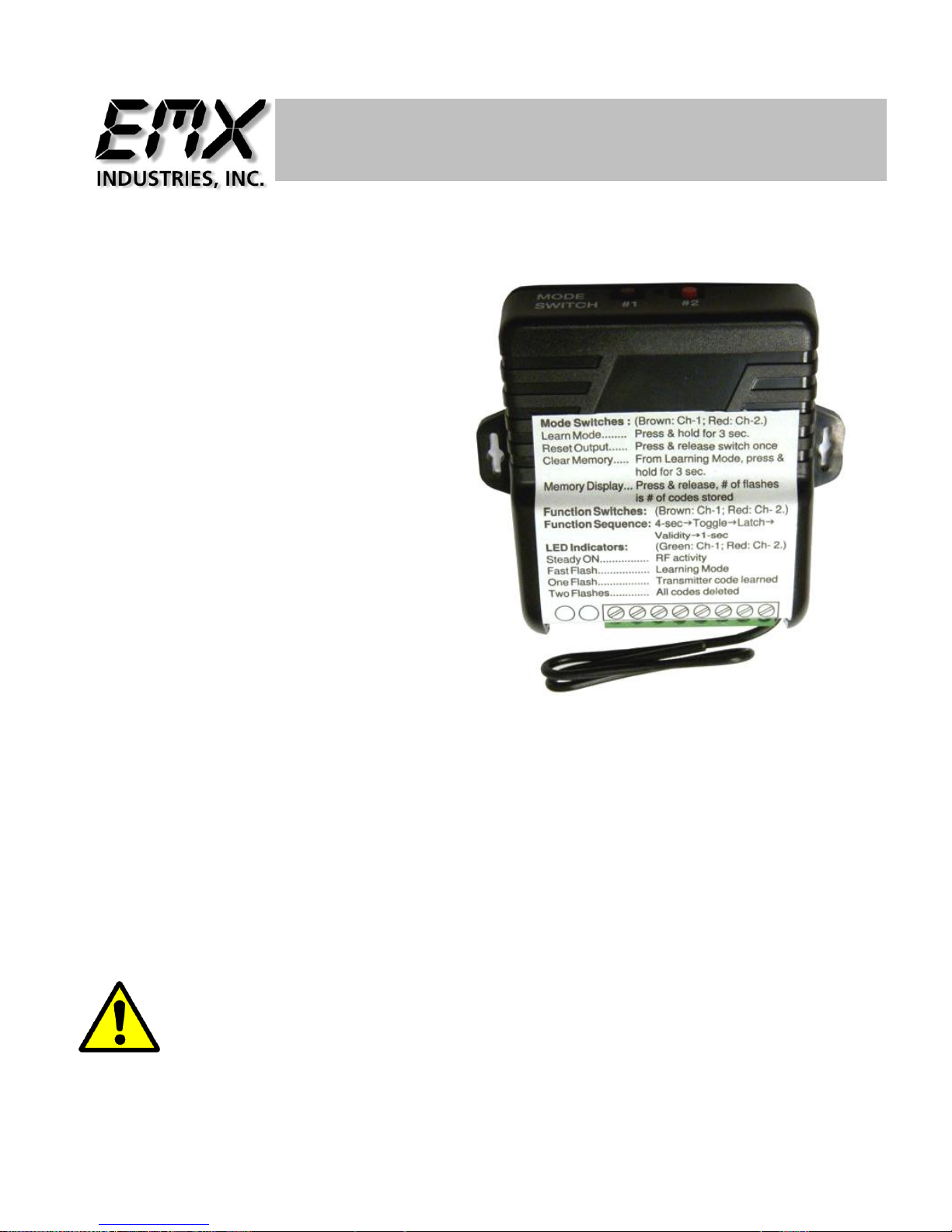
Product Overview
The LR652 wireless receiver meets the growing demand for receivers with multiple and independently
controlled output functions. These RF receivers are compatible with both code hopping and fixed code
transmitters (see page 6 of this manual for a list of compatible transmitters). The receivers can be used to
control a variety of home automation devices such as garage door openers, lights, motorized gates, lifts, or
other devices remotely.
Installation Notes
1. Mount the receiver out of sight in a location where it is not exposed to weather or moisture and where
it is not surrounded by metal. Metal will block the RF signal, resulting in reduced range.
2. For best results pull the wire antenna as long and straight as possible. If the receiver receives
interference from local RF activity (e.g., airport or military base.) the antenna wire can be folded to
reduce interference.
IMPORTANT: DO NOT CUT THE ANTENNA WIRE
Technical Specifications
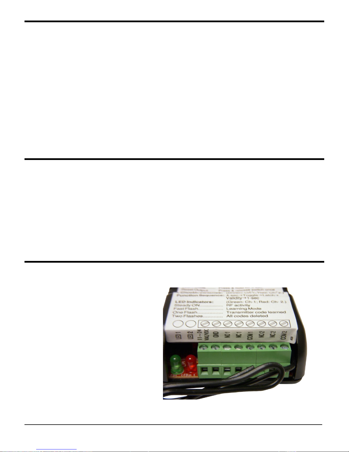
Connections
#1 Power + 11 – 24 V AC/DC
#2 Power - 11 – 24V AC/DC
#3 Normally Open relay 1 contact
#4 Normally Closed relay 1 contact
#5 Common relay 1 contact
#6 Normally Open relay 2 contact 1 2 3 4 5 6 7 8
#7 Normally Closed relay 2 contact
#8 Common relay 2 contact
LR 652 Operating Instructions 2
Document no. REV 1.2 Date 09/04/2013
The LED will flash for a maximum of 15 seconds.
If no transmitter button is pressed during this time
the receiver will exit programming mode and the
LED will turn off.
Only fifteen individual codes may be “learned“ by
the LR-650. If you enter a sixteenth code the first
code entered will be removed from memory.
If the code being learned is already in the system
the LED will turn on steady and then begin flashing
again. The code will not be learned the second
time.
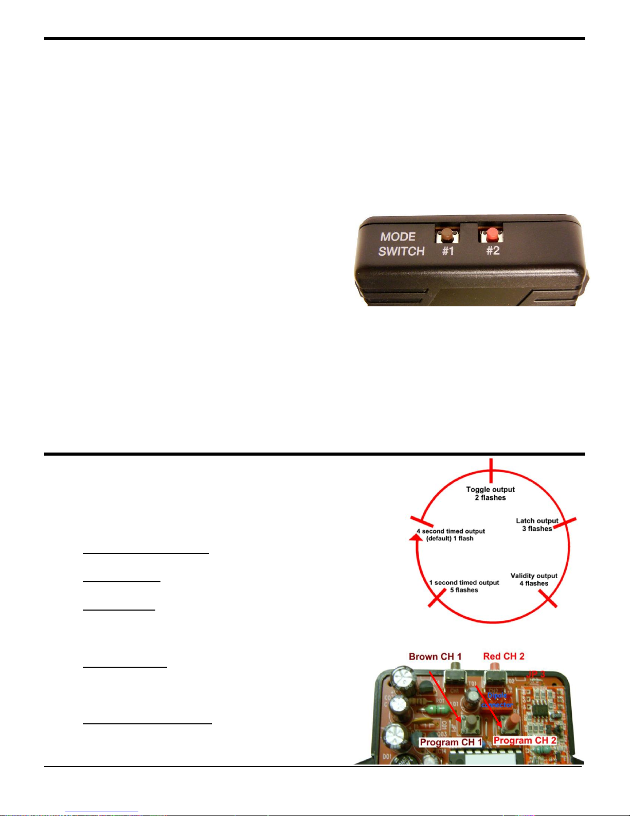
The LR-650 has five output functions that may be programmed by
the use of the program switch (indicated by the arrows) in the
picture bottom right. Functions may be programmed based on user
needs:
1. 4 Second Timed Output (default). When the transmitter
button is pressed the relay will energize for 4 seconds.
2. Toggle Output Press the transmitter button once and the
relay turns on. Press again and the relay turns off.
3. Latch Output Press the transmitter button one and the relay
stays on even if another programmed transmitter button is
pressed. The relay may only be turned off by pressing the
Mode button (referenced above).
4. Validity Output The relay will turn on for as long as the
transmitter button is pressed. Note: Due to interference or
low transmitter battery power the signal may be lost and
allow the relay to turn off.
5. 1 Second Timed Output When the transmitter button is
pressed the relay will turn on for 1 second.
Instructions on next page
Programming Remotes
Each receiver channel can learn the codes of up to 15 different transmitters on a first-in, first-out basis.
Below is the procedure for teaching a new transmitter button.
1. Press the channel mode switch for 3 seconds or more. The channel LED will start to flash quickly to
indicate that it is in programming mode.
2. While the LED is flashing press the button of the transmitter to be learned one time. The receiver
LED will flash once to indicate the code has been successfully learned. After the transmitter has been
learned the receiver will automatically exit programming mode. To add additional transmitters repeat
step 1 and 2 as necessary. See picture below for example.
Note:
3. To clear all codes from the LR-650 memory press the mode switch for 3 seconds or until the LED
flashes. Release, then press the mode switch for 3 seconds or more and the LED will stop flashing.
The LED will then flash twice to indicate that all codes have been deleted.
4. To Display how many codes are in the LR-650 memory, press and release the mode switch once. The
LED will flash once for each code in memory (e.g. 10 flashes equal 10 codes)
Note: Follow steps 1 – 4 as needed for Channel #2
Programming Relay Functions
LR 652 Operating Instructions 3
Document no. REV 1.2 Date 09/04/2013
 Loading...