

EMX Industries, Inc. CS303-L Operating Instructions Manual
CarSense 303
O P E R A T ING I N S T R U C T I O N S
4564 Johnston Parkway, Cleveland, Ohio 44128
P.
Sales Inquiries:
Technical Support:
L O G I C I N T E R F A C E
-
L
TM
800 426 9912 F. 216 518 9884
salessupport@emxinc.com
technical@emxinc.com
www.emxinc.com

Contents
Cautions and Warnings
Product Overview
Specific ations
Operat ion
Controls and Indicators
2
2
3
3
6
Connec tions
Troubleshooting
Instal l ation
Ordering Information
7
7
8
8
CarSense 303-L™ Operating Instructions 1
Document no. 10310404 Revision 1.6 5-30-17

Cautions and Warnings
CE REQUIREMENT: Use CE rated power supply for CE compliance providing
suppression as specified by EN61000-4-5.
Not to be used in safety applications.
IMPORTANT:
This product is an accessory or part of a system. Always read and follow the
manufacturer’s instructions for the equipment before connecting this product. Comply
with all applicable codes and safety regulations. Failure to do so may result in damage,
injury, or death.
WARNING:
DO NOT INSTALL THE SENSOR DIRECTLY INTO HOT ASPHALT, see installation section
WARNING:
Always use photoelectric protection when using the CS303 as a closing
detector on a parking arm operator to prevent accidental closing on a car.
Product Overview
The CarSense 303 Logic Interface (CS303-L) works with CarSense 303 Direct Burial (CS303DB) or CarSense 303 Flat Pack (CS303-FP) magnetoresistive sensors. Once the sensors
have been programmed using the CarSense 303 Controller (CS303-C-1), the sensors store
the settings and can operate independent of the controller.
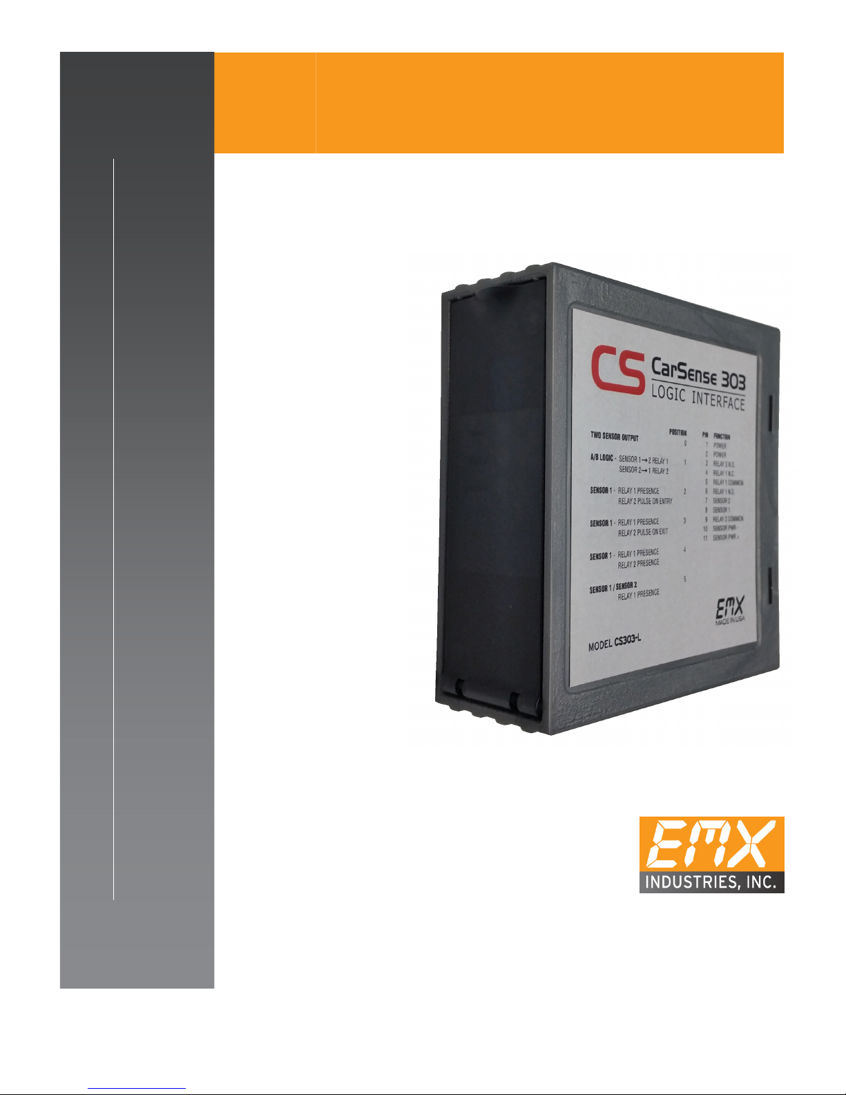
The Logic Interface allows one or two sensors to be connected and provides 6 different
logic functions and two sets of relay outputs, one form A and one form C.
These functions include:
• AB Directional Logic
• Pulse on Entry
• Pulse on Exit
• Common Relay operation
• Discrete Relay operation
• Dual Relay operation
For more information regarding these functions and how they work, see page 4
CarSense 303-L™ Operating Instructions 2
Document no. 10310404 Revision 1.6 5-30-17

Power
Specifications
Specifications
Power Indicator Green LED
Detect Indicator 2x Red LEDs
Configuration Selector 10 position rotary switch
Outputs
Relay 1: SPDT (form C)
Relay 2: SPST (form A)
Maximum Output Ratings 1A @ 24 VDC/120 VAC
-40o C…82o C (-40o F…180o F)
Operating Environment
0…95% relative humidity
Housing Material ABS
Enclosure IP30
(see Cautions and Warnings)
Operating Current
(Standby/Detect)
One sensor connected: 22/35mA
Two sensors connected: 33/60mA
12-30 VDC or 24 VAC
Supply Protection Circuitry Reverse polarity and fuse protected
Dimensions 73mm (2.9”) x 38mm (1.2”) x 78mm (3.1”)
Weight 0.25 lbs. (113 g)
Connector 11 pin male connector (JEDEC B11-88)
NOTE: Refer to CarSense 303 Operating Instructions for operation and installation of
controller and sensor.
Operation
Power Up
Upon power up the detector initializes: all three LEDs will flash on, then off. The green
LED indicates that the detector is powered and operational. Relay1 and Relay2 LEDs
indicate when Relay1 or Relay2 is activated, respectively.
Note that the sensor must be installed and programmed using a CS303-C-1 prior to
connection to the CS303-L. The CS303-L only monitors the sensors’ NPN outputs and
cannot be used to change operation settings in the sensor.
CarSense 303-L™ Operating Instructions 3
Document no. 10310404 Revision 1.6 5-30-17
 Loading...