

This product is an accessory or part of a system.
Always read and follow the manufacturer’s
instructions for the equipment you are connecting
this product to. Comply with all applicable codes and safety
regulations. Failure to do so may result in damage, injury or
death!
BBPPEE--550
0
™
Photo Beam with battery
powered Transmitter
Not UL325 compliant
Operating Instructions
Product Overview
The BPE-50 photo beam system uses 12 -24 VDC/AC on
the transmitter and receiver with the transmitter offering the
option of using the two 3.6 Volt batteries for power
(included). Recommended battery replacement is the Varta
ERAA 3V6 2400.
Technical Specifications
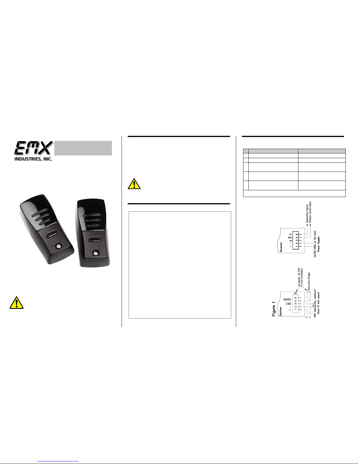
Connections (Fig 1)
Power Supply
12-24 VDC 24 VAC (2-3.6 Volt Lithium
Batteries for transmitter optional
/included)
Expected battery life up to 2 years
approx.
Current Draw
RX = <50mA standby 100mA activated, TX
= < 500uA
Relay Type
2 Form C DPST contact rating .5A @ 24VDC
/ 120VAC
Temperature
-20C – 55C
Wavelength
880 nm
Frequency
High 90 Hz Low 48 Hz (Ext power 787 Hz)
Environmental
IP 65
Detect Indicator
Red LED
Connector
Terminal block
Relay contact
0.5Amp
Housing Material
PA6 30% FG
Size
H 4.4in (112mm) x W 2.05in (52mm) x D
1.3in (33mm)
Range
Up to 50 feet (if TX on 12/24 V 90 feet)
Detection Angle
+/- 5%
Sensitivity
Jumper J1 on receiver
Detection delay
< 30 ms
Reset delay
< 120 ms Transmitter
Receiver
1
Power Positive (+)
Power Positive (+)
2
Power Negative (-)
Power Negative (-)
3
NC Security Contact
(join if not used)
Internal Relay
Normally Open
4
Security edge
(join if not used)
Internal Relay
Common
5
Security edge
(join if not used)
Internal Relay
Normally Closed Output
Terminal connection as viewed from the front, left to right
WARNING … Not to be used for Personnel Protection
Never use product as sensing devices for personnel protection.
Doing so could cause serious injury or death.
These sensors do NOT include the self-checking redundant circuitry
necessary to allow their use in personnel safety applications. A sensor failure or
malfunction can cause either an energized or de-energized sensor output
condition. UL 325 Non-compliant

Both the transmitter and receiver lenses may be aligned
left, right or straight ahead. To align gently pull the lens
stem straight out from mounting position and snap back
into place pointing in the desired direction.
Units should be placed a minimum of 12 – 16 inches
from the floor. Across from and lenses facing each
other. The receiver red detect LED will be on when the
beam is broken or not aligned.
Place the BPE-50 away from heat and electromagnetic
sources for best operation. Mount units a minimum of
12 inches 30 cm from the floor.
Apply power to the units and set jumpers per instruction
on see figures 1 and 2.
Test installation to insure desired and proper operation.
All local and operator manufacturer installation
instructions should be followed.
The BPE-50 transmitter may be hooked up to an edge
sensor for alternative activation operation.
The BPE-50 does not require any special care, but it is
necessary to check condition occasionally to insure they
are operating correctly. (Batteries are still operational if
on battery power)
Recommended battery replacement is the Varta ERAA 3V6
2400.
4564 Johnston Parkway
Cleveland, Ohio 44128
United States of America
WEB http://www.emxinc.com
Technical Support Telephone (216) 834-0761
E-mail technical@emxinc.com
Sales Telephone (216) 518-9888
Fax (216) 518-9884
Email salessupport@emxinc.com
BPE-50 Instructions rev 1.2 06/20/2013
Jumper Configuration (Fig 2)
Lens Alignment (Fig 3)
Installation (Fig 4)
Jumper
ON
OFF
Receiver J1 (Gain)
Normal
High
Transmitter J2
(frequency)
Fast
Slow
Transmitter J3 (Security
edge)
Not
connected
Connected
Jumper Settings for figure 2
When transmitter frequency is set to low battery
life will be increased. The range will be reduced
at this setting. However when the transmitter is
powered by 12/24 VDC or 24 VAC the range will
be maximum regardless of the jumper setting.
 Loading...