


EMX Industries, Inc. Tech support: 216-834-0761 1/7
VMD202_Rev2.0_081319 technical@emxinc.com
VMD202™
Single Piece Vehicle Motion Detector
with Detachable Sensitivity Remote
Instruction Manual
The VMD202 is a compact, single-piece vehicle motion detector that operates by detecting changes in the
earth’s magnetic field that occur near the probe. It has a detection range up to 12 feet at a
minimum speed of 5 mph. The VMD202 will only detect a moving vehicle and will not detect
a stationary vehicle. It may be used as a free exit sensor to allow gates to open and guests to exit without
the use of a key fob or passcode. The VMD202 may also be wired to notify a home automation system or
security system that a vehicle is moving down a driveway. This vehicle motion detector features
a detachable sensitivity remote and is available in 50, 100, or 150 foot lead lengths.
Cautions and Warnings
The VMD202 is designed to detect moving vehicles. It is not suitable for use as a vehicle
presence detector such as a reversing loop for a gate or door.
The VMD202 detects ferrous metals. It will not detect aluminum, but will detect any
moving ferrous metallic object.
The probe must be stationary to function properly.
Specifications
Power
9-41 VDC or 6-29 VAC
Power Indicator
Green LED (remote control only)
Standby Current
0.250 mA
Detection Current
12 mA
Range Sensitivity
12 ft @ 5 mph min. speed
Sensitivity Adjustment
10 settings
Output Time
5 seconds
Surge Protection
Probe input circuitry protected by surge suppressors
Relay Output Configuration
Form C (SPDT)
Relay Contact Rating
1 A @ 24 VDC / 1 A @ 120 VAC
Operating Temperature
-40˚C to 82˚C (-40˚to 180˚F) 0 to 95% relative humidity
Remote Housing Material
ABS plastic
Remote Dimensions (L x W x H)
3.0” (76 mm) x 0.9” (22 mm) x 2.75” (70 mm)
Remote Weight
0.15 lbs (68 g)
Probe Housing Material
PVC watertight
Probe Dimensions (L x Dia.)
24” (610 mm) x 1” (25 mm)
Probe Cable
5-wire, direct burial
EMX Industries, Inc. Tech support: 216-834-0761 2/7
VMD202_Rev2.0_081319 technical@emxinc.com
Ordering Information
• VMD202-HAR VMD202 harness, 4 pin male connector (included)
• VMD202-JMPR VMD202 jumper, 4 pin female connector (included)
• VMD202-5-50 VMD202 50’ lead-in wire
• VMD202-5-100 VMD202 100’ lead-in wire
• VMD202-5-150 VMD202 150’ lead-in wire
• VMD202-5-XX VMD202 (enter required length in ft) lead-in wire
• VMD202-R VMD202 sensitivity remote control
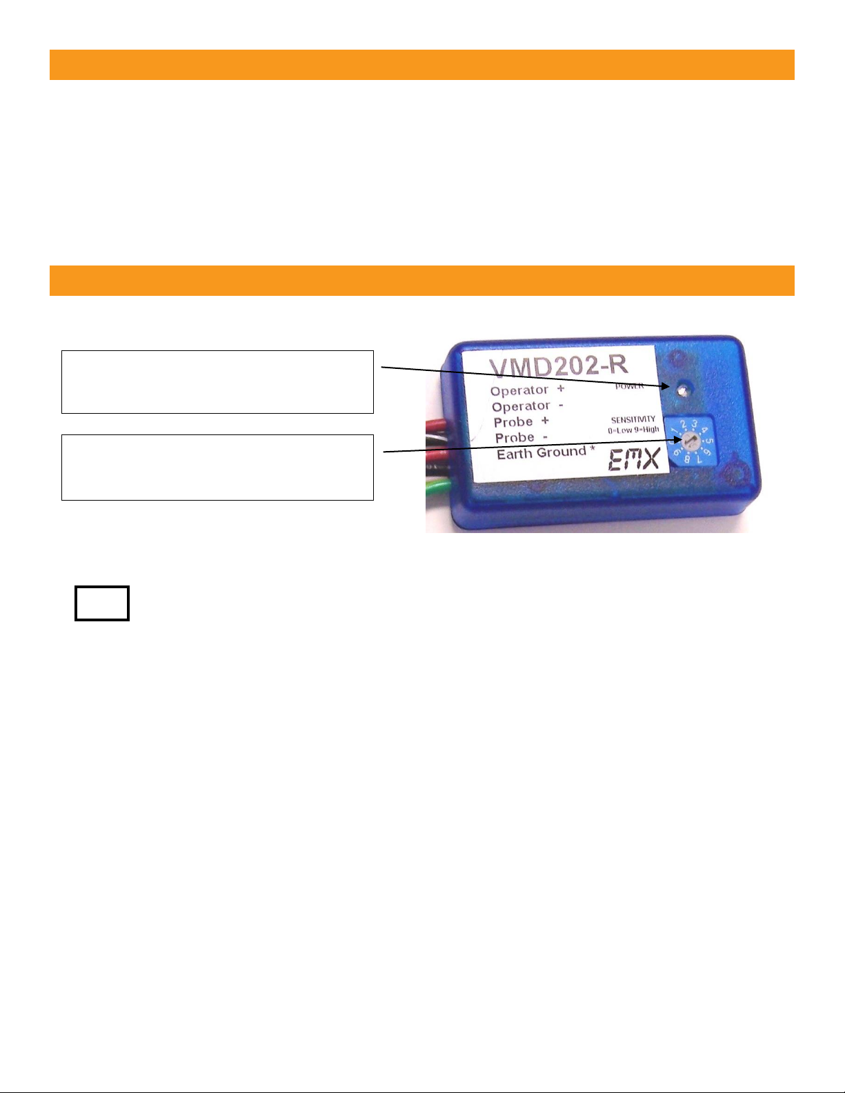
Controls and Indicators
Sensitivity is a function of speed and mass. The slower a vehicle is moving, the closer
it must pass the probe to trigger the detector.
Power LED
Green LED flashes when power
is applied
Sensitivity Adjustment
10 positions
Minimum 0 to maximum 9
EMX Industries, Inc. Tech support: 216-834-0761 3/7
VMD202_Rev2.0_081319 technical@emxinc.com
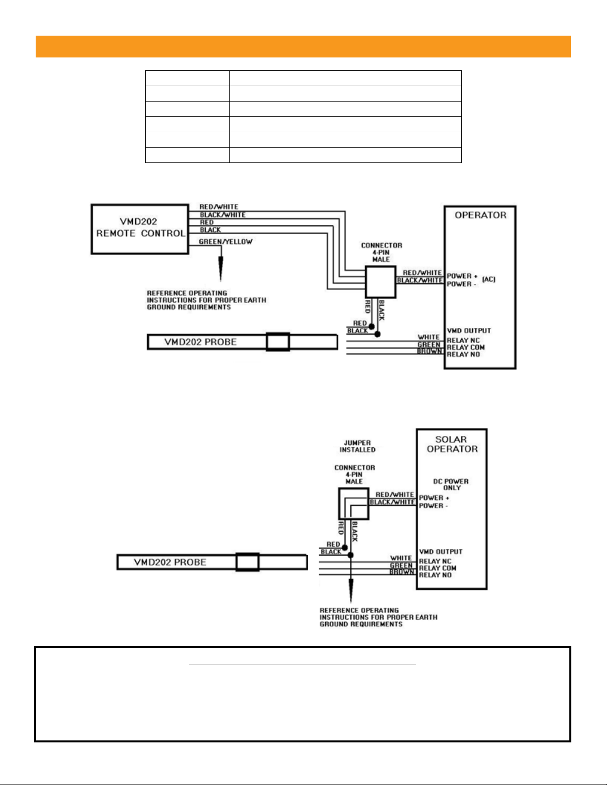
Wiring Connections
Standard Applications
Solar
Applications
The jumper is installed and the remote control is removed to minimize power consumption.
Wire Color
Description
Red/White
Power + (9-41 VDC or 6-29 VAC)
Black/White
Power – (9-41 VDC or 6-29 VAC)
Green
Relay – COM (common contact)
White
Relay – NC (normally closed contact)
Brown
Relay – NO (normally open contact)
IMPORTANT: EARTH GROUND CONNECTION
The VMD202 contains transient protection devices to guard the sensitive electronic circuitry from damage
and false triggering due to electrical transients caused by lightning or other sources. Always provide a good
earth ground connection to the green wire of the VMD202 remote control in standard applications or the
black wire of the VMD202 probe in solar applications. An 8’ copper rod or metal cold-water pipe provides a
sufficient earth ground connection.

EMX Industries, Inc. Tech support: 216-834-0761 4/7
VMD202_Rev2.0_081319 technical@emxinc.com
Read the following list of tips prior to beginning the installation process.
This will save significant time in the long run.
• The detector’s sensitivity is a function of speed and mass. The detection distance for a moving,
average size car or truck is approximately 12 feet at a speed of 5 mph. At higher speeds, detection
distance can exceed 12 feet as noted below.
• The detector is sensitive to minute changes in the magnetic field around the probe.
Power lines, transformers, and other electrical devices located in the vicinity of the probe
that produce transients could cause disturbances in the magnetic field that may result in
triggering the detector. Avoid installation of the probe near these devices.
• Do not install the probe or lead wire near or parallel to:
• Low voltage lighting wires or in-ground power lines
• Telephone lines or intercom systems
• Electric motors or control relays
• Overhead power lines, transformers or underground power lines
• Cell phone towers, TV towers or communications links
• Moving metal flagpoles, fences, gates or horses with metal shoes
Installation
Size of Moving Vehicle
Speed
Detection Distance
Average size car or truck
5 mph min.
Up to 12’
Average size car or truck
10-50 mph
Greater than 12’
Large truck or semi-truck
Over 50 mph
Greater than 40’
Train
Any
100’
Typical connection to operator
with VMD202 remote control installed.
Typical connection to operator
with VMD202 remote control removed.
Note the bypass jumper in the connector.

EMX Industries, Inc. Tech support: 216-834-0761 5/7
VMD202_Rev2.0_081319 technical@emxinc.com
• Do not mount on any moving surface, such as bridges or walkways that may vibrate under traffic.
The probe must always be installed in such a way that it remains completely motionless.
Any movement will cause the probe to trigger.
• Probes are available in various cable lengths, when possible select the appropriate cable length
for the installation. If it is necessary to extend the cable length (maximum 900’), use a
high-quality lead-in cable suitable for direct burial and a high quality, watertight cable splice
to prevent moisture from entering the cable causing false triggering. Lead-in wire is available from
EMX.
• The VMD202 harness is supplied attached to the VMD202 probe wires. The harness may be cut
loose and the lead shortened to the desired length. Re-attach the harness with wire nuts and tape
to prevent shorts.
• When there is a high incidence of damage from burrowing animals or other potential damaging
activities, it is recommended that the cable be placed in plastic conduit (1.5” internal diameter).
Damage to the cable jacket may allow moisture to enter the cable causing false triggering. When
placing the probe in plastic conduit, use foam or tape to assure that the probe
does not move or vibrate. It is recommended that the conduit be sealed to prevent water from
collecting in it.
Installation instructions continued on next page.

EMX Industries, Inc. Tech support: 216-834-0761 6/7
VMD202_Rev2.0_081319 technical@emxinc.com
Installation Methods
Adjacent to Roadway (Recommended Method)
In a Roadway
1. Temporarily place the probe parallel to the
roadway (driveway) in the desired location.
1. Position the probe in the center of the
roadway, perpendicular to the direction of
traffic. The probe should be located at a
minimum of 2” deep in concrete or asphalt.
• If installing the probe prior to paving a hot
asphalt roadway, the VMD202 and its lead
cable need to be insulated. A common
method to do this would be to dig a small
trench and bury the probe and lead cable in
4” of sand prior to paving. (DO NOT APPLY
HOT ASPHAULT DIRECTLY AGAINST
PROBE AND LEAD CABLE!)
• If installing the probe in concrete, make sure
it is installed above the rebar.
• The probe may be positioned prior to paving
or a cut may be made in the finished
pavement for installation.
2. Connect the power, VMD202 remote control, output relay contact and earth ground to the
intended equipment. (Reference EARTH GROUND CONNECTION in Wiring Connections.)
DO NOT EXCEED 41 VDC or 29 VAC.
3. Apply power and allow 5 minutes of warm-up for system stabilization.
4. Set sensitivity to 0.
5. Drive a vehicle at a minimum speed of 5 mph passed the probe and to the far side of the roadway.
6. Repeat step 5 while gradually increasing the sensitivity until the system detects the vehicle.
• A higher sensitivity setting than required to detect the vehicle makes the system more
vulnerable to triggering from unintended sources such as movement of other objects,
including bicycles, horses, small vehicles, metal in shoes or other electrical disturbances.
• When the detector is set to maximum sensitivity (full counterclockwise on the sensitivity
adjustment) detection distance is approximately 12 feet at a speed of 5 mph. At higher
speeds, 10-15 mph, detection distance can exceed 12 feet.
7. Bury the probe at this location approximately
8-12” deep for typical applications. Repeat the
previous sensitivity check (step 4-5) to verify
proper operation. Installation adjacent
to roadway complete.
7. Installation in roadway complete.
For instances of high pedestrian traffic, heavy animals or heavy vehicles, bury the probe
24” deep to prevent false triggering in either installation method.
TIP:
TIP:
TIP:

EMX Industries, Inc. Tech support: 216-834-0761 7/7
VMD202_Rev2.0_081319 technical@emxinc.com
EMX Industries, Inc. products have a warranty against defects in materials and workmanship for a period
of two years from date of sale to our customer.
Troubleshooting
Symptom
Possible Cause
Solution
False triggering
Electrical disturbances
Damaged probe cable
Moisture in probe cable
Movement in the probe’s
environment
Dirty or noisy power supply
Lightning
1. Verify that the earth ground connection to the
VMD202 is secure. If the connection is not secure,
reconnect both the VMD202 and the
earth ground and retest the system.
2. Disconnect the relay wires (green, white, brown)
and see if the false triggering continues. If the false
triggering stops, check the probe as outlined below
in step 3. If the false triggering continues,
disconnect the power and temporarily connect a
9 or 12V battery to the VMD202 and reconnect the
probe. Wait 5 minutes for the system to stabilize. If
the false triggering stops, consider using a separate
power supply for the VMD202 such as a 120 VAC to
12 VDC power converter (min. 100 ma). Reconnect
the probe and retest the system.
3. Inspect the area around the probe to see if any
ferrous metal objects may be subject to any
movement. These may include fences, flagpoles,
signs, etc. Other possible causes are electrical
power lines, electric motors, invisible dog fences,
low voltage lighting and high-power lighting.
No output
Bad wire connection
Failed relay
1. Disconnect the output contacts from the operator.
2. Connect a digital multimeter, set to read ohms, to
the COM and NO contacts. The meter should read
open (infinity).
3. Move a metal tool over the length of the probe.
Verify that the meter reads less than 10 ohms. If the
meter reads more than 10 ohms, the VMD202 is
defective.
No detection
Minimum 5 mph
Bad wire connection
Faulty power connection
Failed relay
1. Verify that the VMD202 remote control’s
green LED is on. If not, check the supply voltage
using a digital multimeter. Verify the voltage is
9-41VDC or 6-29 VAC.
2. If voltage is present and there is still no detection,
the VMD202 is defective.
Warranty
 Loading...