

EMX Industries, Inc. Tech support: 216-834-0761 1/7
ULT-MVP_Rev2.0_082319 technical@emxinc.com
ULT-MVP
™
Multi-Voltage Vehicle Loop Detector
Instruction Manual
The ULT-MVP vehicle loop detector allows for detection of metallic objects entering the field around an
induction loop. This detector automatically adjusts from 12 VDC up to 240 VAC which eliminates
the installer’s need to match available power to an appropriately rated vehicle detector.
The ULTRAMETER™ display feature makes set-up easy by displaying the optimum sensitivity setting
required to detect a vehicle positioned near the loop. Ten sensitivity settings allow for fine adjustment
of the detection level. The ULT-MVP provides relay contact outputs indicating vehicle presence and a
second set of relay contact outputs providing auxiliary functions. The second output can be used for
loop fault or pulse on entry/pulse on exit, or the EMX exclusive feature, Detect-on-Stop™ (DOS®).
The ULT-MVP features automatic sensitivity boost (ASB), delay, fail-safe/fail-secure and
infinite or normal (5 minute) presence. Four frequency settings provide flexibility in preventing crosstalk
in multi-loop applications.
Cautions and Warnings
This product is an accessory or part of a system. Install the ULT-MVP according to
instructions from the gate or door operator manufacturer. Comply with all applicable
codes and safety regulations.
Specifications
Power
12-60 VDC or 12-240 VAC (48-62 Hz)
Operating Current (Standby/Detect)
25 mA/50 mA
Loop Frequency
4 settings (low, med-low, med-hi, high)
Loop Inductance
20-2000 µH (Q factor ≥ 5)
Surge Protection
Loop circuitry protected by surge suppressors
Presence Relay
SPDT relay contacts (form C)
Output B Relay
SPDT relay contact (form C)
Contact Rating (Resistive Load)
2 A @ 30 VDC, 0.5 A @ 125 VAC
Operating Temperature
-40º to 82ºC (-40º to 180ºF) 0 to 95% relative humidity
Environmental Rating
IP30
Connector
11 pin male connector (JEDEC B11-88)
compatible with DIN rail mount socket or wire harness
Dimensions (L x W x H)
73 mm (2.9”) x 38 mm (1.2”) x 78 mm (3.1”)
TM

EMX Industries, Inc. Tech support: 216-834-0761 2/7
ULT-MVP_Rev2.0_082319 technical@emxinc.com
Ordering Information
• ULT-MVP-U Multi-voltage vehicle loop detector, US wiring
• ULT-MVP-E Multi-voltage vehicle loop detector, EU wiring
• HAR-11 11 position harness, 3’ of wire
• LD-11 11 pin DIN rail socket, black, wide base
• LD-11B 11 pin DIN rail socket, black, narrow base
• PR-XX Lite preformed loop (XX – specify size)
• TSTL Test loop, troubleshooting tool
Wiring Connections
* Contact rating: 2A @ 30 VDC, 0.5A @ 125 VAC
**Output B configurable for Pulse on Entry, Pulse on Exit, Detect-On-Stop™ or Loop Fault modes
Description
US DIN Rail Socket
(for ULT-MVP-U)
EU DIN Rail Socket
(for ULT-MVP-E)
Harness
Wire
Power (12-240 VDC/AC)
1
1
Black
Power (12-240 VDC/AC)
2
2
White
Output B – NO* (normally open contact)
3
3
Orange
Shield – Earth Ground
4
9
Green
Presence – COM* (common contact)
5
6
Yellow
Presence – NO* (normally open contact)
6
5
Blue
Loop Connection
7
7
Gray
Loop Connection
8
8
Brown
Output B – COM (common contact)
9
4
Red
Presence – NC* (normally closed contact)
10
10
Pink
Output B – NC** (normally closed contact)
11
11
Violet
US DIN Rail Socket OR 11 Wire Harness

EMX Industries, Inc. Tech support: 216-834-0761 3/7
ULT-MVP_Rev2.0_082319 technical@emxinc.com
Settings & Display
1. Frequency Count / Reset Button
Press and release the frequency count button and count the number of
flashes on the red LED. Each flash represents 10 kHz. Following a frequency
count cycle, the detector re-initializes.
2. Sensitivity Setting
The 10-position rotary switch allows for adjustment of detection level.
The sensitivity level increases from position 0 (lowest setting) through
9 (highest setting). Typical applications require a setting of 3 or 4.
The rotary adjustment must be set to a specific/whole number.
There are no half settings.
3. Detect / Frequency Count (Red LED)
Presence Detected
on
No Presence
off
Frequency Count
flashing
4. Power / Loop Fault Indicator (Green LED)
Normal Operation
on
Upon power up, the detector
initializes by automatically tuning
to the loop. The green LED
indicates that the detector is
powered and operational.
Shorted or Open Loop
fast flash
Previous Loop Fault
flashes once
intermittently
5. ULTRAMETERTM Display
The display shows the sensitivity setting required to detect a vehicle
near the loop. To use this feature, observe the display while a vehicle
is moving into position near the loop, note the number displayed, then adjust
the sensitivity setting to the displayed position. The display will adjust
from 9 for a weak signal to 0 for a very strong signal. During normal operation,
when a vehicle is not on or near the loop, the display is blank. The effects of
cross-traffic interference can be observed on the display when the
sensing area is vacant.
6. DIP Switch
The DIP switch settings are explained on the next page.
3
4
6 5 1
2
EMX Industries, Inc. Tech support: 216-834-0761 4/7
ULT-MVP_Rev2.0_082319 technical@emxinc.com
Automatic
Sensitivity
Boost
DIP Switch 1
The Automatic Sensitivity Boost causes the sensitivity
to increase following initial detection. This feature is useful
to prevent dropout when detecting high-bed vehicles.
The sensitivity returns to its normal setting after the vehicle exits
the loop. The decimal point on the ULTRAMETERTM display
indicates ASB is on.
ASB Enabled
on
ASB Disabled
off
Presence
DIP Switch 2
Infinite presence mode causes the output to remain in detect
as long as the vehicle remains on the loop. Normal presence
mode causes the output to reset after 5 minutes. Do not use
Normal presence mode for reversing loop applications.
Normal
on
Infinite
off
Delay
DIP Switch 3
Turning on the delay setting provides a 2 second delay before
activating the relay after the sensitivity threshold is met.
Do not use the Delay mode in reversing loop applications.
Delay On
on
Delay Off
off
Output B
DIP Switch
The Output B relay is configurable for four possible modes.
In Pulse on Entry/Exit mode, Output B will be activated
for approximately 500ms when a vehicle is entering or exiting
the detection zone. The Detect-On-Stop™ (DOS®) feature
requires that a vehicle must come to a complete stop over the
loop for a minimum of 1-2 seconds before Output B activates.
Do not use DOS® feature for reversing loop applications.
In Loop Fault mode, Output B will trigger if a loop fault occurs.
Mode
4
5
Pulse on Entry
on
on
Pulse on Exit
on
off
DOS®
off
on
Loop Fault
off
off
Fail Safe / Secure
DIP Switch 6
The Fail Safe setting causes the ULT-MVP to activate
the presence output in the event of a loop failure.
The Fail Secure setting will cause the ULT-MVP not to activate
the presence output in the event of a loop failure.
Do not use Fail Secure for reversing loop applications.
Fail Safe
on
Fail Secure
off
Frequency Settings
DIP Switch
DIP switches 7 and 8 are used to assign the loop operation
frequency. The primary purpose of the frequency setting
is to allow the installer the ability to set different operating
frequencies for multi-loop installations and is recommended
to prevent crosstalk/interference from multiple loops.
7
8
Low
on
on
Medium Low
on
off
Medium High
off
on
High
off
off
EMX Industries, Inc. Tech support: 216-834-0761 5/7
ULT-MVP_Rev2.0_082319 technical@emxinc.com
Loop Installation
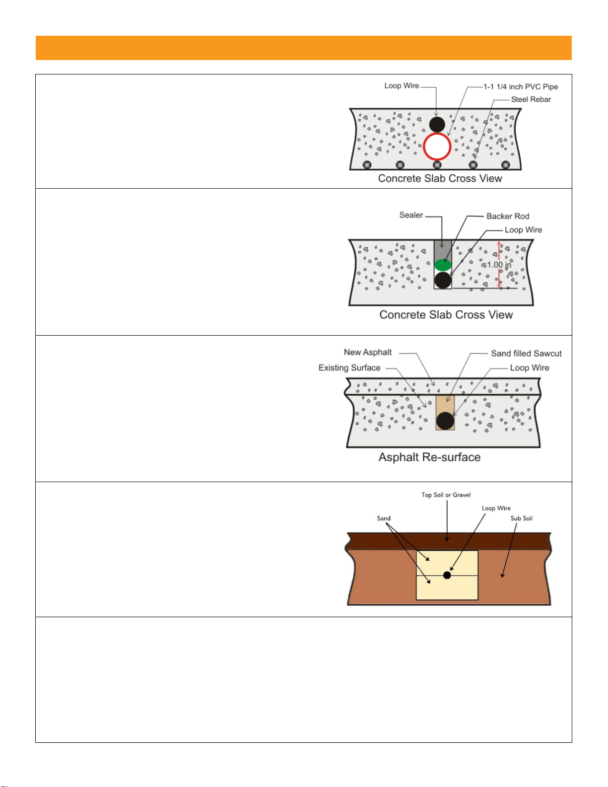
NEW SLAB POUR
Ty-wrap 1-1/4” PVC pipe to the top of the rebar in the
size and configuration of the loop (ex. 4’ x 8’).
Then ty-wrap the loop to the top of the PVC frame.
This stabilizes the loop during the pour and separates
it from the rebar.
SAW CUT EXISTING SURFACE
Cut 1” deep into the existing surface, place a 45° cut at
the corners to prevent sharp edges from damaging the
loop wire. Notch out for the “T” connection where the
lead wire connects to the loop. Remove all debris from
the finished cut with compressed air. Place the loop
into the saw cut. Place backer material into the
saw cut over the loop wire and pack tightly. Place a
high-quality sealer over the saw cut to seal the surface.
RESURFACE ASPHALT
Saw cut the existing surface ¾” deep and place a 45°
cut at the corners to prevent sharp edges from
damaging the loop wire. Remove all debris from the
finished cut with compressed air. Place sand over
the loop wire to the surface and pack tightly.
Lay new asphalt.
GRAVEL OR SOIL INSTALLATION
While this is not a recommended installation for
most loops, it has been used successfully with
proper preparation. Remove gravel or top soil until
reaching a stable base. Dig ~ 6-8” deep by ~ 6-8” wide.
Fill halfway with sand and pack tightly. Place the loop
into the trench and finish filling to level with sand.
Pack tightly and replace gravel or soil over top.
GENERAL INSTALLATION GUIDELINES
• Use EMX lite preformed loops for quick, reliable installations.
• It is not recommended to install a loop near power lines (overhead or underground) or low voltage lighting.
If necessary near these power sources, place at a 45° angle. Make the loop shape a diamond, not a square.
• Never install a loop near inductive heaters.
• If using a non-preformed loop, lead-in wire (wire from loop to detector) must be twisted a minimum of
6 turns per foot to avoid the effects of noise or other interference.
• Detection height is approximately 70% of the shortest side of the loop.
For example: detection height for a 4’ x 8’ loop = 48” x .7 = 33.6”
EMX Industries, Inc. Tech support: 216-834-0761 6/7
ULT-MVP_Rev2.0_082319 technical@emxinc.com
1. Connect the 11 pin DIN rail socket or wire harness to the ULT-MVP and connect pins 1 and 2
(white and black wire) on the socket/harness to the appropriate power source.
Pin 4 (green wire) must be connected to earth ground for effective surge protection.
2. Connect the loop wires to pins 7 and 8 (gray and brown wire).
3. Connect the operator wires to the socket/harness according to preferences and instructions
provided by the operator manufacturer (see Wiring Connections).
4. Configure the DIP switches according to preferences. Refer to Settings & Display for
more information.
5. If using multiple loops or suspect crosstalk/interference from the environment, perform a
frequency count on each detector to confirm that the operation frequencies are different.
• Press the FREQUENCY COUNT / RESET button and count the number of flashes of the
red LED. Each flash represents 10kHZ. Counts from 3 to 13 confirm that the detector is
tuned to a loop.
• If multiple loops and detectors are utilizing the same or very similar frequency,
configure DIP switches 7 and 8 on one of the devices. For example: Move one ULT-MVP
to the low frequency setting and the second ULT-MVP to the high frequency setting.
6. Press the FREQUENCY COUNT / RESET button to re-initialize the detector and program the
DIP switch settings.
7. Adjust the sensitivity setting to desired level to assure detection of all vehicle traffic.
• To test the sensitivity, without moving the sensing loop, drive a vehicle near the loop.
When the vehicle is first detected by the loop, “9” will be displayed on the ULTRAMETERTM
display. Position the vehicle over the loop where the detection point is desired, take note
of the number displayed on the ULTRAMETERTM and change the sensitivity setting
(10-position rotary switch) to match that number.
• Move the test vehicle away from the loop to remove it from the detection zone
(ULTRAMETER™ display should be blank).
• Press the FREQUENCY COUNT / RESET button on the ULT-MVP.
• Retest the product by moving the vehicle into and out of the detection zone to make sure
the setup and location are working as intended.
8. Press the FREQUENCY COUNT BUTTON / RESET button to calibrate the ULT-MVP to the loop.
Installation
TIP:

EMX Industries, Inc. Tech support: 216-834-0761 7/7
ULT-MVP_Rev2.0_082319 technical@emxinc.com
Warranty
EMX Industries, Inc. products have a warranty against defects in materials and workmanship for a period
of two years from date of sale to our customer.
Installation
Symptom
Possible Cause
Solution
Green LED not on
No power
Check the power supplied to the ULT-MVP on pins 1 and 2
(white and black wire). Voltage should read between
12-240 VDC/AC.
Green LED
fast flash
Loop wire shorted or open
1. Check the loop resistance with a multimeter to confirm
a reading between 0.5 ohms and 5 ohms.
If reading is outside of this range, replace the loop.
The reading should be steady.
2. Check loop connections to terminals.
3. Press the FREQUENCY COUNT / RESET button.
Green LED
flashes once
intermittently
Loop wire was previously
shorted or open
1. Check the loop resistance with a multimeter
to confirm a reading between 0.5 ohms and 5 ohms.
If reading is outside of this range, replace the loop.
The reading should be steady.
2. Press the FREQUENCY COUNT / RESET button.
Red LED
on constantly
(stuck in detection
mode)
Faulty loop
Poorly crimped connection
or loose connection
Perform a megger test from loop lead to ground, it should be
more than 100 megaohms.
Check loop connections to terminals. Verify splices are properly
soldered and sealed against moisture.
Observe ULTRAMETER™ display. The level indicated on the
display indicates residual frequency shift from vacant loop
to vehicle presence. Press the FREQUENCY COUNT / RESET
button to re-initialize the detector.
Detector detects
intermittently
when no vehicle is
on the loop
Faulty loop
Poorly crimped connection
or loose connection
Cross-talk between
multiple loop detectors
Loop not securely installed
to prevent movement of
loop in pavement.
Perform a megger test from loop lead to ground, it should be
more than 100 megaohms.
Check loop connections to terminals. Verify splices are properly
soldered and sealed against moisture.
Set multiple loops to different frequencies.
Verify that loop is securely installed in pavement and that site
is in good condition preventing movement of loop wires.
No detection
Loop wire shorted or open
Loop sensitivity set too low
1. Check the loop resistance with a multimeter
to confirm a reading between 0.5 ohms and 5 ohms.
If reading is outside of this range, replace the loop.
The reading should be steady.
2. With a vehicle on the loop, observe the ULTRAMETER™
display. Set the sensitivity to the level indicated.
 Loading...