

EMX Industries, Inc. Tech support: 216-834-0761 1/7
MVP D-TEK_Rev2.0_081319 technical@emxinc.com
MVP D-TEK™
Multi-Voltage Vehicle Loop Detector
Instruction Manual
The MVP D-TEK vehicle loop detector allows for detection of metallic objects entering the field formed
around an induction loop. This detector automatically adjusts to input power from 12 VDC up to 240 VAC
which eliminates the installer’s need to match available power to an appropriately rated vehicle detector.
The MVP D-TEK is made from anodized aluminum and all switches have gold plated contacts that are sealed
for protection. It features full loop diagnostic with frequency counter, 10 sensitivity settings, delay mode,
extend mode, fail safe/fail secure mode, automatic sensitivity boost, pulse and presence operating modes
and two output relays.
Cautions and Warnings
This product is an accessory or part of a system. Install the MVP D-TEK according to
instructions from the gate or door operator manufacturer. Comply with all applicable
codes and safety regulations.
• MVP D-TEK Multi-voltage vehicle loop detector (included)
• HAR-11 11 position harness, 3’ of wire
• LD-11 11 pin DIN rail socket, black, wide base
• LD-11B 11 pin DIN rail socket, black, narrow base
• PR-XX Lite preformed loop (XX – specify size)
• TSTL Test loop, troubleshooting tool
Specifications
Power
12-60 VDC or 12-240 VAC (48-62 Hz)
Draw Current
19.2 mA
Loop Frequency
3 settings (low, medium, high)
Loop Induction
20-2000 μH (Q factor ≥ 5)
Surge Protection
MOV, neon and silicon protection devices
Relay Contact Rating
2 DPST 1A @ 30 VDC
Operating Temperature
-40º to 180ºF (-40º to 82ºC)
Housing Material
Anodized aluminum
Connector
11 pin male connector (JEDEC B11-88)
compatible with DIN rail mount socket or wire harness
Dimensions (L x W x H)
3.25” (83 mm) x 2.56” (40 mm) x 3.65” (90 mm)
Ordering Information
TM

EMX Industries, Inc. Tech support: 216-834-0761 2/7
MVP D-TEK_Rev2.0_081319 technical@emxinc.com
Wiring Connections
Connector Pin
Harness
Description
1
White
Power (12-240 VDC/AC)
2
Black
Power (12-240 VDC/AC)
3
Orange
Relay 2 – NO (normally open contact)
4
Green
Earth Ground
5
Yellow
Presence 1 – COM (common contact)
6
Blue
Presence 1 – NO (normally open contact)
7
Gray
Loop
8
Brown
Loop 9 Red
Relay 2 – COM (common contact)
10
Pink
Presence 1 – NC (normally closed contact)
11
Violet
Relay 2 – NC (normally closed contact)
DIN Rail Socket OR 11 Wire Harness
EMX Industries, Inc. Tech support: 216-834-0761 3/7
MVP D-TEK_Rev2.0_081319 technical@emxinc.com
Settings & Display
Extend Detect
DIP Switch
Extend Detect mode extends the detection after the vehicle
leaves the loop for the extension time specified by DIP switch 7
and 8. When the vehicle is no longer detected and the operator
enters the extended detection time period, the red LED will flash.
8 7 No Extension
off
off
3 Second Extension
on
off
6 Second Extension
off
on
9 Second Extension
on
on
Automatic
Sensitivity Boost
DIP Switch 6
Automatic Sensitivity Boost mode increases the sensitivity to
maximum when detection occurs. This allows for the continual
detection of high bed vehicles that might otherwise not be
detected. The sensitivity returns to normal after the vehicle exits
the loop.
ASB On
on
ASB Off
off
Filter
DIP Switch 5
Filter mode inputs a momentary delay into the detection circuit to
verify that a vehicle is present in the loop for a minimum time
period before activation occurs.
Filter On
on
Filter Off
off
Fail Safe/
Fail Secure
DIP Switch 4
Fail Safe mode activates the presence output in the event of a
loop failure. Fail Secure mode will not activate the presence
output in the event of a loop failure and the detector will not
change states on power loss or power up. In Fail Secure mode
relay 2 will trigger if a loop fault occurs. Do not use Fail Secure
for reversing loop applications.
Fail Safe
on
Fail Secure
off
Presence
DIP Switch 3
4 Minute presence mode causes the output to reset after 4
minutes. Infinite presence mode causes the output to remain in
detection mode as long as the vehicle remains near the loop.
Do not use 4 Minute presence mode for reversing loop
applications.
4 Minute
on
Infinite
off
Relay 2
Pulse Mode
DIP Switch 2
When in pulse mode (DIP switch 1 is off),
DIP switch 2 determines when the pulse occurs.
When DIP switch 2 is on, Pulse on Un-Detect,
relay 2 will pulse when the vehicle exits the loop.
When DIP switch 2 is off, Pulse on Detect, relay 2
will pulse when the vehicle enters the loop.
Pulse on Un-Detect
on
Pulse on Detect
off
Relay 2
Pulse/Presence
DIP Switch 1
DIP Switch 1 toggles between assigning the
relay 2 outputs to Presence or Pulse mode.
Presence
on
Pulse
off
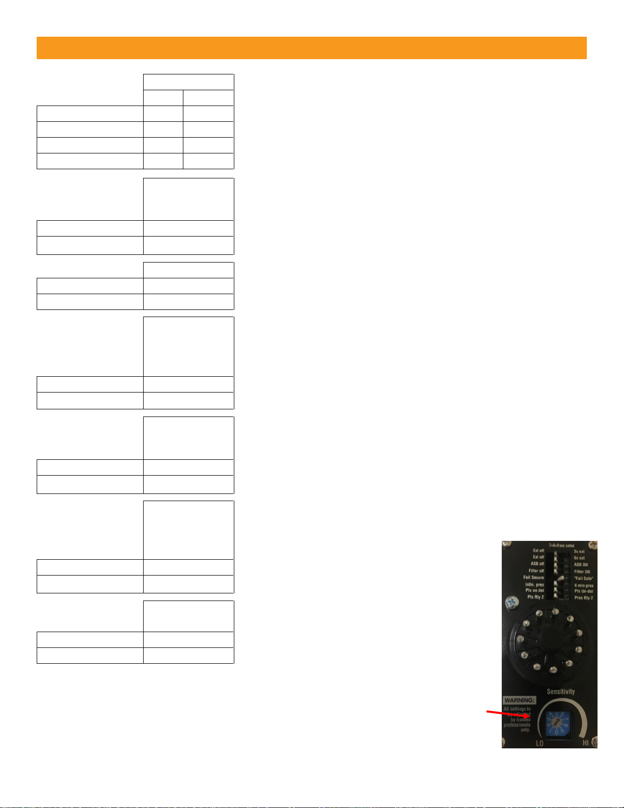
Sensitivity Setting
The 10-position rotary switch allows for adjustment of the detection level.
The sensitivity threshold increases from position 0 (lowest setting) through
9 (highest setting). Typical applications require a setting of 3 or 4. The rotary adjustment
must be set to a specific/whole number. There are no half settings.
EMX Industries, Inc. Tech support: 216-834-0761 4/7
MVP D-TEK_Rev2.0_081319 technical@emxinc.com
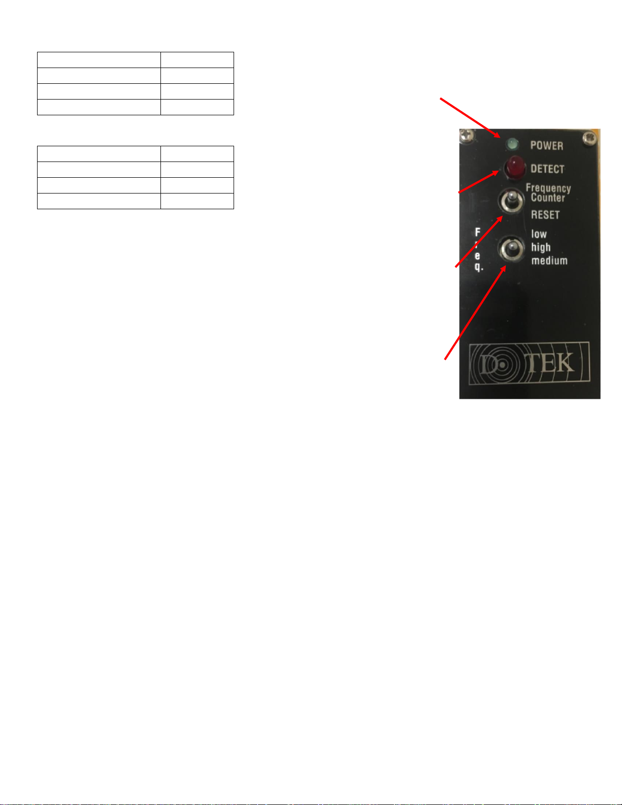
Power Green LED
The green LED is on when the device is
powered up and operating correctly.
No Power
off
Power
on
Previous Loop Fault
slow flash
Shorted or Open Loop
fast flash
Detect Red LED
The red LED is on when a vehicle
presence is detected and off when no
presence is detected. The red LED will
flash during extended detection and
when the frequency counter switch is
momentarily flipped up.
No Detection
off
Detection
on
Extended Detection
flash
Frequency Count
flash
Frequency Counter/ Reset Switch
Momentarily flipping the switch down calibrates the detector to the local
inductance field, DIP switch settings and frequency setting. Momentarily flipping
the switch up to check the operating frequency will cause the red LED to flash.
Each flash represents 10kHz. (For example, 5 flashes = 50KHz operating
frequency.) Counts from 3 to 13 confirm that the detector has tuned to the loop.
Frequency Switch
The frequency switch is used to assign the loop operation frequency.
The primary purpose of the frequency setting is to allow the installer the ability
to set different operating frequencies for multi-loop installations and is
recommended to prevent crosstalk/interference from multiple loops.
To check the operating frequency, refer to the frequency counter/reset switch.
Momentarily flip the RESET switch down after changing the frequency to calibrate
the detector to the local inductance field.
EMX Industries, Inc. Tech support: 216-834-0761 5/7
MVP D-TEK_Rev2.0_081319 technical@emxinc.com
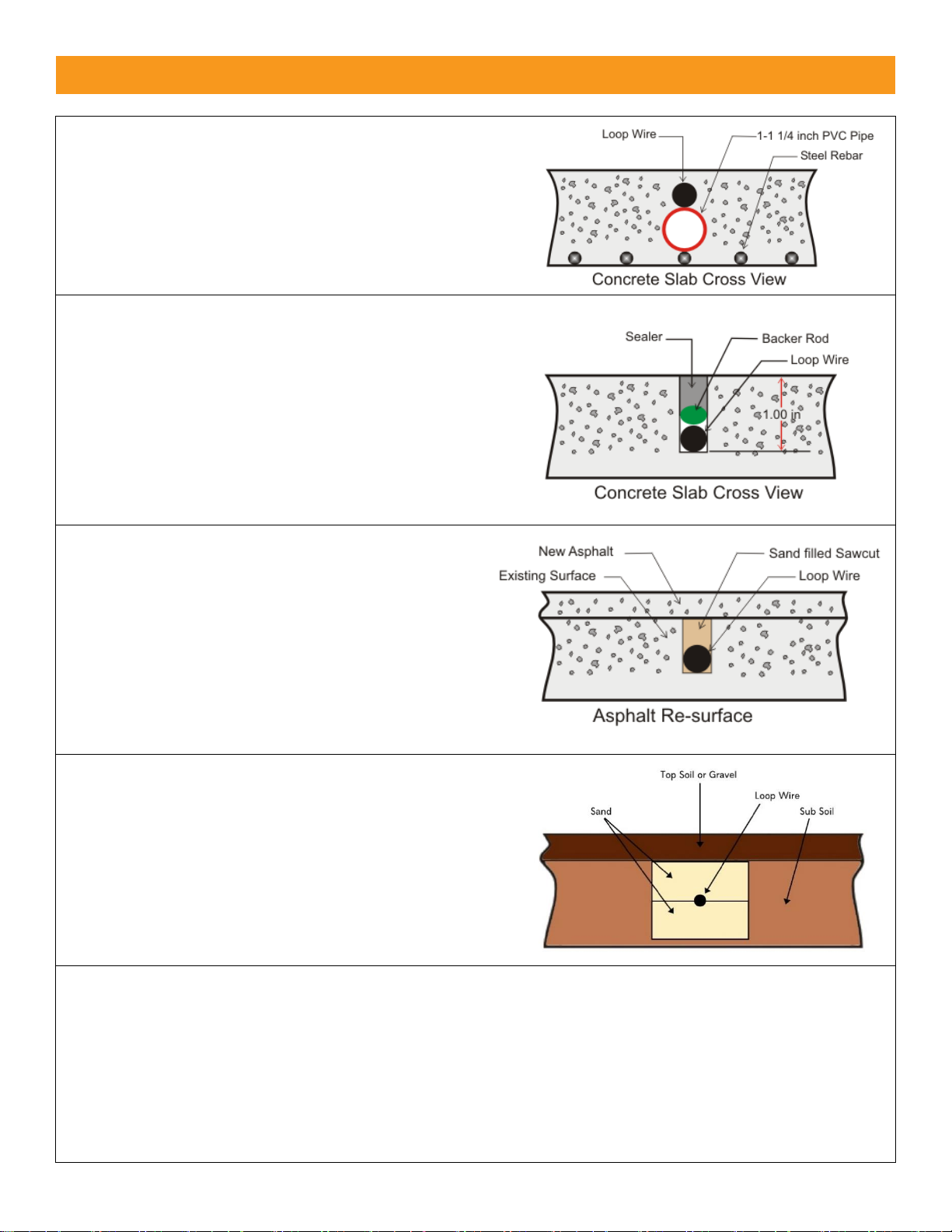
Loop Installation
NEW SLAB POUR
Ty-wrap 1-1/4” PVC pipe to the top of the rebar in the
size and configuration of the loop (ex. 4’ x 8’).
Then ty-wrap the loop to the top of the PVC frame.
This stabilizes the loop during the pour and separates
it from the rebar.
SAW CUT EXISTING SURFACE
Cut 1” deep into the existing surface, place a 45° cut at
the corners to prevent sharp edges from damaging the
loop wire. Notch out for the “T” connection where the
lead wire connects to the loop. Remove all debris from
the finished cut with compressed air. Place the loop
into the saw cut. Place backer material into the
saw cut over the loop wire and pack tightly. Place a
high-quality sealer over the saw cut to seal the surface.
RESURFACE ASPHALT
Saw cut the existing surface ¾” deep and place a 45°
cut at the corners to prevent sharp edges from
damaging the loop wire. Remove all debris from the
finished cut with compressed air. Place sand over
the loop wire to the surface and pack tightly.
Lay new asphalt.
GRAVEL OR SOIL INSTALLATION
While this is not a recommended installation for
most loops, it has been used successfully with
proper preparation. Remove gravel or top soil until
reaching a stable base. Dig ~ 6-8” deep by ~ 6-8” wide.
Fill halfway with sand and pack tightly. Place the loop
into the trench and finish filling to level with sand.
Pack tightly and replace gravel or soil over top.
GENERAL INSTALLATION GUIDELINES
• Use EMX lite preformed loops for quick, reliable installations.
• It is not recommended to install a loop near power lines (overhead or underground) or low voltage lighting.
If necessary near these power sources, place at a 45° angle. Make the loop shape a diamond, not a square.
• Never install a loop near inductive heaters.
• If using a non-preformed loop, lead-in wire (wire from loop to detector) must be twisted a minimum of
6 turns per foot to avoid the effects of noise or other interference.
• Detection height is approximately 70% of the shortest side of the loop.
For example: detection height for a 4’ x 8’ loop = 48” x .7 = 33.6”
EMX Industries, Inc. Tech support: 216-834-0761 6/7
MVP D-TEK_Rev2.0_081319 technical@emxinc.com
Installation
1. Configure DIP switch according to preferences. Refer to Settings & Display section for more
information.
2. Connect the 11 pin DIN rail socket or wire harness to the MVP D-TEK and connect an appropriate
power supply by pins 1 and 2 (white and black wire). Pin 4 (green wire) must be connected to earth
ground for effective surge protection.
3. Connect the loop wires to pins 7 and 8 (gray and brown wire).
4. Connect the operator wires to the DIN rail socket or wire harness, per one of the monitoring
methods below and according to the instructions provided by the operator manufacturer.
Relay 1 (Presence)
• Connect COM to pin 5 (yellow wire)
• Connect NO to pin 6 (blue wire)
• Connect NC to pin 10 (pink wire)
Relay 2 (Pulse/Presence)
• Connect COM to pin 9 (red wire)
• Connect NC to pin 11 (violet wire)
• Connect NO to pin 3 (orange wire)
• For Pulse, DIP switch 1 must be in off position
• For Presence, DIP switch 1 must be in on position
5. Adjust sensitivity setting to desired level to assure detection of all vehicle traffic. The sensitivity
level increases from position 0 (lowest setting) through 9 (highest setting). Typical applications
require a setting of 3 or 4. Any time the sensitivity setting changes, momentarily flip the
RESET switch down to calibrate the MVP D-TEK to the loop.
• To test the sensitivity, without moving the sensing loop, drive a vehicle near the loop.
Position the vehicle over the loop where the detection point is desired and change the
sensitivity settings to the lowest setting where detection occurs.
• The rotary adjustment must be set to a specific/whole number. There are no half settings.
6. If using multiple loops or suspect crosstalk/interference from the environment, perform
a frequency count on each detector to confirm that the operation frequencies are different.
• Momentarily flip up the frequency count switch and count the number of flashes of the
red LED. Each flash represents 10kHZ. Counts from 3 to 13 confirm that the detector is
tuned to a loop.
• If multiple loops and detectors are utilizing the same or very similar frequency,
change the frequency switch to a different low/high/medium setting on one of the
devices. For example: Move one MVP D-TEK to the low frequency setting and the second
MVP D-TEK to the high frequency setting.
7. Momentarily flip the RESET switch down to calibrate the MVP D-TEK to the loop.
TIP:

EMX Industries, Inc. Tech support: 216-834-0761 7/7
MVP D-TEK_Rev2.0_081319 technical@emxinc.com
Troubleshooting
Symptom
Possible Cause
Solution
Green LED not on
No power
Check the power supplied to the MVP D-TEK on
pins 1 (white wire) and 2 (black wire). Voltage should
read between 12-240 VDC/AC.
Green LED
fast flash
Loop wire shorted or not
connected
Check the loop resistance with a multimeter to confirm
a reading between 0.5 ohms and 5 ohms. If reading is
outside of this range, replace the loop. The reading
should be steady.
Check loop connections to terminals
Momentarily flip the RESET switch down
Green LED
slow flash
Loop wire was previously
shorted or open
Check the loop resistance with a multimeter to confirm
a reading between 0.5 ohms and 5 ohms. If reading is
outside of this range, replace the loop. The reading
should be steady.
Momentarily flip the RESET switch down
Red LED on
constantly (stuck
in detection
mode)
Faulty loop
Poorly crimped
connection or loose
connection
Perform a megger test from loop lead to ground,
it should be more than 100 megaohms.
Check loop connections to terminals. Verify splices are
properly soldered and sealed against moisture.
Detector detects
intermittently
when no vehicle
is on the loop
Faulty loop
Poorly crimped
connection or loose
connection
Cross-talk between
multiple loop detectors
Loop not securely
installed to prevent
movement of loop in
pavement.
Perform a megger test from loop lead to ground,
it should be more than 100 megaohms.
Check loop connections to terminals. Verify splices are
properly soldered and sealed against moisture.
Set multiple loops to different frequencies
Verify that loop is securely installed in pavement and
that site is in good condition preventing movement of
loop wires.
EMX Industries, Inc. products have a warranty against defects in materials and workmanship for a period
of two years from date of sale to our customer.
Warranty
 Loading...