


EMX Industries, Inc. Tech support: 216-834-0761 1/6
IRB-MON_Rev3.0_080619 technical@emxinc.com
IRB-MON
Universal Thru Beam Photoeye
Instruction Manual
The IRB-MON thru beam infrared photoeye is an external entrapment protection device type B1,
non-contact sensor for use with automatic gates and doors. The photoeye provides a signal to the gate
or door operator that the beam is or is not obstructed. The IRB-MON operates up to 115 feet over a
wide range of voltages (6-35 VDC and 12-24 VAC). A green alignment indicator on the receiver provides
status information at a glance, making set-up and alignment easy. The IRB-MON provides compatibility
with most operators that accommodate monitored external entrapment devices per UL325.
Cautions and Warnings
This product is an accessory or part of a system. Install the IRB-MON according to
instructions from the gate or door operator manufacturer. Comply with all applicable codes
and safety regulations.
Specifications
Operating Range
Up to 115 ft (35 m)
Power
6-35 VDC, 12-24 VAC
Current (NC and 10K Monitoring Methods)
60 mA (relay activated)
Current (Pulse Monitoring Methods)
15 mA
Surge Protection
Thermal fuse
Relay Output Operation
Light ON/Dark ON
Relay Output Configuration
Form C contacts (NO, COM, NC)
Transmitter Power Cycle
<300 mS (for use in NC or 10K monitoring)
Operating Temperature
-40° to 170°F (-40° to 77°C)
Dimensions (L x W x H)
2.3” (57 mm) x 2.6” (65 mm) x 3.7” (94 mm)
Environmental Rating
NEMA 4X
TM
EMX Industries, Inc. Tech support: 216-834-0761 2/6
IRB-MON_Rev3.0_080619 technical@emxinc.com
Ordering Information
• IRB-MON Thru beam photoeye, includes transmitter, receiver and sunshield
• IRB-HD-SET Gold anodized aluminum protective hoods
• IRB-SH-SET Gray powder-coated steel protective hoods
• IRB-SP Nylon liquid tight strain relief connector, set of two
• IRB-S Nylon mounting screws with nuts, set of two
• IRB-BR Steel “L” shaped mounting bracket, set of two
• IRB- RX-SH Receiver sunshield
Monitoring Methods
UL325 requires continuous monitoring of all safety devices connected to gate and door operators.
Consult the gate or door operator manufacturer’s instruction manual for necessary monitoring
method.
• Normally Closed: Cycles power to the transmitter while monitoring the receiver contacts for
proper operation
• 10K Resistive Termination: Provides a measurable 10K ohm resistance across the normally open
(NO) when unobstructed
• Two-wire Pulse (2 Frequency): Provides 300Hz “heartbeat” unobstructed, 0Hz obstructed over
power supply lines
• Two-wire Pulse (3 Frequency): Provides 300Hz “heartbeat” unobstructed, 2Hz obstructed, and
0Hz failure over power supply lines
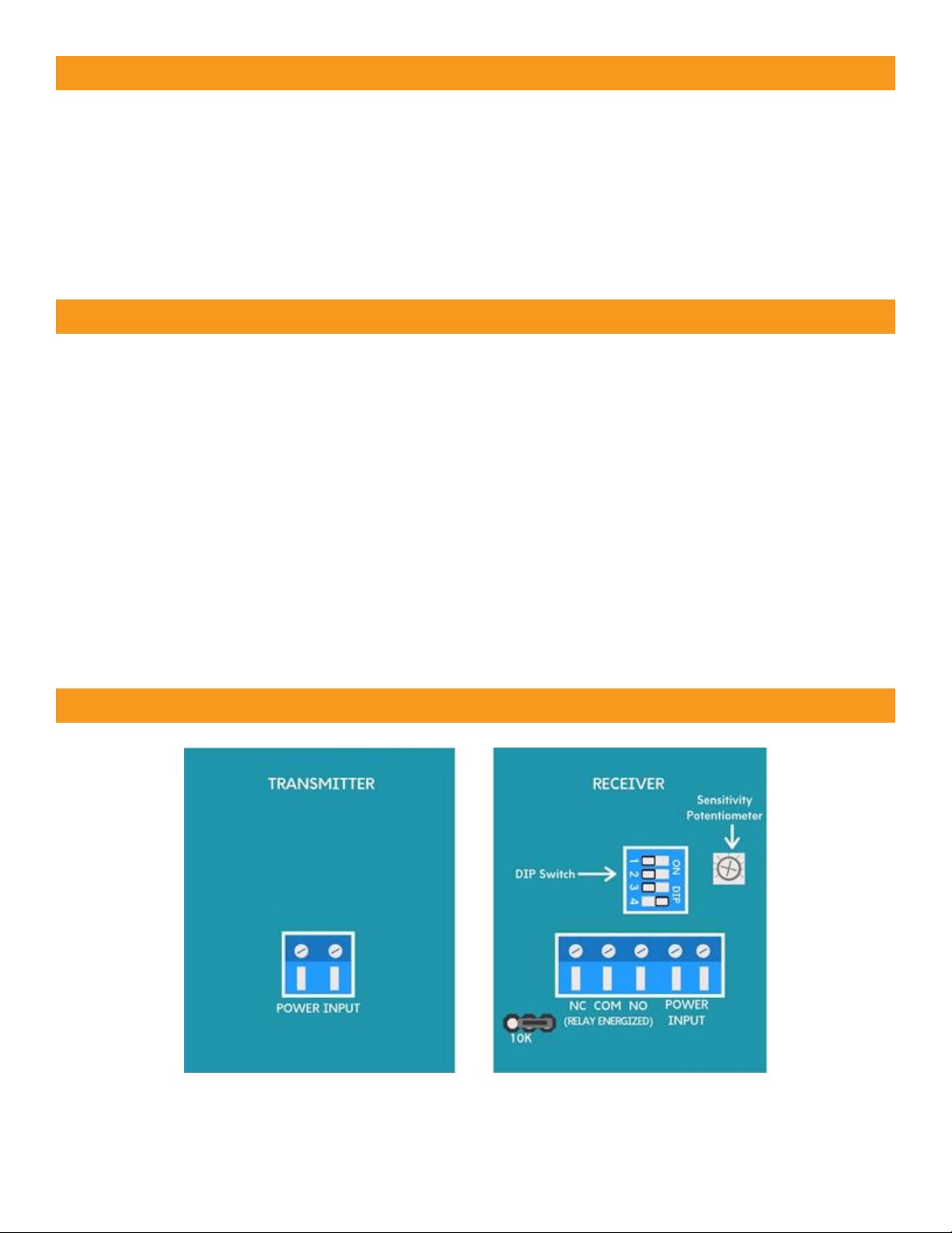
Board Diagram

EMX Industries, Inc. Tech support: 216-834-0761 3/6
IRB-MON_Rev3.0_080619 technical@emxinc.com
Installation
• Determine the mounting location of the IRB-MON photoeye according to UL325 guidelines.
• Deactivate the gate or door during photoeye installation.
• The IRB-MON cannot be used for a detection range of less than 5 feet.
1. Check the instruction manual of the gate or door operator
to determine which monitoring method is necessary for
that specific operator.
2. Knock out the PG hole on the housing that will be used to
wire through. Be careful not to damage electronic circuit
board when knocking out the hole.
3. Connect 6-35 VDC or 12-24 VAC power to the “Power Input”
terminals on the transmitter (marked “TX”) and receiver
(marked “RX”.) The power input terminals are not polarity
sensitive.
4. Install optional sunshield on receiver as shown to the right
to reduce the effects of solar interference or cross talk.
5. Wire the IRB-MON according to the configuration table and
wiring diagram that corresponds with the monitoring
method required by the gate or door operator.
MUST USE 6-35 VDC FOR PULSE MONITORING.
6. Make sure the covers are attached and closed tight using
all four plastic screws provided as shown. The wiring to the
enclosure must enter via UL listed watertight fitting such as
a strain relief or watertight conduit connector.
7. Verify that the IRB-MON transmitter and receiver are
aligned and apply power.
LED Indicators
Green transmitter LED on
Power
Green receiver LED on
Aligned
Green receiver LED flashing
Beam blocked or not aligned
8. The receiver and transmitter are aligned correctly when the green LED on the receiver is on. Decrease
the sensitivity setting on the receiver to the position where the green LED on the receiver starts to flash.
Then increase sensitivity setting one quarter turn. Confirm receiver LED is still on.
9. Place an obstruction (ex. hand) between the IRB-MON transmitter and receiver. The green LED on the
receiver will flash. Check the operator control board and verify that the safety input is recognized by
the operator. Test the beam with an obstruction between transmitter and receiver at multiple distances
to confirm proper operation.
10. Remove the obstruction and the green LED will turn on.
If the IRB-MON is aligned but not detecting an obstruction, consider slowly reducing sensitivity
(counter-clockwise) on the receiver until the obstruction is detected. This may be applicable for
installations with a detection zone of less than 20 ft.
TIP:
mounting screws
cover screws

EMX Industries, Inc. Tech support: 216-834-0761 4/6
IRB-MON_Rev3.0_080619 technical@emxinc.com
• Must use 6-35 VDC for pulse monitoring.
• The relay contacts labeled on the terminals and the references to them in these instructions are
shown in the energized state, no obstruction. (Dark ON setting – normally open (NO) contact closes
when the beam is unobstructed.)
• Pulsed configurations require current limiting in the operator. The IRB-MON will pulse 300Hz when
not obstructed and 0Hz when obstructed.
• DIP Switch 4 should be ON in virtually every configuration scenario.
When DIP Switch 4 is ON the relay will change state during a loss of power. This is sometimes referred
to as a “fail safe” mode. It is also sometimes referred to as Dark ON mode as the relay contact will be
in the closed position when under power and NOT obstructed.
• Dip Switch 4 is OFF in very rare installation scenarios. When Dip Switch 4 is OFF, the relay will function
in reverse. In addition, if DIP Switch 4 is OFF, during a loss of power the relay will
NOT change state during a loss of power. This is sometimes referred to as “fail secure” mode.
It is also sometimes referred to as Light ON (or Dark OFF) mode as the relay contact will be in the
open position when under power and NOT obstructed. WARNING: Leave DIP Switch 4 ON in all
normal operations and all UL 325 monitoring scenarios.
Configuration Settings and Wiring Diagrams
Monitoring
Method
Wiring
Diagram
DIP Switch Settings
Output
Connections
Jumper
SW1
SW2
SW3
SW4
Normally
Closed
A
OFF
OFF
OFF
ON
NC, COM
10K
disabled
10K
Resistive
Termination
B
OFF
OFF
OFF
ON
NO, COM
10K enabled
Two-Wire
Pulse (2
Frequency:
300Hz, 0Hz)
C
ON
OFF
OFF
ON
DC Power
10K
disabled
Two-Wire
Pulse (3
Frequency:
300Hz, 2Hz,
0Hz)
D
OFF
ON
OFF
ON
DC Power
10K
disabled

EMX Industries, Inc. Tech support: 216-834-0761 5/6
IRB-MON_Rev3.0_080619 technical@emxinc.com
Wiring Diagram A: Normally Closed
Wiring Diagram B: 10K Resistive Termination*
Wiring Diagram C: Two-Wire Pulse
(2 Frequency)
Wiring Diagram D: Two-Wire Pulse
(3 Frequency)
*If using the IRB-MON in an application
that does not require UL325 monitoring
across the normally open contact, it is
possible to disable the 10K resistor by
moving the 10K jumper to pins 2 and 3.

EMX Industries, Inc. Tech support: 216-834-0761 6/6
IRB-MON_Rev3.0_080619 technical@emxinc.com
Troubleshooting
Symptom
Possible Cause
Solution
Does not detect obstruction
Sensitivity is too high
Signal is reflecting off another
surface
Decrease sensitivity
potentiometer counterclockwise
Check area for highly reflective
surfaces
Receiver green LED flashes
continuously, indicating an
obstruction when one is not
present
Sensitivity is too low
Transmitter does not have
power
Receiver does not “see”
transmitter
Increase sensitivity
potentiometer clockwise
Check power source of
transmitter
Make sure transmitter and
receiver are aligned
Receiver activates but does not
transmit signal to operator
Faulty connection between
receiver and operator control
input
Verify all wires and terminal
connections
Receiver green LED off
Transmitter too close to receiver
Decrease sensitivity
potentiometer counterclockwise
Increase distance between
transmitter and receiver
Output relay chatters constantly
between open and close
All 4 DIP switches are in the OFF
position
Consult the Configuration
Settings table and set the
DIP settings according to the
UL325 monitoring method
detailed by the gate or door
operator manufacturer.
Warranty
EMX Industries, Inc. products have a warranty against defects in materials and workmanship for a period
of two years from date of sale to our customer.
 Loading...