

EMX WEL-200, WEL-200R, WEL-200T Operating Instructions Manual

4564 Johnston Parkway, Cleveland, Ohio 44128
P. 800 426 9912 F. 216 518 9884
Sales Inquiries: salessupport@emxinc.com
Technical Support: technical@emxinc.com
www.emxinc.com
WEL-200
W I R E L E S S E D G E L I N K
TM
O P E R A T I N G I N S T R U C T I O N S
Operating Instructions

Cautions and Warnings
Contents2
Specifications
3
Product Overview
4
Controls and Indicators
5
Connections
7
Installation and Operation
8
Troubleshooting
11
Ordering Information
15
WEL-200™ Operating Instructions 1
Document no. 10320104 Revision 2.0 3-1-18

FCC ID: 0A3MRF89XAM9A
This device complies with part 15 of the FCC Rules. Operation is
subject to the following two conditions: (1) This device may not
cause harmful interference, and (2) this device must accept any
interference received, including interference that may cause
undesired operation.
UL File: E315703
The WEL-200 is designed for use with Entrapment Protection Type
B2 devices per the 2018 UL325 standard. This system meets the
UL325 requirements for N.C., 10K resistive, 4-wire pulsed
monitoring methods.
Copyright Notice
Cautions and Warnings
1. Read and follow all operating and Installation instructions.
2. Always follow gate operator manufacturer installation instructions regarding installation
of type B2 devices to the operator.
3. Disable the gate so it is unable to move.
The WEL transmitter is designed for connection to a single
edge.
NEVER CONNECT MORE THAN ONE EDGE TO A SINGLE
TRANSMITTER!
When multiple edges are required, connect each edge to a
separate WEL transmitter for safe operation.
Regulatory Information
All rights reserved. Unless otherwise stated, the material within this document is copyright of EMX
Industries Inc. No part may be reproduced, in whole or in part, without the specific written
permission of EMX Industries Inc.
Refer servicing to qualified service personnel.
IMPORTANT:
This product is an accessory or part of a system. Always read and follow the manufacturer’s
instructions for the equipment before connecting this product. Comply with all applicable codes
and safety regulations. Failure to do so may result in damage, injury or death.
WEL-200™ Operating Instructions 2
Document no. 10320104 Revision 2.0 3-1-18
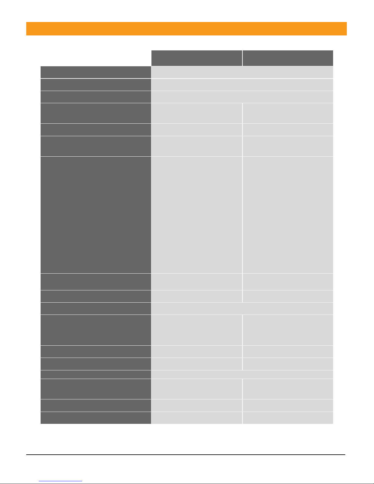
Specifications
WEL-200R
WEL-200T
Operating Range
Up to 200 ft. (line of sight)
Operating Frequency
915MHz
Response Time
100ms
Power/Fault Indicator
Red power LED/green
channel LED
Green transmit/status LED
Channel Status Indicator
Green LED
NA
Channel mode selection switch
Assign each channel to
OPEN/CLOSE function
NA
Outputs
OPEN direction relay:
Form C contacts (NO,
COM, NC)
CLOSE direction relay:
Form C contacts (NO,
COM, NC)
OPEN direction – 300Hz
pulsed: Open collector
transistor output
(opto-isolated)
CLOSE direction – 300Hz
pulsed: Open collector
transistor output
(opto-isolated)
NA
Resistive termination
10K ohm across NO contact
(jumper selectable)
NA
Power protection
Thermal fuse, MOV
Thermal fuse
Environmental Rating
NEMA 4X
Power Supply
12-24 VAC/VDC
3-3.6 VDC (2x AA batteries)
(ANSI 15-LF, IEC-FR14505
(FR6))
Battery life
NA
2 years at 25°C
Current Draw
50 mA
NA
Operating Temperature
-40°…60°C (-40°…140°F)
Dimensions (L x W x H)
140mm (5.5”) x 34mm (1.3”) x
90mm (3.5”)
180mm (7.0”) x 32mm (1.3”) x
67mm (2.6”)
Weight
200g (7 oz.)
170g (6 oz.)
Connections
12 terminals (18-26AWG)
2 terminals (18-26AWG)
WEL-200™ Operating Instructions 3
Document no. 10320104 Revision 2.0 3-1-18
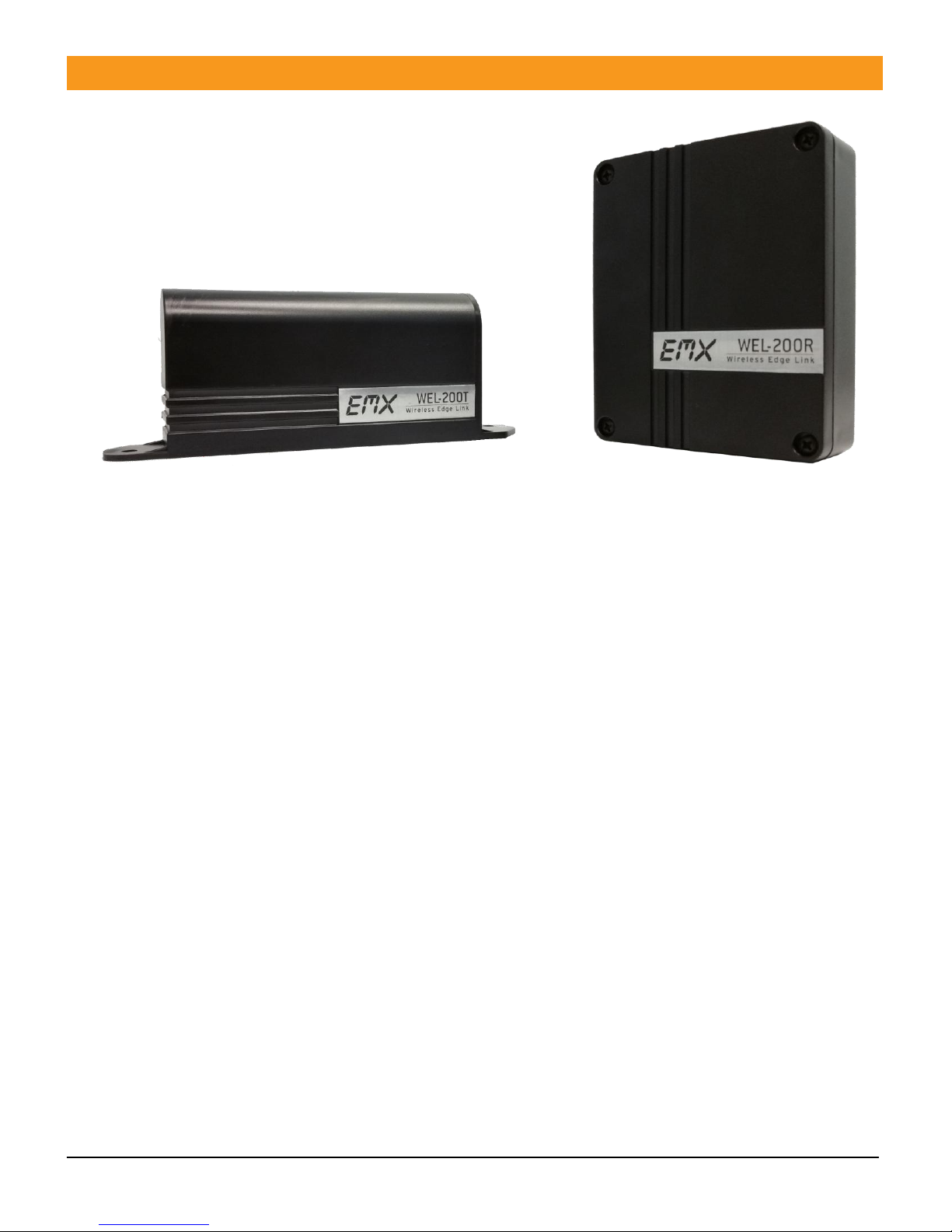
Product Overview
Figure 1 - WEL-200T (transmitter)
Figure 2 - WEL-200R (receiver)
The EMX WEL-200 system provides a complete wireless solution for interfacing sensing
edges with gate and door operators, while ensuring compliance with 2018 UL325
monitoring standards. Each transmitter can run for up to two years on two AA lithium
batteries. The receiver connects with up to four transmitters, with separate relay and
pulse outputs for open and close edge functionality.
With enhanced diagnostic features, the WEL-200R will make installation and
maintenance easy and reliable. Feedback is provided for all fault modes, including
edge open and short conditions, low battery, and failed transmitters.
WEL-200™ Operating Instructions 4
Document no. 10320104 Revision 2.0 3-1-18

Controls and Indicators
1. Channel assignment switches
- Assigns a wireless transmitter to the
specified channel
2. Channel status indicators
- Indicates current status of each channel
3. Wireless transceiver module
- Wireless radio used to communicate with
transmitters
4. Not used
5. Open/close direction assignment
switch
- Assigns channel to either open or close
direction output function
6. Power indicator
- On constantly when receiver is powered
up
7. Status indicator
- Shows current system status
8. “Close” direction relay termination
jumper
- Terminates the COM/NO terminals with a
10k resistor when jumper is placed in the
lower position
9. “Open” direction relay termination
jumper
- Terminates the COM/NO terminals with a
10k resistor when jumper is placed in the
lower position
10. Earth ground
- Connection point for earth ground
11. Terminal block
- Receiver I/O (see Table 1 in Connections)
Receiver
WEL-200™ Operating Instructions 5
Document no. 10320104 Revision 2.0 3-1-18
 Loading...