

EMX KPX-100 Instruction Manual
EMX Industries, Inc. Tech support: 216-834-0761 1/8
KPX-100_Rev2.0_090519 technical@emxinc.com
KPX-100
™
Programmable Keypad
Instruction Manual
The KPX-100 is a dual relay output, programmable keypad. It features a durable metal housing
and metal backlit keys designed for high traffic areas and harsh environments.
Connect this keypad to door strike controls, security systems or automatic gate and door operators.
The KPX-100 easily mounts on gooseneck stands, posts or walls.
Power
12-24 VDC/AC
Standby Current
16 mA
Detection Current
78 mA
Environmental Rating
IP66
Operating Temperature
-4º to 158ºF (-20º to 70ºC) 5 to 95% relative humidity
Housing Material
Powder coated steel with stainless steel faceplate
Dimensions (L x W x H)
6.14” (156 mm) x 4.1” (103 mm) x 2.76” (50 mm)
Specifications
Status
Tones
Left LED
Orange LED
Right LED
Programming Mode
---
---
Flashes
---
Successful Key Entry Relay 1
Determined by
code 81
---
1 flash
Solid green
LED
Successful Key Entry Relay 2
Determined by
code 81
Solid red LED
1 flash
---
Unsuccessful Key Entry
5 beeps
---
3 flashes
---
Successful Code Entry
2 beeps
---
2 flashes
---
Unsuccessful Code Entry
5 beeps
---
5 flashes
---
DAP Jumper Not Replaced
Continuous
beeps
---
Flashes continuously
---
Standby Mode
---
---
1 flash every
2 seconds
---
Lock-Up Mode
5 beeps
On
1 flash every
2 seconds
Solid red LED
Indicators
TM

EMX Industries, Inc. Tech support: 216-834-0761 2/8
KPX-100_Rev2.0_090519 technical@emxinc.com
Wiring Connections
1. Power (+): 12-24 VDC/AC
2. Power (-): 12-24 VDC/AC
3. Output 1: N.C. (normally closed contact)
4. Output 1: COM (common contact)
5. Output 1: N.O. (normally open contact)
6. Output 2: N.C. (normally closed contact)
7. Output 2: COM (common contact)
8. Output 2: N.O. (normally open contact)
9. Egress Input:
N.O. (normally open) input terminal.
More than one button can be connected in parallel.
Leave this terminal open if not in use.
10. Keypad Active Output:
This is an NPN transistor open collector output
with a maximum rating of 100mA sink and 24V DC.
It switches to ground for 10 seconds after
each key stroke. It is often used to turn on lights,
CCTV cameras or buzzers.
11. Duress Output:
This is an NPN transistor open collector output
with a maximum rating of 100mA sink and 24V DC.
It switches to ground after a duress key has been
entered. It is often used to trigger an alarm,
an auto dialer, or a buzzer.
12. Common Ground
13. Door Position Sensor Input:
N.C. (normally close) input terminal. See door sensor
wiring diagram to the right.
Always connect terminal 13 to ground if not in use.
14. Output 1 Inhibit:
N.O. (normally open) input terminal. Both relay 1 user keys and
egress button cannot activate output 1 while this terminal is tied to
ground. It is used in cross wire connections for inter-lock applications.
15. Inter-Lock Control Output:
This is an NPN transistor open collector output. It switches to ground for
the first 5 seconds after a valid user key is entered or after the egress
button is pressed. Use this output to control other keypads in inter-lock
applications.
16. & 17. Tamper N.C.:
N.C. (normally closed) contact while the keypad is secured in the housing.
It opens when the keypad is separated from the housing. To prevent
tampering connect this N.C. terminal to an alarm. See wiring diagram
to the right.
Back Lighting
Jumper
(see next page)
EMX Industries, Inc. Tech support: 216-834-0761 3/8
KPX-100_Rev2.0_090519 technical@emxinc.com
Wiring Diagrams
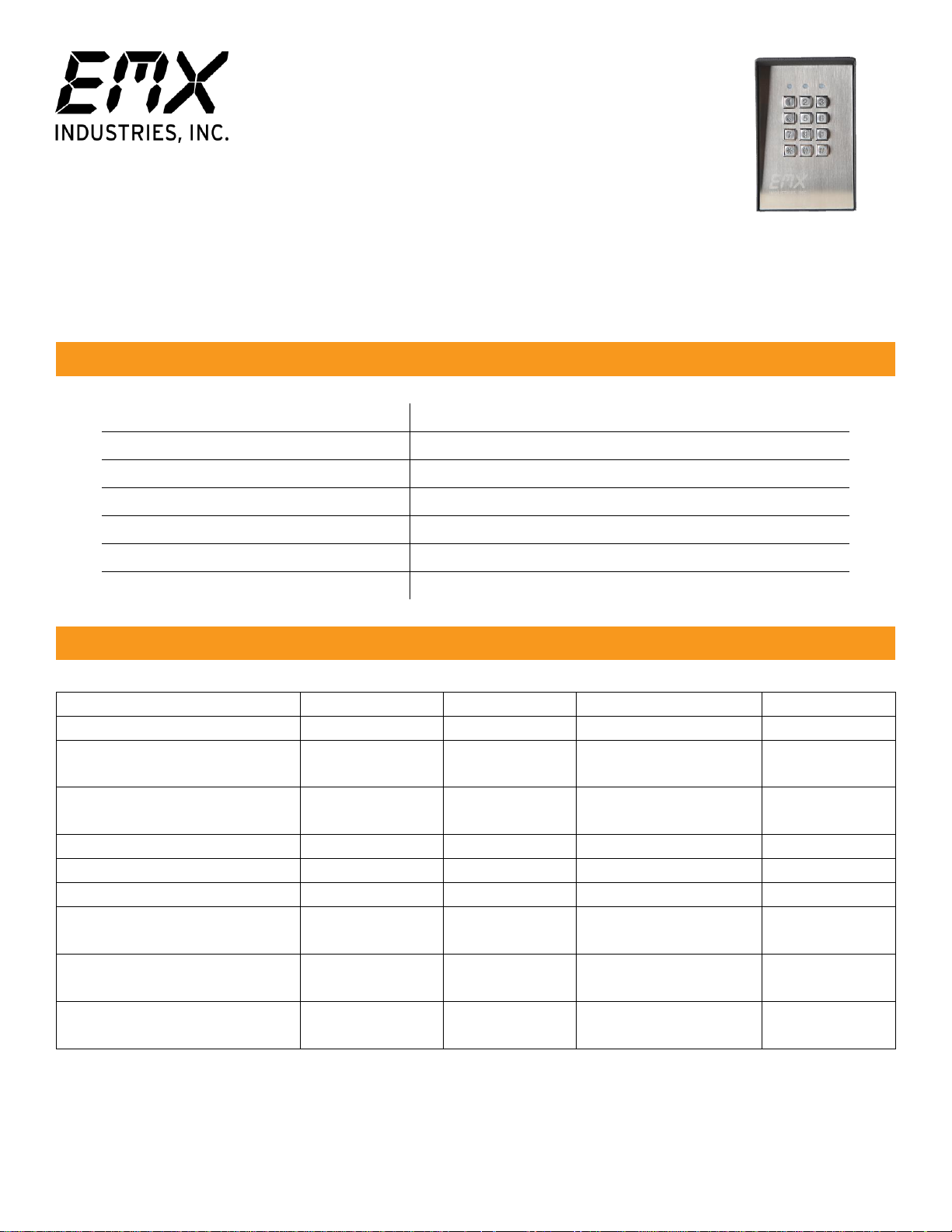
Single Door Wiring
• Connect the 1N4004 diode in
parallel with the lock terminals to
absorb the back EMF and prevent
damage to the keypad. This is not
required if the lock is AC powered.
• Connect common ground terminal
(12) to earth ground.
• Connect door position sensor
terminal (13) to ground if not in
use.
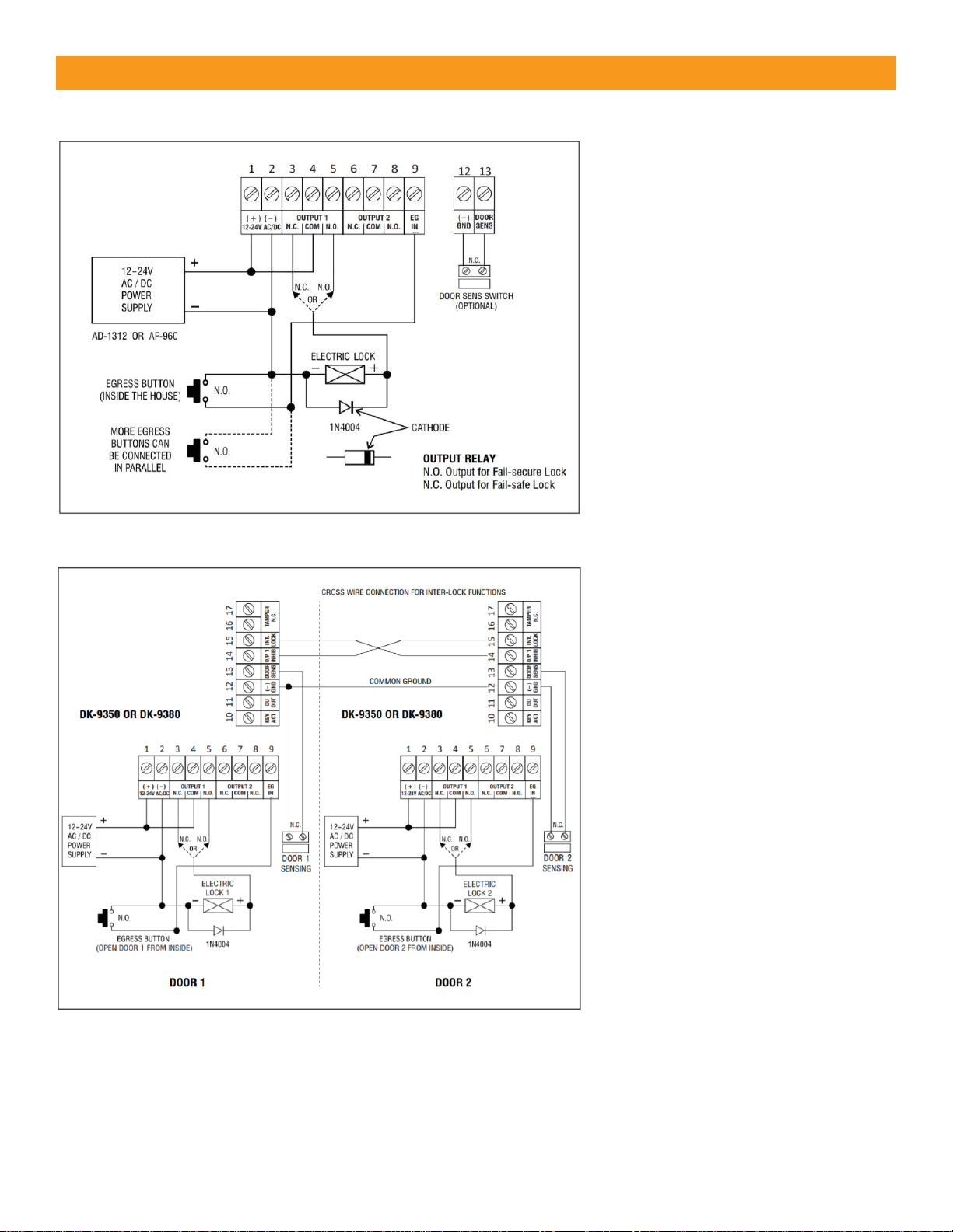
Inter-Lock Wiring
• This inter-lock system uses two
KPX-100 with cross wire
connections on the output 1
inhibit (14) and inter-lock control
output (15) terminals.
• Connect the common ground
terminals (12) of the two keypads.
• Use N.O. relay output for fail
secure locking and N.C. output for
fail safe locking.
• An inter-lock system prevents both
doors from being open at the
same time for a more secure
entry.
Keypad Back Lighting (jumper selected)
1. Backlit - The keypad is dimly lit standby. It turns to full back lighting with any keystroke.
2. Auto Backlit - The keypad is not lit standby. It turns to full back lighting with any keystroke.
It turns off 10 seconds after the last key stroke.
3. No Backlit - The keypad is never lit.
 Loading...