

Page 1
7
7
D
D
D
D
ayy
a
T
T
Prr
P
M--
M
o
grr
o
g
9
9
a
a
m
m
m
m
a
a
bll
b
e
e
Tii
T
m
m
err
e
Operating Instructions
This product is an accessory or part of a system. Always read and
follow the manufacturer’s instructions for the equipment you are connecting this
product to. Comply with all applicable codes and safety regulations. Failure to do
so may result in damage, injury or death!
Page 2
Installer notes:
Voltage installed:
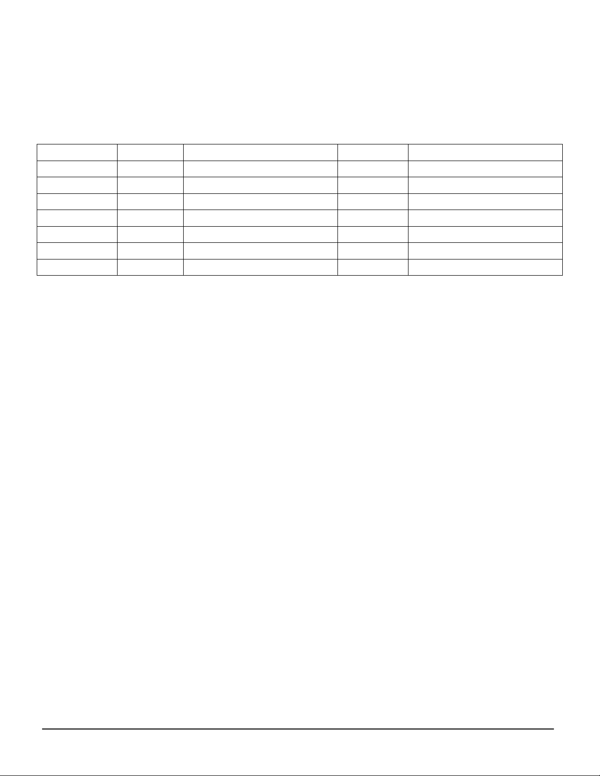
Settings Time on Days Time Off Days
Function 1 MO TU WE TH FR SA SU MO TU WE TH FR SA SU
Function 2 MO TU WE TH FR SA SU MO TU WE TH FR SA SU
Function 3 MO TU WE TH FR SA SU MO TU WE TH FR SA SU
Function 4 MO TU WE TH FR SA SU MO TU WE TH FR SA SU
Function 5 MO TU WE TH FR SA SU MO TU WE TH FR SA SU
Function 6 MO TU WE TH FR SA SU MO TU WE TH FR SA SU
DTM-9 Operating Instructions 2
Document no. REV 1.2 Date 07/03/2013
Page 3
Product Overview
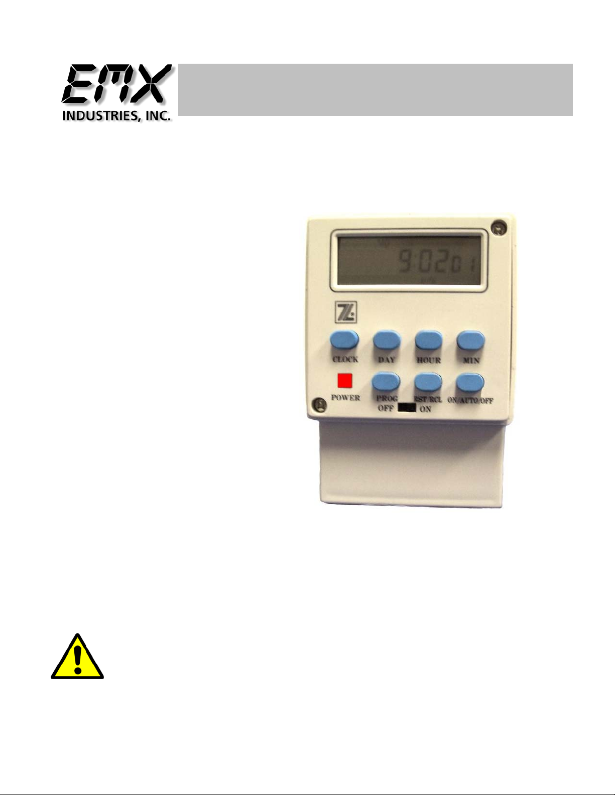
The DTM-9 7 Day Programmable Timer is able to be programmed with up to 6
ON/OFF events. By using it to hold open the gate or door during high usage times
you reduce the power required to operate the gate and reduce wear and tear on
the mechanical components.
Technical Specifications
Power Supply 12 Volt DC, 24 Volt AC/DC, 120 Volt AC
Power Supply Tolerance +/- 20% of power rating
Current Draw 60mA standby 74mA activated
Housing Material Break resistant Polycarbonate
H=4.00”(83mm), W=2.75”(40mm) D=2.25” (90mm)
Relay Type SPDT 5A@ 24VDC / 120VAC
Temperature Range -40 to 170 Degrees Fahrenheit
Connector Isolated Screw Terminal strip with 5 connections
Activation Indicator Red LED when relay is activated
Mounting DIN rail and flush mount bracket supplied
Surge Protection MOV protection devices
Memory Rechargeable back-up battery
Controls, Indicators and Connections
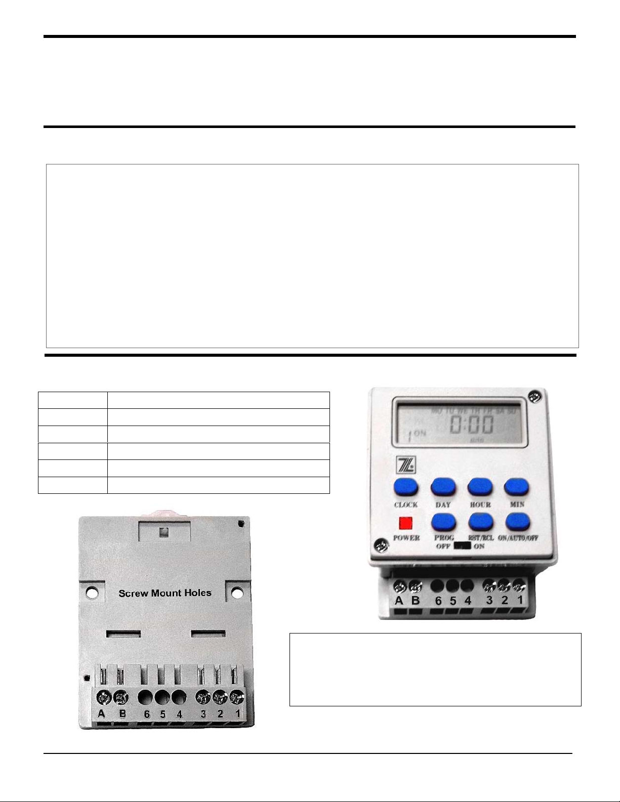
Terminal Function
A Power in positive
B Power in ground or negative
3 Relay output Normally Closed
2 Relay output Common
1 Relay output Normally Open
On activation terminals 1 and 2 will close
completing the circuit. The red LED will
illuminate indicating that the relay has
activated.
DTM-9 Operating Instructions 3
Document no. REV 1.2 Date 07/03/2013
Page 4
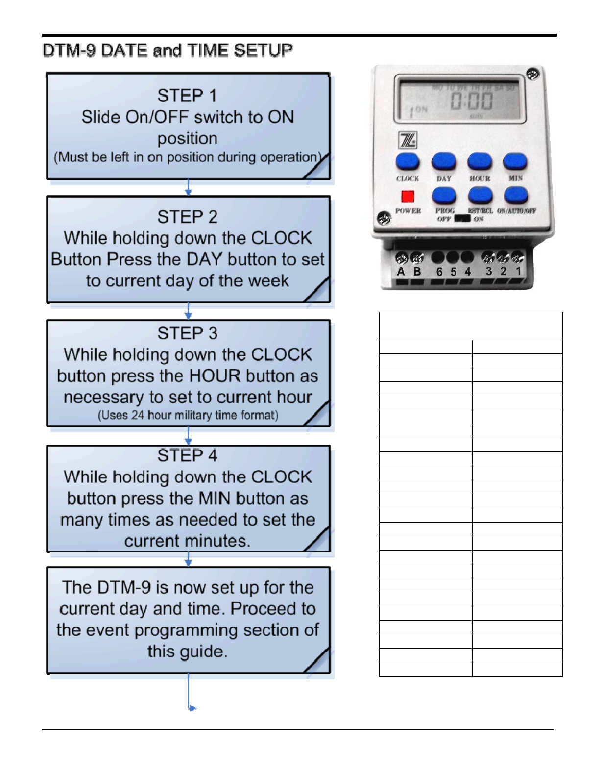
Military time conversion table
AM/PM MILITARY
1 am 01:00
2 am 02:00
3 am 03:00
4 am 04:00
5 am 05:00
6 am 06:00
7 am 07:00
8 am 08:00
9 am 09:00
10 am 10:00
11 am 11:00
12 noon 12:00
1 pm 13:00
2 pm 14:00
3 pm 15:00
4 pm 16:00
5 pm 17:00
6 pm 18:00
7 pm 19:00
8 pm 20:00
9 pm 21:00
10 pm 22:00
11 pm 23:00
12 midnight 24:00
DTM-9 Operating Instructions 4
Document no. REV 1.2 Date 07/03/2013
Page 5
DTM-9 Operating Instructions 5
Document no. REV 1.2 Date 07/03/2013
Page 6
Installation Instructions
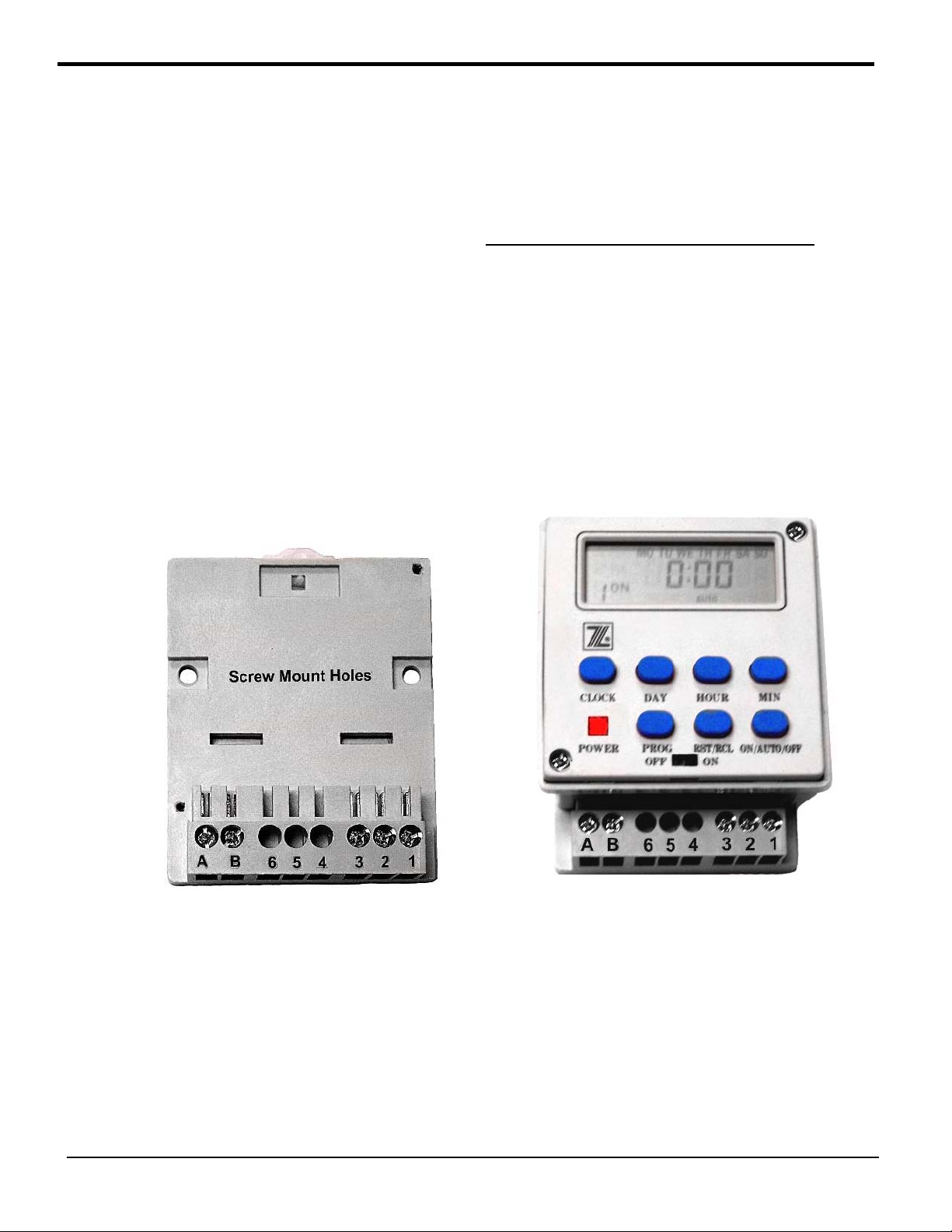
Install on DIN rail or use screws to mount base to surface. figure 1.1
(screw mounting holes)
Remove terminal block cover as shown in figure 1.2
Connect power to terminals “A” and “B”. Unit must be powered to operate
Connect terminal “2” (relay common) to correct terminal in operator control as
specified by operator manufacturer.
Connect terminal “1” (relay normally open) to correct terminal in operator control
as specified by operator manufacturer.
Note: Terminal “1” makes contact with terminal “2” when unit is activated.
Terminal “3” (relay normally closed) is contacted to terminal “2” when unit is not
activated.
Figure 1.1 Figure 1.2
Note: Battery life will be reduced if unit is powered off repeatedly each night.
Unit must be turned on and powered up to operate, the DTM-9 cannot run
off of the memory back-up battery.
Install timer away from inductive loads. Inductive loads must have MOV or
RC suppressors. If possible use a separate power source for the timer.
DTM-9 Operating Instructions 6
Document no. REV 1.2 Date 07/03/2013
Page 7

Ordering Information
DTM-9-12 12 Volt DC powered timer
DTM-9-24 24 Volt AC/DC powered timer
DTM-9-120 120 Volt AC powered timer
DTM-9 Operating Instructions 7
Document no. REV 1.2 Date 07/03/2013
Page 8

4564 Johnston Parkway
Cleveland, Ohio 44128
Technical Support Telephone (216) 834-0761
E-mail [email protected]
Sales Telephone (216) 518-9888
Fax (216) 518-9884
Email [email protected]
United States of America
WEB http://www.emxinc.com
DTM-9 Operating Instructions 8
Document no. REV 1.2 Date 07/03/2013
 Loading...