

Page 1
This product is an accessory or part of a system.
Always read and follow the manufacturer’s
instructions for the equipment you are connecting
this product to. Comply with all applicable codes and safety
regulations. Failure to do so may result in damage, injury or
death!
BBPPEE--550
0
™
Photo Beam with battery
powered Transmitter
Not UL325 compliant
Operating Instructions
Product Overview
The BPE-50 photo beam system uses 12 -24 VDC/AC on
the transmitter and receiver with the transmitter offering the
option of using the two 3.6 Volt batteries for power
(included). Recommended battery replacement is the Varta
ERAA 3V6 2400
.
Technical Specifications
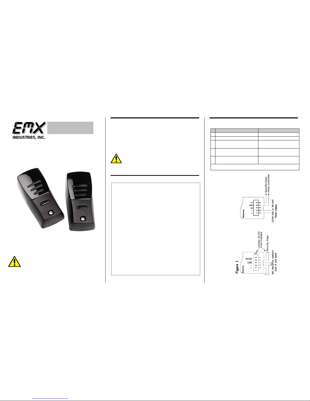
Connections (Fig 1)
Power Supply 12-24 VDC 24 VAC (2-3.6 Volt Lithium
Batteries for transmitter optional
/included)
Expected battery life up to 2 years
approx.
Current Draw RX = <50mA standby 100mA activated, TX
= < 500uA
Relay Type 2 Form C DPST contact rating .5A @ 24VDC
/ 120VAC
Temperature
-20C – 55C
Wavelength 880 nm
Frequency High 90 Hz Low 48 Hz (Ext power 787 Hz)
Environmental
IP 65
Detect Indicator Red LED
Connector Terminal block
Relay contact 0.5Amp
Housing Material PA6 30% FG
Size H 4.4in (112mm) x W 2.05in (52mm) x D
1.3in (33mm)
Range Up to 50 feet (if TX on 12/24 V 90 feet)
Detection Angle +/- 5%
Sensitivity Jumper J1 on receiver
Detection delay < 30 ms
Reset delay < 120 ms
Transmitter Receiver
1 Power Positive (+) Power Positive (+)
2 Power Negative (-) Power Negative (-)
3 NC Security Contact
(join if not used)
Internal Relay
Normally Open
4 Security edge
(join if not used)
Internal Relay
Common
5 Security edge
(join if not used)
Internal Relay
Normally Closed Output
Terminal connection as viewed from the front, left to right
WARNING … Not to be used for Personnel Protection
Never use product as sensing devices for personnel protection.
Doing so could cause serious injury or death.
These sensors do NOT include the self-checking redundant circuitry
necessary to allow their use in personnel safety applications. A sensor failure or
malfunction can cause either an energized or de-energized sensor output
condition. UL 325 Non-compliant
Page 2
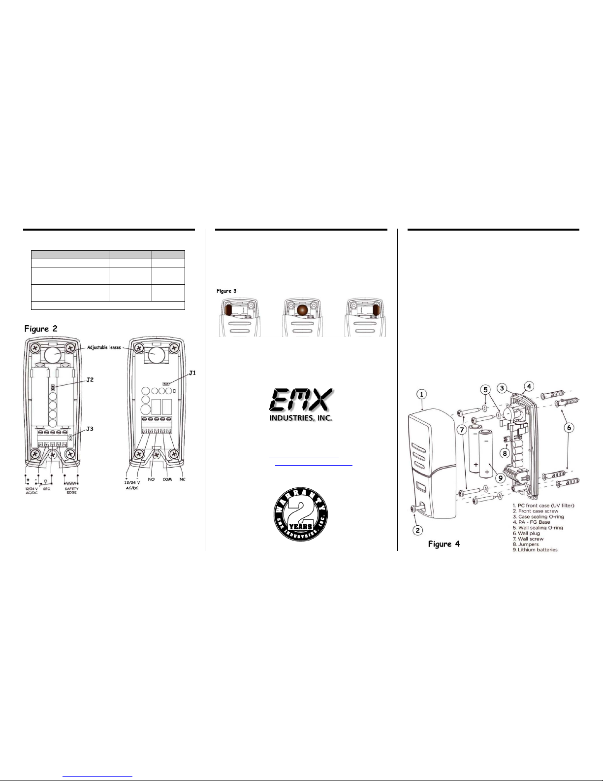
Both the transmitter and receiver lenses may be aligned
left, right or straight ahead. To align gently pull the lens
stem straight out from mounting position and snap back
into place pointing in the desired direction.
Units should be placed a minimum of 12 – 16 inches
from the floor. Across from and lenses facing each
other. The receiver red detect LED will be on when the
beam is broken or not aligned.
Place the BPE-50 away from heat and electromagnetic
sources for best operation. Mount units a minimum of
12 inches 30 cm from the floor.
Apply power to the units and set jumpers per instruction
on see figures 1 and 2.
Test installation to insure desired and proper operation.
All local and operator manufacturer installation
instructions should be followed.
The BPE-50 transmitter may be hooked up to an edge
sensor for alternative activation operation.
The BPE-50 does not require any special care, but it is
necessary to check condition occasionally to insure they
are operating correctly. (Batteries are still operational if
on battery power)
Recommended battery replacement is the Varta ERAA 3V6
2400
.
4564 Johnston Parkway
Cleveland, Ohio 44128
United States of America
WEB http://www.emxinc.com
E-mail [email protected]
Telephone (216) 518-9888
Fax (216) 518-9884
BPE-50 Instructions rev 1.1 06/19/2013
Jumper Configuration (Fig 2)
Lens Alignment (Fig 3)
Installation (Fig 4)
Jumper ON OFF
Receiver J1 (Gain) Normal High
Transmitter J2
(frequency)
Fast Slow
Transmitter J3 (Security
edge)
Not
connected
Connected
Jumper Settings for figure 2
When transmitter frequency is set to low battery
life will be increased. The range will be reduced
at this setting. However when the transmitter is
powered by 12/24 VDC or 24 VAC the range will
be maximum regardless of the jumper setting.
Page 3

SELF INSTALL - NEED TECHNICAL
ASSISTANCE?
OPTION 1: DIRECT WITH THE SERVICE DESK – QUICKEST AND MOST EFFECTIVE METHOD
Submit your enquiry direct with the service desk at – [email protected]
The service desk has the most experienced staff in Australia to help with your problem but they need your help.
Describe your problem in detail and as clearly as possible. Don’t forget to include a telephone number.
Be certain to detail which model or models of you are working with.
Send photos of the installation – they love photos. The people at the service desk are good but they are
even better when they can see the installation. Send photos of the overall scene so they can see the
entire installation. Also send photos of the wiring to the control board and any other part of the
installation you think is relevant.
Send video if appropriate. Smartphone’s these days take remarkably good video in small file sizes which
can be emailed in a moment. If your problem needs a video to show the issue please feel free to send it.
NOTE: THIS IS BY FAR THE FASTEST AND MOST SUCCESFUL WAY TO SOLVE YOUR PROBLEM
PHOTOS AND VIDEOS ARE THE NEXT BEST THING TO BEING THERE
OPTION 2: LODGE YOUR ENQUIRY LOCALLY - SLOWER BUT CAN STILL BE EFFECTIVE
Make contact with the store of purchase. Branch staffs are typically not technicians and dependent on their length
of service will have varying degrees of technical knowledge. If they cannot help however they will certainly either
source help locally from their technicians or make contact with the service technicians on your behalf.
OPTION 3: SERVICE CALL WITH AUTOMATIC SOLUTIONS TECHNICIAN – SLOWEST METHOD
If you fall within the local branch service area it may be possible to book a local technician to look at your
installation. Wait times will vary dependent on local workloads. The cost is a service fee which includes the first
half hour and the hourly rate thereafter. If any Automatic Solutions provided parts are found to be defective and
within warranty these will be provided free of charge.
(NOTE: If you suspect that any parts are defective and within warranty you may wish to consider option 4)
A note on this option: If you decide on this option you will be asked to sign an “authorisation to proceed” which
will provide legal authority and payment security. This form has three options available of which only the first two
are available to you. The third option is for warranty repairs only for full install customers. Self install customers
requiring warranty only service need to refer to option four below.
IMPORTANT: IN SHORT THIS OPTION WILL INCUR CHARGES
OPTION 4: RETURN THE PRODUCT IF BELIEVED TO BE FAULTY
As a self install customer who has purchased product if you believe the product to be faulty rather than an
installation or site problem you have the option of returning the product for evaluation and to exercise your right
to a replacement, repair or refund as applicable. All returned product is forwarded immediately to the service
technicians for evaluation and response. There are two main methods available to return product –
Direct to the service centre – this is the quickest method as it cuts out the branch delay
Via the branch of purchase – slower because of the delay at the branch
When choosing this option you need to complete a product return form. This form gives you all the information
on procedure involved and where to send to. These are available at the branch of purchase, can be emailed to
you (contact your branch), or available here - http://automaticsolutions.com.au/page/warranty.php
 Loading...