

Page 1
Technical Note
November 2014 | Version 1
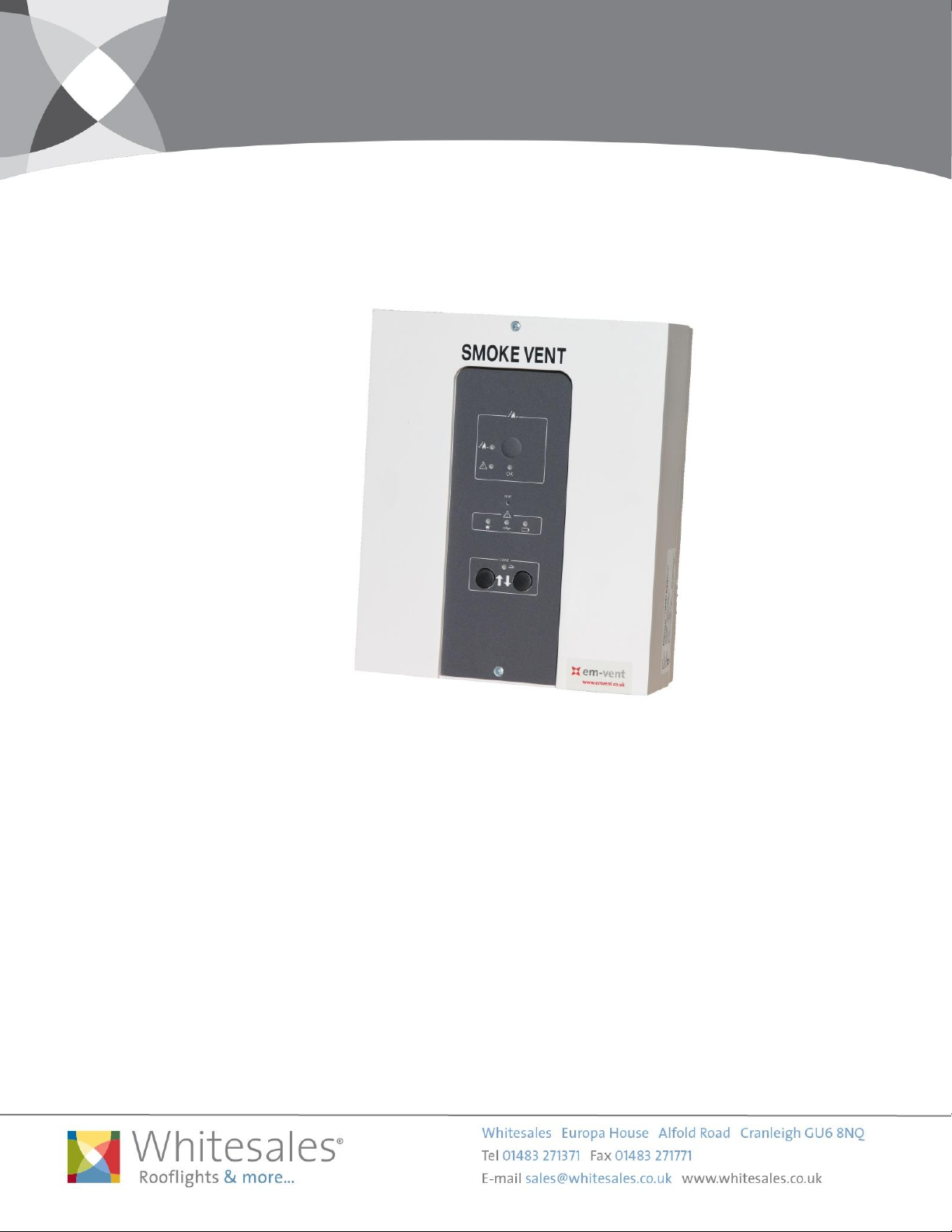
Em-Vent Smoke Control Panel Single Zone 5Amp (EVSCP24-5)
Product Description
5Amp / 1 fire group and 1 comfort group.
Em-Vent smoke vent control panels are constructed to provide and control the operation of the opening
systems for comfort and fire ventilation with 24V DC electrical actuators.
The Em-Vent smoke control panel is equipped with connection terminals for external signals (comfort and
fire switched, weather sensor/close all, detectors, etc), and it is also possible to connect more control
panel in the same ‘Bus’ connection.
The Em-Vent smoke control panel has a compact and elegant design and is certified according to EN
12101-10 class A (double supply) and EN 12101-9 (draft). Incl. battery back-up.
Page 2
Technical Note
November 2014 | Version 1
Specifications
EVSCP24-5
Approvals / Conforms
EN 12101-10: 2005 approved and certified – class A (double
supply) – envir. Class 1 (to -15˚C)
Conform to EN 12101-9
Power Supply
230V AC – max 1.5A
Output Supply
24V DC
Motor Outputs
1 pc. (line detection: 1-4 lines)
Max Total Load
5A
Operating Temperature
-15˚C - +40˚C
Density
IP 54
Battery Back-up (72hrs)
Yes
Batteries
2 pcs. 12V7, 2AH
Dimensions (WxDxH)
Weight incl. Batteries
238x113x286mm
7.5kg
Colour
White Front / Grey Indication Label
Fire Groups
1 pc. with line detection
Max power consumption for fire switches (LED+Buzzer) = 6.6mA =
approx. 3 manual control points
Comfort Groups
1 pc. - unlimited no. of comfort switches
Detector (Smoke/Heat) Input
1 pc. with line detection
Max power consumption for detectors = 2.2mA = approx. 22
detectors
Weather Sensor Input / Close All
Yes
Alarm Output
Yes – potential free contact, max 48V / 0.5A
Failure Output
Yes – potential free contact, max 48V / 0.5A
24V DC for External Use
24V DC / max 0.5A – at 230V AC operation
Bus Communication
Yes – connection of 2-10 control panels – line detection
Visual (LED) Indication in Front Panel
‘OK’ / ‘AC Fault’ / ‘Low Battery’ / ‘Line Fault’ / ‘Alarm’ / ‘Comfort
Open’
DIP Switch Features (Standard)
Service hours (LED’s flash in front panel)
Comfort opening interval
Temperature detection via motor output
Extra line detection via 3 wire motor output
Fail safe (alarm by line failure)
Sprinkler (close by alarm)
Bus comm. settings (react on Bus comm.)
Potential free contact for comfort open
Specific Characteristics
Page 3
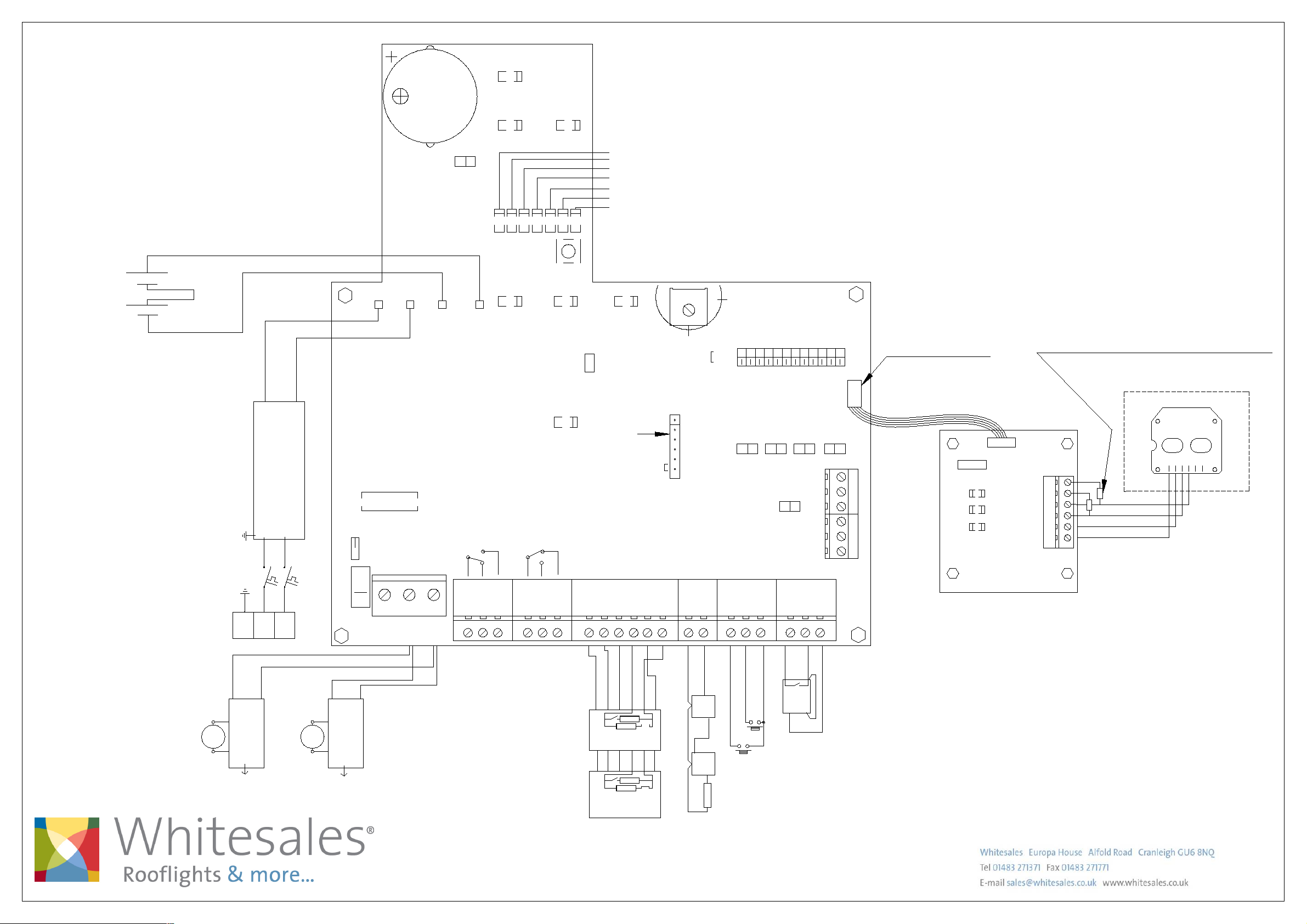
Wiring Diagram
Em-Vent Smoke Control Panel
RED
ALARM
BUZZER
EVSCP24-5
EVSCP24-8
+
+
-
Batteries 2x 12V - 7,2 /12 Ah
Red 2,5mm224V
Black 2,5mm2
- 24VDC +
PS1
24VDC 150W/200W
Power Supply 180-250 VAC
L1PE
N1
10 A Autofuse
PS -
Max. 8A
FUSE F1 - fas t
Actuato r
Motor line mo nitor
Ext 3 wi re mon itor (line 1)
J2
4 J3
3
2
1
Line 1
PS +
21
Actuato r
24V Out
J1
BUZZER ON/O FF
BAT -
Alarm Out Failure Out
3
4
YEL
FAILURE
RED
GRE
BAT +
AC FA IL LINE FAIL
NO
COM5NC
6
RED
COM
7
GRE
OK
RED
RED
RED
RED
RESE T
YELYEL
NTC
BLUE
DOME O PEN
Without k eyboard jumper m ounted
NO
8 9
NC
OK 24V
10
11 12
LD1 Actuator open (red). Lit when actuator is opening.
LD2 Actuator closing (green). Lit when actuator is closing.
LD3 Weather sensor active (red). Lit when weather sensor is active.
LD4 Line failure actuator (red). Lit for line failure on actuator.
LD5 Line failure fire switch (red). Lit for line failure on fire switch.
LD6 Line failure smokesensor (red). Lit for line fail. on smokes.
LD7 BUS failure (red). Lit when local unit is not recieving signal.
Potmeter for
comfort features
Max.
P
YEL
u
l
BATT LOW
s
v
a
r
ia
b
l
e
DIP settings see page 13
Keyboard
24V
Gnd
Fail. 24V
ALARM
FIRE
Reset
14
15
13
Min
J9
Set J11 for batte ri backup
of terminal 23
Gnd16Smoke
s
n
o
C
ON
OFF
STAR T TER M.
17
Puls
.
t
FAIL S AFE
SERV ICE TIM ER
TEMP DETECT
Con. F ire. Sw
→
→
21DIP NO
STAR T termi nation
J4
Down
Up
Gnd
19
20 21
18
AG M ODE
SNITC H
BUS M aster
J11
SPRI NKLER
BUS COMFOR T
WEEK OPEN
FAIL R ELAY M .
BUS S lave
Gnd
Weather
22 23
BUS FIRE
109 1185 7643 12
J15
J7J6J5
END TE RM.MAST ER SLAV E
Serial Out
Serial In
24V
DSW
BL
END terminati on
→
B3
→
B2
→
B1
→
A3
→
A2
→
A1
Connection to SVM Add-Onn
Connection to
next unit.
up to 35 pcs. control units.
prev. unit.
Busconnection for serial connection
Connection from
Remove resistors when
mounting Firemans Priority Switch
Firemans Priority Switch (EVSFPS)
Firemans Priority Switch
OPEN
CLOSE
61
6
5
2 3 4
1
Blue
M1
Brown
2
5
6
3
Next LIP
1 1
2
Blue
LIP #1
4
M1
Brown
5
LIP #1
6
3
4
Next LIP
1 channel LIP
(LIP5/ LIP6)
example
CH 1
Potential free ALARM switch.
Com + NO connected on alarm.
Max 48V 0,5A
Extra relay print 111655
provides 4 additional
potential free switches
each 30V 0,5A
Smoke o r
heat sens ors
Red LE D
Green L ED
Yello w LED
4 762 31
680Ω
Ω
10 K
Manual control point,
Break glass (EVSMCP)
no 1
32
Com + NC connected on failure.
Max 48V 0,5A
Potential free Failure switch.
1
2
1
10 KΩ
Manual control point,
Break glass (EVSMCP)
fit jumper in last
4
43
680Ω
J1
6
7
6
7
J1
L2
Nr.1
L1 In
L2
Nr.2 -20
L1 In
L1 O ut
L1 O ut
10 KΩ
Dow n
Up
Comfort
3 5
1 2
Switch Ch 1
(Close all)
Wind and rain sensor
Place resistor in last detector
Connection diagram SVM Whitesales
Drawing: 211707 B
 Loading...