

Page 1

EMUS BMS mini
User Manual v0.8
1
Page 2

Contents
1 System structure overview 5
2 Setting up the BMS 6
2.1 Battery cells installation . . . . . . . . . . . . . . . . . . . . . . . . . . . . . . . . 6
2.2 Connecting temperature sensors . . . . . . . . . . . . . . . . . . . . . . . . . . . . 8
2.3 Charger installation . . . . . . . . . . . . . . . . . . . . . . . . . . . . . . . . . . 9
2.3.1 Non-CAN based charger . . . . . . . . . . . . . . . . . . . . . . . . . . . . 9
2.3.2 CAN based charger . . . . . . . . . . . . . . . . . . . . . . . . . . . . . . 12
2.4 Load installation . . . . . . . . . . . . . . . . . . . . . . . . . . . . . . . . . . . . 13
3 Core BMS functionality 14
3.1 Battery Monitoring . . . . . . . . . . . . . . . . . . . . . . . . . . . . . . . . . . . 14
3.1.1 Voltage Monitoring . . . . . . . . . . . . . . . . . . . . . . . . . . . . . . 14
3.1.2 Current Measurement . . . . . . . . . . . . . . . . . . . . . . . . . . . . . 14
3.1.3 Temperature measurement . . . . . . . . . . . . . . . . . . . . . . . . . . . 15
3.2 State of Battery . . . . . . . . . . . . . . . . . . . . . . . . . . . . . . . . . . . . 15
3.2.1 Charge estimation . . . . . . . . . . . . . . . . . . . . . . . . . . . . . . . 15
3.2.2 Health estimation . . . . . . . . . . . . . . . . . . . . . . . . . . . . . . . 15
3.3 Charging process . . . . . . . . . . . . . . . . . . . . . . . . . . . . . . . . . . . . 15
3.3.1 Using Non-CAN charging device . . . . . . . . . . . . . . . . . . . . . . . . 16
3.3.2 Using CAN charging device . . . . . . . . . . . . . . . . . . . . . . . . . . 16
3.3.3 Configuration . . . . . . . . . . . . . . . . . . . . . . . . . . . . . . . . . 17
3.4 Battery Protections . . . . . . . . . . . . . . . . . . . . . . . . . . . . . . . . . . 17
3.4.1 Cell Over-Voltage Protection . . . . . . . . . . . . . . . . . . . . . . . . . 17
3.4.2 Cell Under-Voltage Protection . . . . . . . . . . . . . . . . . . . . . . . . . 17
3.4.3 Charge Over-Current Protection . . . . . . . . . . . . . . . . . . . . . . . . 18
3.4.4 Discharge Over-Current Protection . . . . . . . . . . . . . . . . . . . . . . 18
3.4.5 External Over-Temperature Protection . . . . . . . . . . . . . . . . . . . . 18
3.4.6 External Under-Temperature Protection . . . . . . . . . . . . . . . . . . . . 18
3.4.7 Internal Over-Temperature Protection . . . . . . . . . . . . . . . . . . . . . 18
3.4.8 Configuration . . . . . . . . . . . . . . . . . . . . . . . . . . . . . . . . . 18
3.5 Contactor pre-charge . . . . . . . . . . . . . . . . . . . . . . . . . . . . . . . . . . 19
4 Data interfaces 20
4.1 Wireless smartphone connectivity . . . . . . . . . . . . . . . . . . . . . . . . . . . 20
4.2 CAN . . . . . . . . . . . . . . . . . . . . . . . . . . . . . . . . . . . . . . . . . . 20
4.2.1 Installation . . . . . . . . . . . . . . . . . . . . . . . . . . . . . . . . . . . 22
4.2.2 Configuration . . . . . . . . . . . . . . . . . . . . . . . . . . . . . . . . . 22
5 Remappable GPIO Functions 23
5.1 Description . . . . . . . . . . . . . . . . . . . . . . . . . . . . . . . . . . . . . . . 23
5.2 Configuration . . . . . . . . . . . . . . . . . . . . . . . . . . . . . . . . . . . . . . 24
6 Analytics 25
6.1 Statistics . . . . . . . . . . . . . . . . . . . . . . . . . . . . . . . . . . . . . . . . 25
6.2 Events . . . . . . . . . . . . . . . . . . . . . . . . . . . . . . . . . . . . . . . . . 27
7 Status Parameters 28
8 Maintenance 30
1
Page 3

8.1 Firmware Update . . . . . . . . . . . . . . . . . . . . . . . . . . . . . . . . . . . . 30
8.2 Password protection . . . . . . . . . . . . . . . . . . . . . . . . . . . . . . . . . . 30
8.2.1 User types . . . . . . . . . . . . . . . . . . . . . . . . . . . . . . . . . . . 30
8.2.2 Enabling password protection . . . . . . . . . . . . . . . . . . . . . . . . . 31
8.2.3 Logging in . . . . . . . . . . . . . . . . . . . . . . . . . . . . . . . . . . . 31
8.3 Time and Date . . . . . . . . . . . . . . . . . . . . . . . . . . . . . . . . . . . . . 31
9 Software 33
9.1 Mobile application . . . . . . . . . . . . . . . . . . . . . . . . . . . . . . . . . . . 33
10 Technical information 34
10.1 BMS mini . . . . . . . . . . . . . . . . . . . . . . . . . . . . . . . . . . . . . . . 34
10.1.1 Mechanical specifications . . . . . . . . . . . . . . . . . . . . . . . . . . . 34
10.1.2 Electrical specifications . . . . . . . . . . . . . . . . . . . . . . . . . . . . 35
10.1.3 Other specifications . . . . . . . . . . . . . . . . . . . . . . . . . . . . . . 35
2
Page 4

List of Abbreviations
BMS Battery Management System
PWM Pulse Width Modulation
RPM Revolutions per minute
LIN Local Interconnect Network
CAN Controller Area Network
GPIO General Purpose Input Output
PC Personal Computer
AC Alternating Current
NC Normally Closed
List of Tables
Table 3.1: External current sensor operating current range . . . . . . . . . . . . . . . . 14
Table 3.2: External current sensor current update rate . . . . . . . . . . . . . . . . . . 14
Table 4.1: Maximum bus line lengths, calculated based on the used CAN bit timing
setting, considering that a twisted-pair cable with a typical propagation delay
of 5 ns/m is used. LU- maximum length of a single unterminated drop line,
P
LU- maximum length of all unterminated drop lines together. . . . . . . . 21
Table 5.1: List of standard set input functions . . . . . . . . . . . . . . . . . . . . . . 23
Table 5.2: List of special set input functions . . . . . . . . . . . . . . . . . . . . . . . 23
Table 5.3: List of standard set output functions . . . . . . . . . . . . . . . . . . . . . 23
Table 5.4: List of special set output functions . . . . . . . . . . . . . . . . . . . . . . 24
Table 6.1: List of statistics and their descriptions . . . . . . . . . . . . . . . . . . . . 25
Table 6.2: List of events and their descriptions . . . . . . . . . . . . . . . . . . . . . . 27
Table 10.1: Fastening screws . . . . . . . . . . . . . . . . . . . . . . . . . . . . . . . . 34
Table 10.2: BMS mini Electric Specifications . . . . . . . . . . . . . . . . . . . . . . . 35
Table 10.3: BMS mini Physical Specifications . . . . . . . . . . . . . . . . . . . . . . . 35
List of Figures
Figure 1.1: System structure . . . . . . . . . . . . . . . . . . . . . . . . . . . . . . . 5
Figure 2.1: Battery connection diagram . . . . . . . . . . . . . . . . . . . . . . . . . 6
Figure 2.2: Example system 24 V (7 battery cells) . . . . . . . . . . . . . . . . . . . . 7
Figure 2.3: Example system 36 V (10 battery cells) . . . . . . . . . . . . . . . . . . . 8
Figure 2.4: External Temperature Sensor . . . . . . . . . . . . . . . . . . . . . . . . . 8
Figure 2.5: External Temperature Sensor installation diagram . . . . . . . . . . . . . . 9
Figure 2.6: Uncontrolled Non-CAN charger installation diagram . . . . . . . . . . . . . 10
Figure 2.7: Controlled Non-CAN charger installation diagram . . . . . . . . . . . . . . 11
Figure 2.8: 10-pin Pin Function connector . . . . . . . . . . . . . . . . . . . . . . . . 11
Figure 2.9: CAN charger wiring diagram . . . . . . . . . . . . . . . . . . . . . . . . . 12
Figure 2.10: CAN connector . . . . . . . . . . . . . . . . . . . . . . . . . . . . . . . . 13
Figure 2.11: Load installation diagram . . . . . . . . . . . . . . . . . . . . . . . . . . . 13
Figure 4.1: High-speed CAN network specified in ISO-11898-2 standard . . . . . . . . . 20
Figure 5.1: Pin function connector pinout . . . . . . . . . . . . . . . . . . . . . . . . 23
3
Page 5

Figure 5.2: Input and output pin configuration: a) High voltage sensing input, b) Ground
sensing input, c) High voltage output . . . . . . . . . . . . . . . . . . . . 24
Figure 9.1: EMUS BMS mini mobile application . . . . . . . . . . . . . . . . . . . . . 33
Figure 10.1: BMS mini mechanical drawing . . . . . . . . . . . . . . . . . . . . . . . . 34
4
Page 6
1 System structure overview
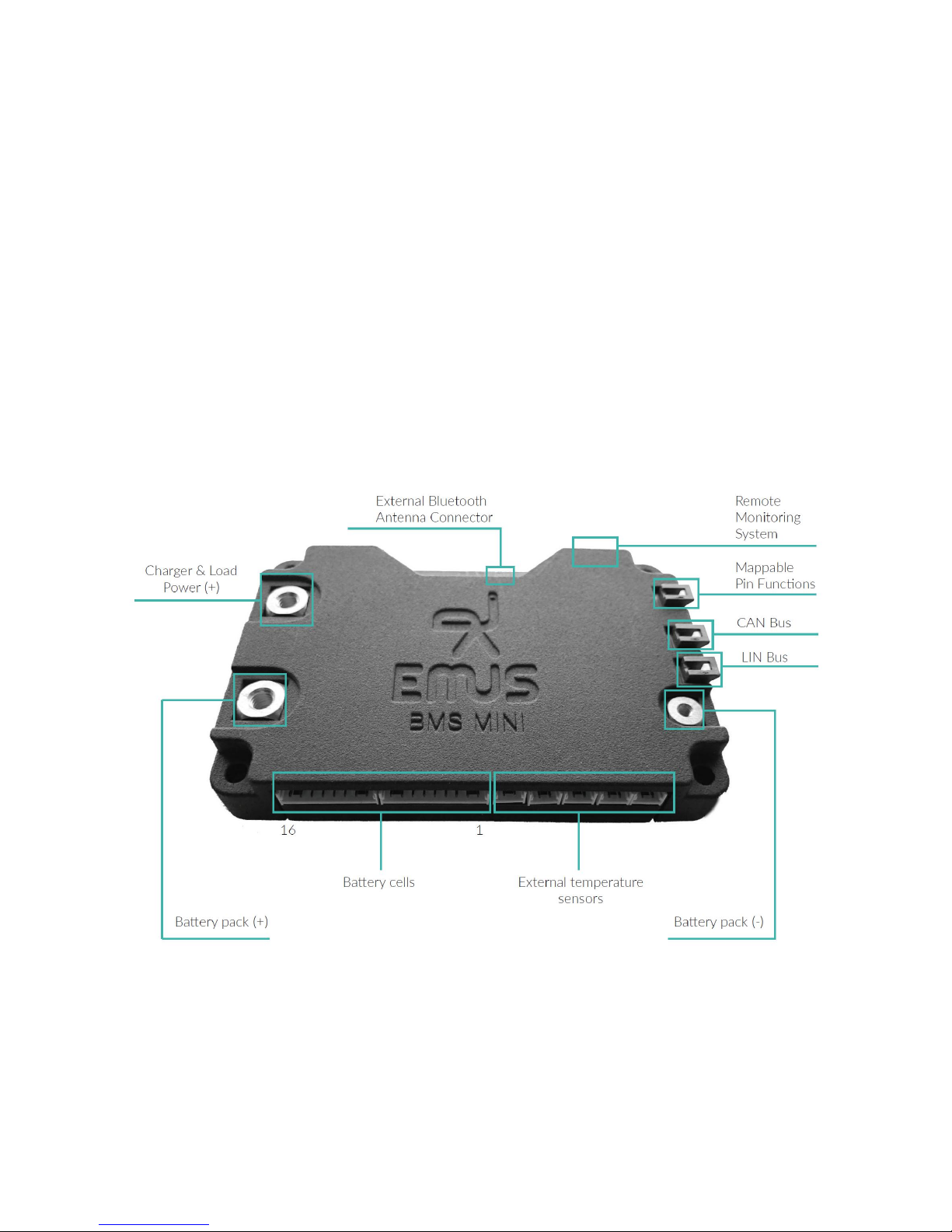
EMUS BMS mini is a centralized battery management system that consists of a main controller
and optional components that serve different purposes or amplifies the integrated ones. All of the
populated pins and tabs of the main controller are described below:
• pins dedicated to connecting battery cells
• 5 connectors for external temperature sensors
• 9 multi-purpose input/output programmable pins
• CAN Bus
• LIN Bus
• Battery power tabs
• Load/Charger power tab
Figure 1.1: System structure
5
Page 7
2 Setting up the BMS
2.1 Battery cells installation
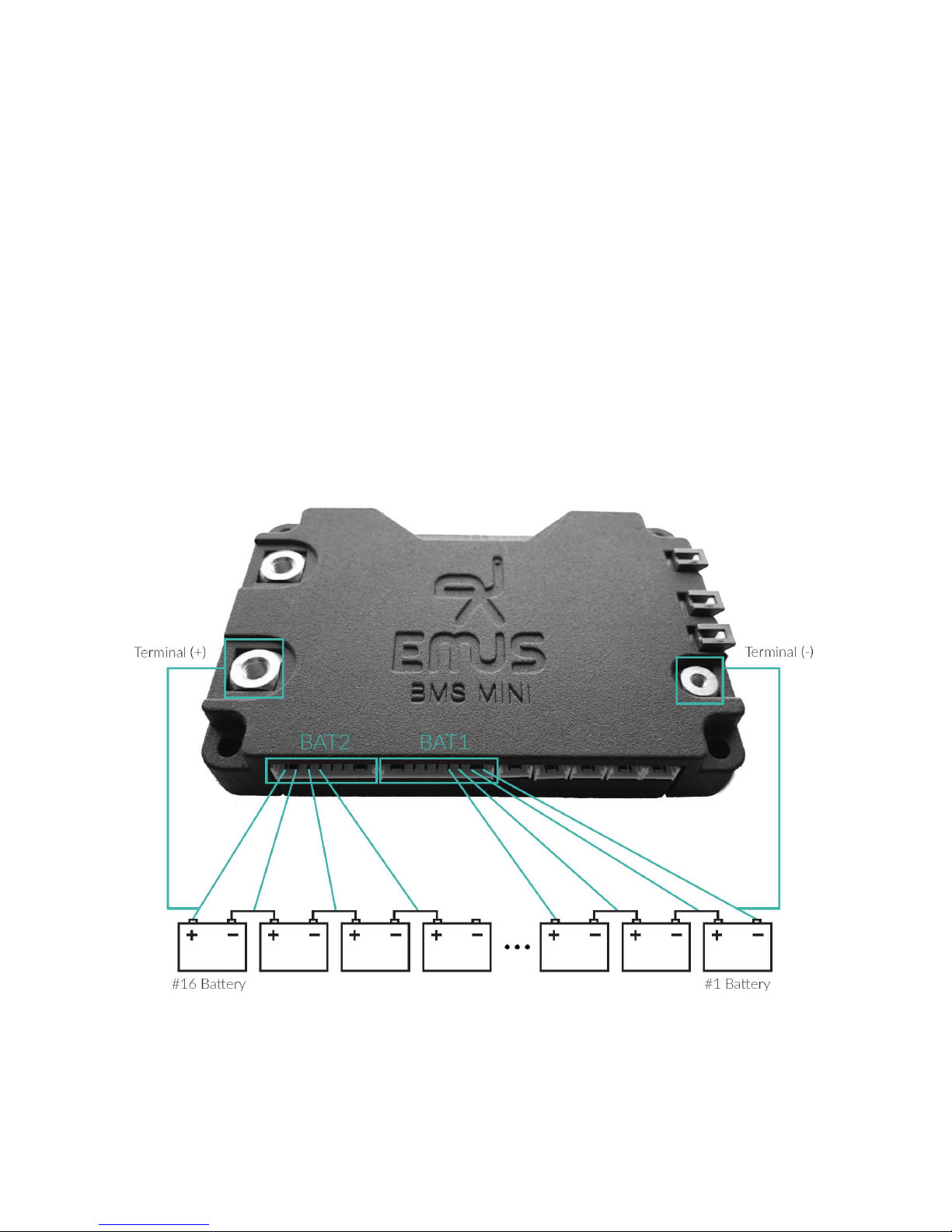
There are two dedicated connectors for battery pack’s power terminals and two for direct connection
with batteries.
In order to safely connect batteries follow these instructions step by step. Also please refer to the
wiring diagram in figure 2.1 for detailed overview of described connections.
1. Connect BMS mini "Terminal (-)" with "-" of #1 Battery;
2. Connect BMS mini "Terminal (+)" with "+" of highest battery cell in a string;
3. Connector BAT1 has 9 pins and connects first 8 batteries of a battery pack. Connector BAT2
has 8 pins and connects remaining 8 batteries. Batteries must be connected to connectors
from right to left side in a sequence from lowest potential to the highest potential.
Note! When connecting less than 16 battery cells all unused wires must be connected to the
highest battery cell in a string.
Figure 2.1: Battery connection diagram
Example 24 V system
In this example 7 Lithium Ion (Li-ion) battery cells are used to reach nominal total voltage of 25.9
V. In order to connect 7 battery cells only 8 pins of BAT1 connector is used. Remaining 9th pin
and all BAT2 connector pins must be tied to positive potential of #7 Battery. Refer to figure 2.2.
6
Page 8
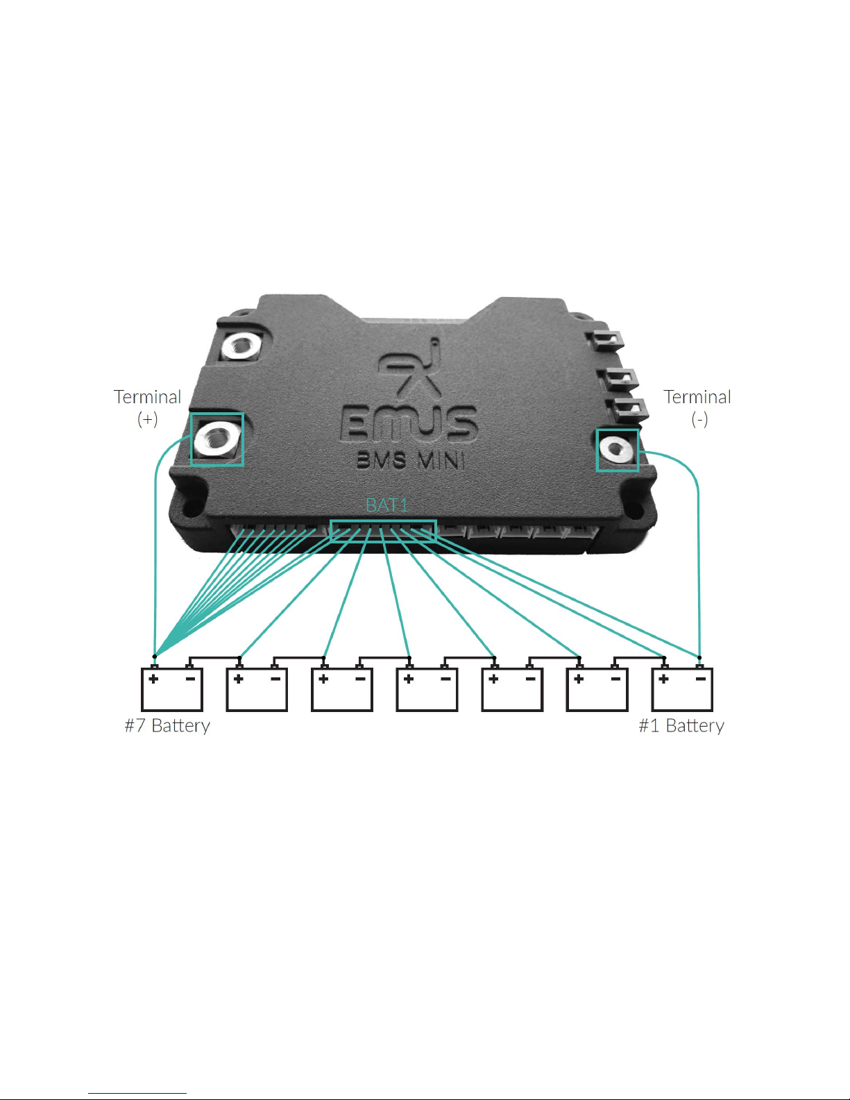
Wiring steps:
1. Connect BMS mini "Terminal (-)" with "-" of #1 Battery;
2. Connect BMS mini "Terminal (+)" with "+" of #7 Battery;
3. Connect wires from BAT1 connector to battery cells in a series. From lowest (#1) to highest
(#7) potential.
4. All remaining (unused) wires from BAT1 and BAT 2 connectors must be connected to positive
potential of #7 Battery;
Figure 2.2: Example system 24 V (7 battery cells)
Example 36 V system
In this example 10 Lithium Ion (Li-ion) battery cells are used to reach nominal total voltage of 37.0
V. In order to connect 10 battery cells 9 pins of BAT1 connector and 2 pins of BAT2 connector must
be used. Remaining 6 pins of BAT2 connector must be tied to positive potential of #10 Battery.
Refer to figure 2.3.
Wiring steps"
1. Connect BMS mini "Terminal (-)" with "-" of #1 Battery;
2. Connect BMS mini "Terminal (+)" with "+" of #10 Battery;
7
Page 9
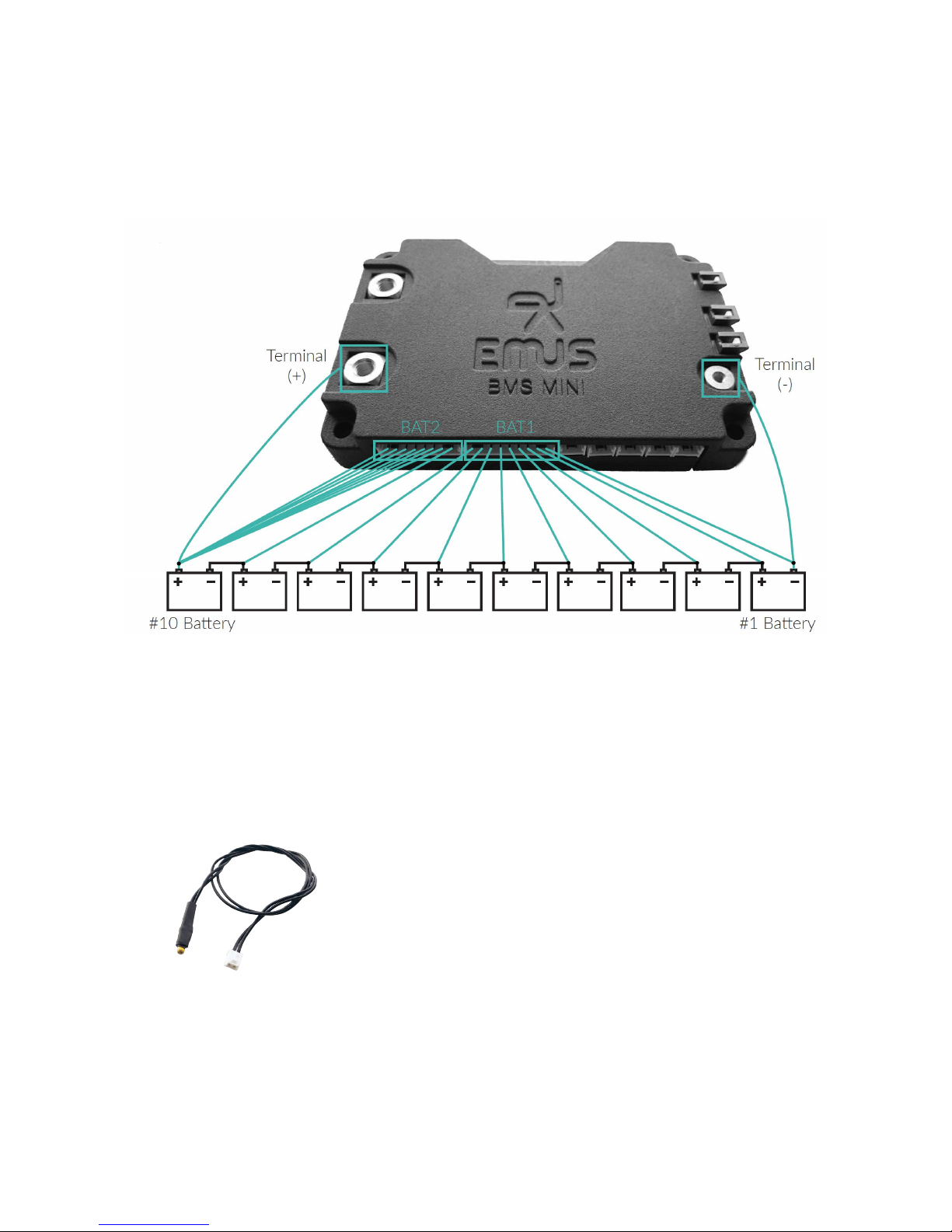
3. Connect wires from BAT1 and BAT2 connectors to battery cells in a series. From lowest (#1)
to highest (#10) potential.
4. All remaining (unused) wires from BAT2 connector must be connected to positive potential
of #10 Battery;
Figure 2.3: Example system 36 V (10 battery cells)
2.2 Connecting temperature sensors
On the bottom of the BMS mini (refer to figure 2.5) there are five 2-pin connectors dedicated to
external temperature sensors. External temperature sensor is shown in a Figure 2.4.
Figure 2.4: External Temperature
Sensor
Temperature sensors are easy to set-up, because they are
designed to support "Plug and Play" functionality. You just
simply need to connect provided external temperature sensors
to any of these slots and no further configuration is needed.
Sensors are hot-swappable meaning installation can be performed while system is powered. Use the same steps when
you need to remove or replace these sensors. In Figure 2.5 is
it shown that external temperature sensors can be mounted on
battery cells or between them.
8
Page 10
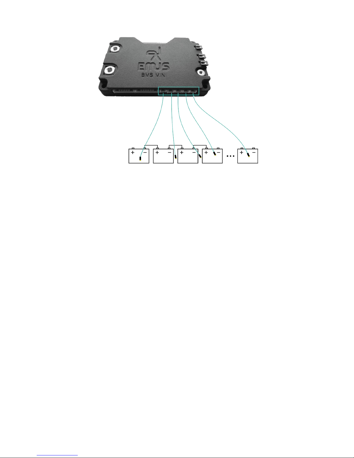
Figure 2.5: External Temperature Sensor installation diagram
2.3 Charger installation
Charging process control is one of the most important tasks that a battery management system
must perform to ensure safe lithium battery operation, therefore it is very important to correctly
select and connect a charging device in order allow EMUS BMS mini to control it. The selection
of a particular charging device should be done considering various aspects of the application, yet its
output parameters are the most important from the battery management system’s point of view. The
maximum charger’s output voltage should be slightly higher than the cell charge voltage specified
in the cell specification sheet multiplied by the number of cells connected in series. The maximum
charger’s output current should not exceed the maximum charging current specified in the same
specification sheet. Correct connection of different charging devices types supported EMUS BMS
mini is described in the following chapters.
2.3.1 Non-CAN based charger
Non-CAN charger can be integrated with EMUS BMS mini in 2 different scenarios: using additional
components to control the charger or without control. Main differences of these two scenarios are
described below:
1. When using Non-CAN charger without control BMS cannot perform charger switching, also
battery pack does not reach full potential of balanced cells.
2. When using Non-CAN charger with additional components for control, BMS can perform
charger switching, and total battery cell balance is reached, but with relatively slower balancing
process.
Scenario 1 (uncontrolled Non-CAN charger)
In the following figure 2.6 a system using uncontrolled Non-CAN charger is presented. In this
scenario Non-CAN charger is directly connected to the battery pack. BMS has no control over
charger’s output voltage or current. Therefore, when the battery pack is nearly fully charged these
events will happen: because this type of charging is uncontrolled, balancing is not efficient and
9
Page 11
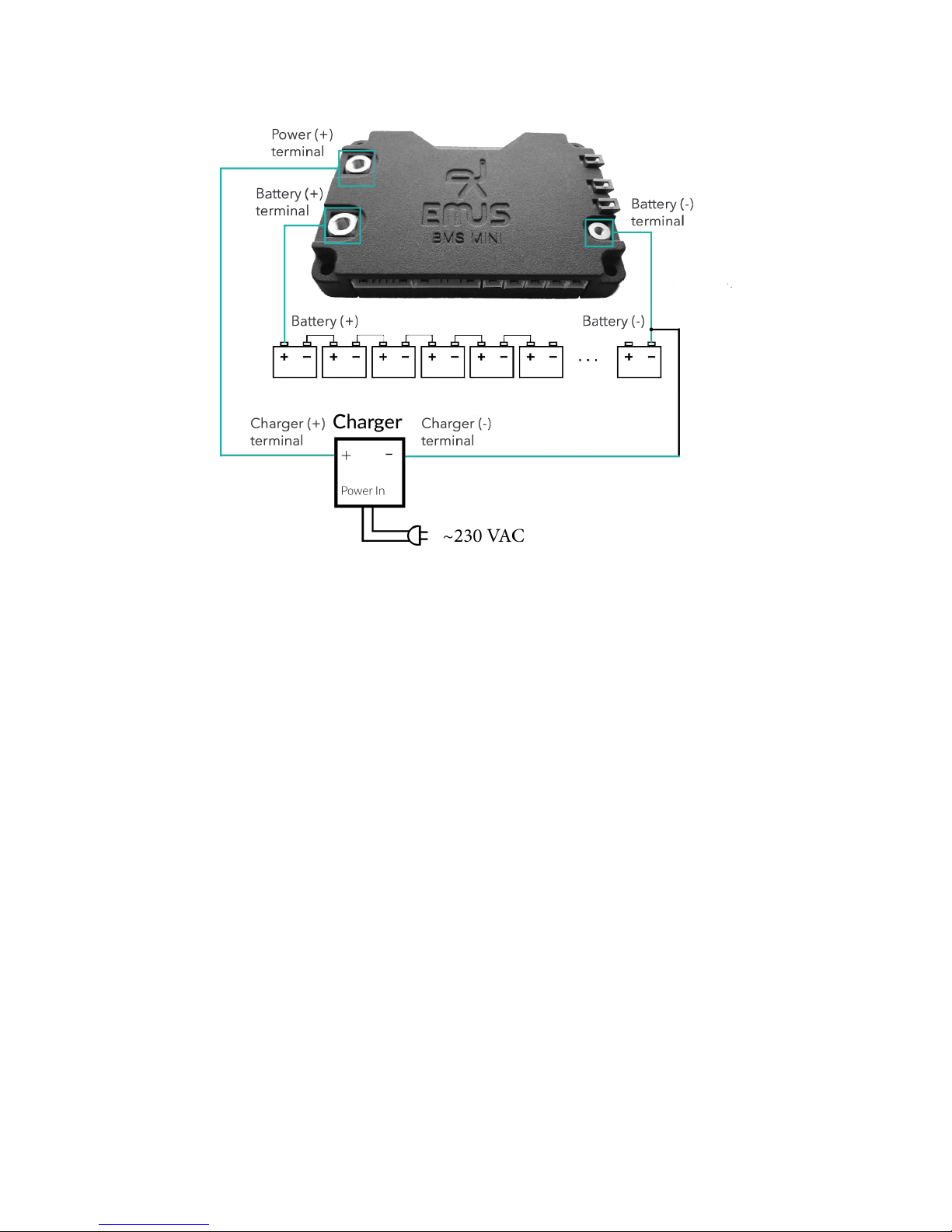
Figure 2.6: Uncontrolled Non-CAN charger installation diagram
eventually one of battery cells will be charged to its maximum voltage and when it tries to rise even
more BMS will trigger ’Over-voltage’ protection and internal contactor will disconnect a charger,
which will finish charging process. For this set-up firstly connect battery to BMS mini: connect
"Battery (-)" to "Battery (-) terminal" and "Battery (+)" to "Battery (+) terminal" using power
cables. Now charger can be connected: using power cables connect "Charger (-) terminal" to
"Battery (-)" and "Charger (+) terminal" to "Power (+) terminal".
10
Page 12
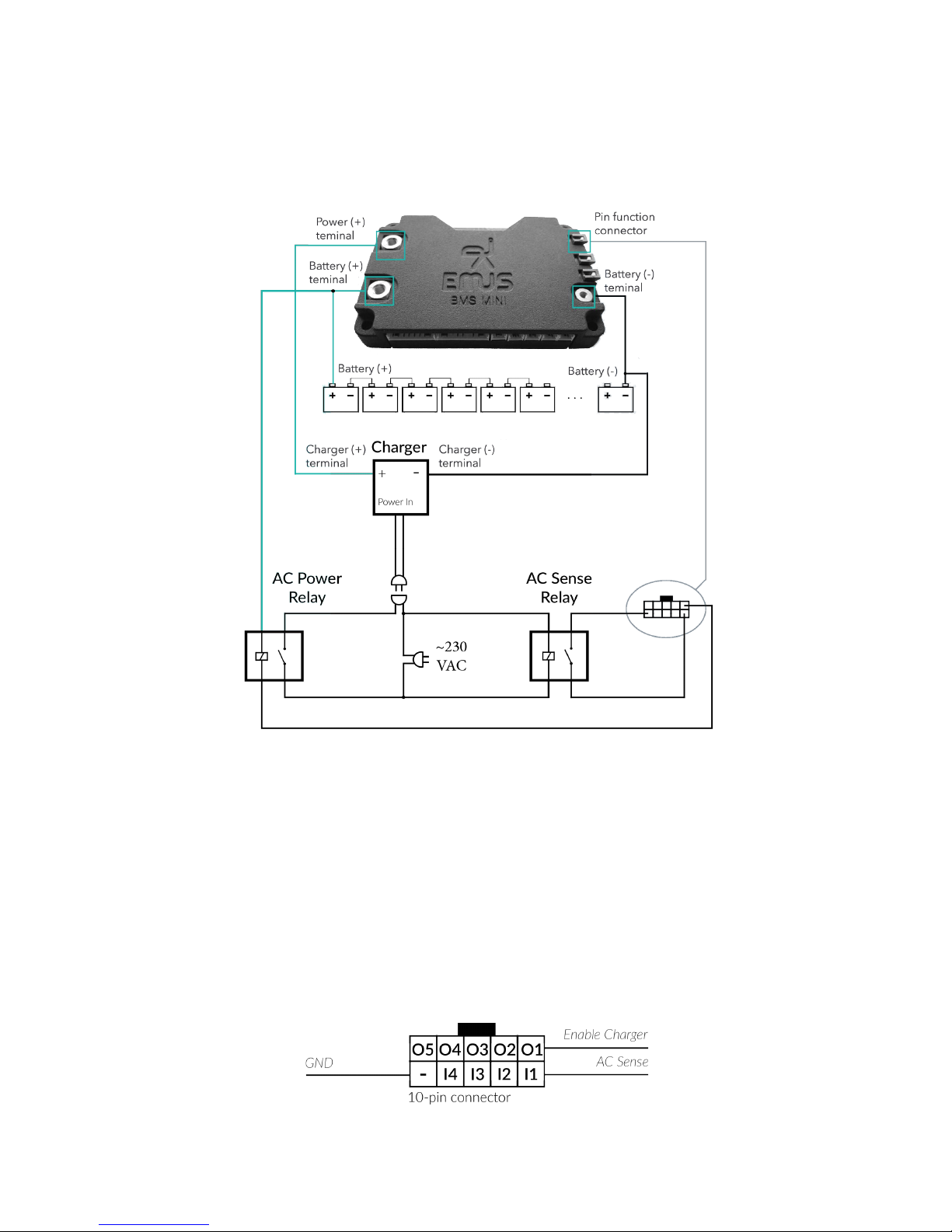
Scenario 2 (controlled Non-CAN charger)
In the following figure 2.7 a system using controlled Non-CAN charger is presented. In this scenario
Non-CAN charger is directly connected to the battery pack and controlled using low and high power
relays. For this set-up firstly connect battery to BMS mini: connect "Battery (-)" to "Battery (-)
Figure 2.7: Controlled Non-CAN charger installation diagram
terminal" and "Battery (+)" to "Battery (+) terminal" using power cables. Now charger can be
connected: using power cables connect "Charger (-) terminal" to "Battery (-)" and "Charger (+)
terminal" to "Power (+) terminal". Now we will setup control/indication components. Low power
AC Sense Relay of type NC (normally closed) should be connected in series to the AC Mains, which
purpose is to signal whenever power is present. Connect one output of this relay to ’I1’ pin of
pin function connector, which is displayed in figure 2.8. Other output connect to ’-’ pin of the
safe 10-pin connector. Use high power relay to connect Non-CAN charger as shown in figure 2.7.
Connect one power relay input to "Battery (+) terminal" and another one to ’O1’ pin of pin function
connector. Wiring is completed what is left is to enable these "AC Sense" and "Enable Charger"
Figure 2.8: 10-pin Pin Function connector
11
Page 13
pin functions on a mobile application. Refer to section 9.1 for how to download mobile application.
Navigate to Configuration → Pin Functions and enable "AC Sense" function for pin "GPI1" and
"Enable Charger" for "GPO1". Dimensioning and selection of the electromechanical contactor and
other necessary components should be done according to the requirements of the particular system,
and is out of the scope of this document.
Note! If voltage of the battery pack is greater than supply voltage of AC Power Relay, additional
DC/DC converter should be used.
2.3.2 CAN based charger
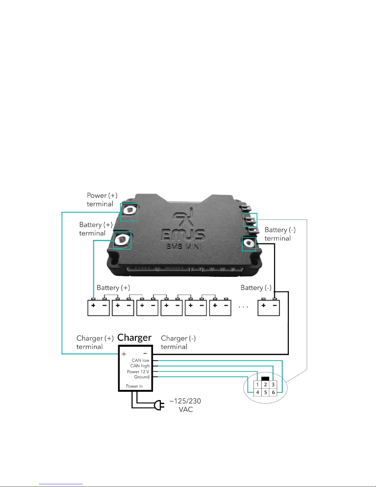
Provided wiring connection between BMS mini and CAN Charger in figure 2.9 is only for reference,
and should be done according to the general rules of correct CAN bus setup that are described in
section 4.2. CAN charger is directly connected to a battery, but its control is performed over CAN
Bus. Wiring diagram is shown in figure 2.9. Firstly connect battery to BMS mini: connect "Battery
(-)" to "Battery (-) terminal" and "Battery (+)" to "Battery (+) terminal" using power cables. Now
charger can be connected: using power cables connect "Charger (-) terminal" to "Battery (-)" and
"Charger (+) terminal" to "Power (+) terminal".
Figure 2.9: CAN charger wiring diagram
What is left is to wire CAN interface according to a CAN connection pinout shown in a figure 2.10.
12
Page 14
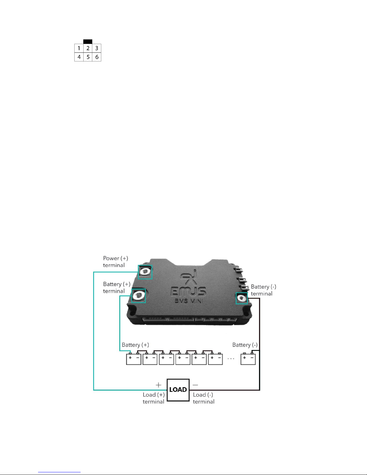
Figure 2.10: CAN connector
1. Power supply (+12 V)
2. 120 Ω terminator jumper
3. CAN high signal
4. Ground (GND)
5. 120 Ω terminator jumper
6. CAN low signal
Connect 1st pin to power supply of 12 volts, 4th pin to ground terminal (0 volts). CAN uses two
dedicated wires for communication, which are called CAN high and CAN low. Connect those with
your charger CAN Bus interface or with common CAN Bus communication wires. Additionally BMS
mini provides integrated CAN Bus terminating resistor. In order to use it just short 2nd and 5th
pins together, and 120 Ω terminating resistor would be applied to CAN Bus.
2.4 Load installation
On the left side of EMUS BMS mini (refer to figure 2.11) there are 2 power terminals: one is
dedicated to connect battery and another one is for connecting load. Before connecting any device
(load) you must power-up the BMS mini itself. Therefore, connect battery pack power cables
to BMS mini: "Battery (-)" with "Battery (-) terminal" and "Battery (+)" with "Battery (+)
terminal" and BMS should be up and running. Make sure that device (load) will not draw
current immediately connected: power switch is turned off or in electric vehicle case throttle
is released. Firstly connect "Load (-) terminal" to "Battery (-)" and then "Load (+) terminal" to
"Power (+) terminal" using power cables.
Figure 2.11: Load installation diagram
BMS mini supports "Contactor pre-charge" (refer to section 3.5), meaning BMS internal contac-
tor will gently, without putting stress to internal components connect devices with load capacitance.
13
Page 15

3 Core BMS functionality
3.1 Battery Monitoring
3.1.1 Voltage Monitoring
Battery cell voltage can be measured from 1.000 V to 4.500 V. Before final evaluation each battery
cell is simultaneously sampled 32 times with a precision of 3 digits after decimal point in order to
get the most precise and stable value. These measurements are performed at 32 Hz (31.25 ms)
frequency. Settings for "Minimum Cell Voltage" and "Maximum Cell Voltage" parameter values are
located in EMUS Mobile Application, Configuration page → Battery tab.
3.1.2 Current Measurement
EMUS BMS mini dual range integrated current sensor is an analog, hall-effect based current measurement device. The hall-effect measurement method also provides an inherent galvanic isolation
between sensor ant the conducting part.
There are two functionally identical types of the EMUS BMS mini dual range current sensor:
internal and external. Internal current sensor works in a range from −75A to +75A and has
current update rate of 1 kHz. External current sensor parameters depend on its sub-type. Current
measurements have an accuracy of 1 digit after decimal point (e.g. 15.7 A) for all types of current
sensors.
Table 3.1: External current sensor operating current range
From, A To, A
−200A +200A
−800A +800A
Table 3.2: External current sensor current update rate
Communication type Update rate, Hz
CAN 100
LIN 10
Either internal or external current sensor module continuously measures the analog signals given
by current sensors using a high sample rate analog-to-digital converter peripheral, and periodically
stores averaged measurement results for further processing. The averaging is needed in order to
mitigate the effects of thermal, quantization and other noises. The most recent results of the
measurement process are taken, verified for validity, and used for calculating the momentary battery
current value.
Each external Current Sensor is available with CAN or LIN communication interface. Current
Sensor based on CAN communication is recommended when power consumption is not an issue and
high sampling-broadcasting rate is needed. On the other hand if power consumption is an issue then
Current Sensor based on LIN communication is recommended, because it requires significant lower
power for operation and communication.
14
Page 16

In order to install external current sensor connect it to LIN / CAN Bus connector. If direct connection
is not possible, a LIN / CAN Bus splitter should be used in order to interconnect additional bus
node.
3.1.3 Temperature measurement
External temperature sensors are able to measure temperatures from -40 °C up to 150 °C. Measurements are performed 2 times a second (T = 0.5s). There are also several internal temperature
sensors that measure temperature of internal device components. All of them are stationary and
cannot be disconnected or altered.
Real time external and internal temperature readings can be found in Status page → Battery tab.
Temperature readings are split in to two separate charts. Each chart displays aggregated minimum,
maximum and average values of temperature.
3.2 State of Battery
3.2.1 Charge estimation
State of Charge estimation in EMUS BMS mini is mainly based on the coulomb counting technique.
The coulomb counting is done in sync with the current update process every newly determined
momentary current value is multiplied by the update period, and the result, is accumulated as
Battery Charge value (in Ah). This value is later compared to ”Capacity” configuration parameter
value in order to determinethe SoC expressed in percentage.
3.2.2 Health estimation
TBD
3.3 Charging process
BMS controls charging process and regulates output current of the charging device according to
feedback of measured battery parameters. It ensures that the battery is charged safely and the
battery cell voltages are correctly balanced after the charging process is finished. Regardless of the
charging device type, charging process is divided into six stages:
1. "Pre-Heating" stage is entered when the minimum temperature value of all system temperature sensors is lower than the value of "Minimum Charging Temperature" parameter, meaning
that the battery is too cold to be safely charged. Therefore during this stage BMS attempts
to warm it up by activating "Heater" function which can be enabled using pin functions. This
function is indended for switching third-party heating devices on and off.
2. "Pre-Charging" stage is entered then the minimum cell voltage is lower then Pre-Charge
Threshold" parameter value. This condition is met only when the battery cell is deeply discharged, therefore during this stage the battery is charged with a reduced current in order to
avoid heat development inside the battery cells due to their increased internal resistance.
3. "Charging" stage is entered if the maximum battery cell voltage is less than "Maximum
Cell Voltage" parameter value and no other stage conditions are met. This indicates that no
special precautions are needed in order to safely charge the battery, therefore during this stage
the battery is charged with the highest possible current. Highest current depend on charging
device and Maximum Charging Current" parameter value.
15
Page 17

4. "Balancing" stage is entered when the maximum cell voltage is more than or equal to
the "Maximum Cell Voltage" parameter value. The balancing threshold is by default equal
to "Maximum Cell Voltage” parameter value as well. When balancing condition is active
BMS starts to divert the charging current for each battery cell through shunt resistors in
attempt to prevent the cell voltages from rising further. At the beginning of this stage the
charging device is kept on until the maximum cell voltage starts to exceed the ”Maximum
Cell Voltage” parameter value by more than 10 mV, even though the corresponding battery
cell is being balanced. Then the charging device is turned off and the balancing threshold
is set to "Minimum Cell Voltage" plus the value of ”Voltage Disbalance” parameter (but
not higher than ”Maximum Cell Voltage” parameter value) in order to dissipate the energy
difference between cells as heat. At the end of this phase the difference between minimum
and maximum cell voltages is lower than the ”Allowed Disbalance” parameter value, then this
stage is over, otherwise the charging device is turned on again and this process repeats.
5. "Finished" stage is entered whenever the "Balancing Stage" is completed. It indicates that
the charging process is complete, therefore during this stage the charging device, regardless if
its type, is disconnected from the battery pack by opening the charging contactor.
6. "Error" stage is entered if one of the several pre-defined critical conditions are met during
he charging process.
Each charging stage persists until its entering condition is valid. The order in which charging
stages take place is not strictly defined. Naturally, they follow the order as they are listed above,
but it can vary depending on the situation. For safety reasons BMS does not allow to change any
configuration parameters during the charging process.
3.3.1 Using Non-CAN charging device
Basic charging devices that do not have any EMUS BMS compatible interface for controlling their
output current and voltage (also referred to as Non-CAN charging devices) are controlled by utilizing
a special algorithm to turn them on an off using a switching device that is driven by a general purpose
output pin mapped with ”Charger Enable” pin function. The BMS acknowledges the connection
and disconnection of such charging device whenever a corresponding high/low signal is detected on
a general purpose input pin mapped with ”AC Sense” function;
3.3.2 Using CAN charging device
Charging devices that are equipped with a CAN interface (or simply CAN chargers) are controlled by
sending the requested output voltage and current values to them in a CAN message using a protocol
that is specific to a particular charger.
Currently EMUS BMS mini officially supports the following CAN chargers:
• Elcon
BMS acknowledges that a CAN charger is connected when it receives a particular CAN message
from a charger. Depending on the charger model, the charger transmits this message either by
itself (periodically), or as a response to a requested CAN message from BMS. Disconnection is
acknowledged if BMS does not receive any CAN message from the charger for more than 15 seconds.
Consequently, the "Pin Function: AC Sense" has no meaning when using this type of charging device.
16
Page 18

3.3.3 Configuration
All configurations for charging can be made using EMUS mobile application. These configurations
are located in Configuration page → Charging tab and consists of "Voltage Settings" and "Current
Settings".
Voltage Settings group has the following parameters:
• Balancing voltage threshold — battery cells voltage balancing is enabled on battery cells,
which voltage is higher than this threshold and out of "Voltage disbalance" range related to
other battery cells.
• Recharging voltage threshold — battery pack charging is reinitiated when "Minimum Cell
Voltage" is below this threshold.
• Voltage disbalance — maximum allowed voltage difference between current minimum and
maximum battery cell voltages.
Current Settings group has the following parameters:
• Maximum charging current (continuous) — maximum allowed continuous charging current.
• Maximum discharging current (continuous) — maximum allowed continuous discharging cur-
rent.
3.4 Battery Protections
During charge and discharge EMUS BMS protects the battery cells from an operation beyond
certain limits of its parameters: voltage, current, temperature. Description and configuration for
each protection is described in the following chapters.
3.4.1 Cell Over-Voltage Protection
Cell Over-voltage protection prevents the battery cells from being overcharged during regenerative
process, and is activated if the voltage of at least one of the battery cells is above the threshold set
by "Maximum Cell Voltage". When protection is triggered integrated/external contactor disconnects
charger from the battery pack to prevent any damage to the battery cells. When voltage of the
battery cells, which triggered protection, drops below this voltage threshold parameter, contactor
connects charger back and system recovers from the triggered protection.
3.4.2 Cell Under-Voltage Protection
Cell Under-voltage protection prevents the battery from being discharged further if the voltage of at
least one of the battery cells is below the threshold set by the "Minimum Cell Voltage" parameter.
When protection is triggered integrated/external contactor disconnects load (motor) from the battery
pack to prevent deep depletion of the battery cells. When charger is connected and prepared to
charge the battery pack, contactor connects load back. System recovers from this protection when
voltage of battery cells, which invoked this protection rise above mentioned threshold parameter.
17
Page 19

3.4.3 Charge Over-Current Protection
Charge Over-Current protection disconnects charger contactor or disables charger itself if pin function
"Charger enable" is activated whenever the measured charge current is above the threshold set by
the corresponding "Activation Threshold” parameter value, thus preventing the high currents during
regenerative processes from potentially damaging the battery cells.
3.4.4 Discharge Over-Current Protection
Discharge Over-Current protection is activated if the measured discharge current is above the threshold set by the corresponding ”Activation Threshold" parameter value, thus preventing the battery
from being discharged at a rate that is higher than specified by the battery cell manufacturer.
3.4.5 External Over-Temperature Protection
External Over-Temperature protection prevents the battery from being operated when the temperature measured by one of the external temperature sensors is above "Activation threshold" parameter
value, which may indicate an unexpected heat development somewhere in the battery.
3.4.6 External Under-Temperature Protection
External Under-Temperature protection prevents the battery from being operated when the temperature measured by one of the external temperature sensors is below "Activation threshold" parameter
value, which indicates that environment is too cold for battery exploitation.
3.4.7 Internal Over-Temperature Protection
Internal Over-Temperature protection prevents the device from being operated under high temperature, which could build-up if heat dissipation is not performed well due to unexpected heat
development inside device. Protection is activated when value of measured internal temperature is
above "Activation Threshold" parameter value.
3.4.8 Configuration
Settings that regulate the behavior of the protections can be found in the Configuration page →
Protections tab and consists of six sets of parameters for each different protection type. Each set
contains five of the following parameters:
• Enable/Disable protection;
• Enable deactivation
• Activation Threshold;
• Deactivation Threshold;
• Activation Delay;
• Deactivation Delay.
All thresholds and delays are configured independently for each protection. All protections are
enabled by default, but can be disabled individually if necessary."Activation Threshold" and "Deactivation Threshold" parameters, allow to create hysteresis between activation and deactivation
values. BMS is forced to tolerate activation condition for as long as corresponding "Activation
Delay" parameter value before activating the protection. Likewise, the deactivation condition has
18
Page 20

to persist for as long as the corresponding "Deactivation Delay" parameter value for the protection
to be deactivated. When Enable deactivation is activated, this protection will not recover even if its
recovery conditions are met, therefore protection must be reset manually.
The possible value range for the "Activation Delay" and "Deactivation Delay" parameters is from
0 to 600 s with a step of 1 millisecond.
The possible and recommended value range for the ”Activation Threshold" and "Deactivation
Threshold" parameters depend on the corresponding protection type:
• For "Cell Under-Voltage" and "Cell Over-Voltage" protections both parameters can have a
value from 2.000 to 4.500 V. However recommended values should be set according to discharge and charge cut-off voltage values that are defined in the manufacturer provided specification sheet of the battery cells used in the battery pack;
• For "Discharge Over-Current" and "Charge Over-Current" protections the range of possible
values of the "Activation Threshold" parameter is from 0.1 to 800.0 A, depending on the
selected EMUS contactor model;
• For "External Over-Temperature" parameter can have a value from 20 to 155 °C. Recom-
mended value is 60 °C.
• For "External Under-Temperature" parameter can have a value from -40 to 10 °C. Recommended value should be set according to minimum operating temperature value that is defined
in the manufacturer provided specification sheet of the battery cells.
The optimal values for these parameters, as well as the necessity of each type of protection should
be assessed according to the design and requirements of the system in which EMUS BMS is used,
or determined experimentally.
3.5 Contactor pre-charge
In a lot of different applications the battery that is managed by EMUS BMS connects to a load that
has a substantial input capacitance. In such case, it is often desirable to limit the high in-rush current
that occurs when the main contactor is closed in order to reduce stress to the internal components
of the load device and prevent the contactor from welding. For that reason, EMUS BMS mini offers
a very straightforward contactor pre-charge feature (not to be confused with “Pre-Charging stage”
that occurs during the charging process).
This feature works by constantly sampling voltage on contactor from load device side while slowly
closing contactor providing small current to pass through. When voltage difference between battery
and load device input capacity is less than 10%, contactor is fully closed.
19
Page 21
4 Data interfaces
BMS mini uses CANopen protocol for communications through listed interfaces (except LIN). Device
has it’s object dictionary supporting various parameters viewing and configuring. Each interface
caries CANopen packets and has access to all available device features. All interfaces can be
accessed asynchronously and independently to each other.
4.1 Wireless smartphone connectivity
2.4 GHz integrated wireless interface is designed to connect with smart-phones and PCs supporting
the same wireless technology. "EMUS BMS mini" application has to be installed in order to connect
BMS mini device used for information display and configuration. Smartphone acts as a CANopen
client and communicates through EMUS BMS mini object dictionary. Interface works as serial
transmission channel and transfers standard CANopen packets back and forth. Wireless interface
also enables features like discovering currently enabled BMS mini devices in range and displays their
customizable names and serial number for easier identification. It’s worth notice that only one
wireless client (e.g., smart-phone) can be connected at the time. BMS mini will not be discoverable
until primary device disconnects. However, other interfaces will still be available.
4.2 CAN
The CAN bus has be widely adopted in industrial, automotive, and instrumentation applications
due to the inherent strengths of its communication mechanisms, however its reliability will be compromised if it is not set up correctly. CAN-equipped Emus BMS components are designed to be
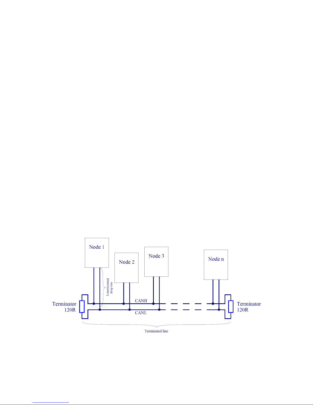
used in high-speed CAN networks, such as the one specified by the ISO 11898-2 standard. This
standard defines a single line structure network topology in which the bus lines are terminated at
their furthest ends by a single termination resistor, as shown in figure 4.1.
Figure 4.1: High-speed CAN network specified in ISO-11898-2 standard
The maximum total bus length and maximum lengths of a single unterminated drop line and all
unterminated drop lines together of a CAN network to which Emus BMS components are connected
are presented in the Table 4.1. Maximum total bus length is essentially limited by propagation
20
Page 22

delays of the used CAN transceiver and transmission line, and CAN bit timing settings used in CANequipped Emus BMS components. In practice however, lengths with which CAN communication is
reliable may be lower due to use of low grade cables or a high number of connected nodes, therefore
it is recommended to choose the length with the maximum possible reserve when designing the CAN
network. It is also important to note that unterminated drop lines contribute to the total bus length
and thus limit the maximum length of the terminated line.
Table 4.1: Maximum bus line lengths, calculated based on the used CAN bit timing setting, considering
that a twisted-pair cable with a typical propagation delay of 5 ns/m is used. LU- maximum length of a
single unterminated drop line,PLU- maximum length of all unterminated drop lines together.
Baud rate L
U
P
L
U
Max total bus length
1 Mbit/s 2 m 10 m 20 m
800 kbit/s 3 m 15 m 32 m
500 kbit/s 3 m 15 m 45 m
250 kbit/s 6 m 30 m 120 m
125 kbit/s 12 m 60 m 270 m
50 kbit/s 32 m 160 m 770 m
Ideally the topology of the actual CAN network should be as close as possible to a single line
structure, since unterminated drop lines cause signal reflections to occur on the bus, and the longer
they are, the more likely it is for the reflections to continue long enough to cause the node receivers to
misread the signal levels. In practice however, the network is often designed to slightly deviate from
ideal topology for easier installation, yet the both the length of a single drop line and the cumulative
length of all drop lines on the bus should not exceed certain limits, otherwise the reflections may
cause communication errors even though the line is properly terminated. The maximum values of
these lengths in Table 4.1 are calculated based on the bit timing settings used in CAN-quipped
Emus BMS Components, which were chosen according to the recommendations in CiA (CAN in
Automation) 301 standard, and are optimal when nodes from different manufacturers are connected
to the same CAN network.
According to high-speed transmission specification in ISO11898-2 standard, both ends of the
CAN bus must be terminated in order to minimize reflections and ensure that both lines are correctly
returned to a recessive state, because any node on the bus may transmit data. The termination
resistors should match the characteristic impedance of the cable, although the recommended value
is nominally 120W (100W minimum and 130W maximum). There should not be more than two
terminating resistors in the network, regardless of how many nodes are connected, because additional
terminations place extra load on the drivers. ISO-11898-2 standard also recommends not integrating
a terminating resistor into a node but rather using standalone termination resistors. This concept
helps to avoid a loss of a termination resistor if a node containing that resistor is disconnected, and
prevents connecting more than two of them to the bus or locating them at other points in the bus
rather than at the furthest ends.
Maximum number of nodes in a CAN network is limited by their finite differential input resistance
that loads the line and decreases the signal amplitude, therefore it depends on the driving capability
of the used CAN transceiver. The manufacturer of the transceivers used in CAN-equipped Emus
BMS components specifies that it will drive a minimum load of 45W, allowing a maximum of 112
nodes to be connected, given that the differential input resistance of each node on the bus is not
less than 20kW and 120W termination resistor are used.
In order to ensure the robustness and reliability of the CAN network regardless of the conditions
in which it will be used, it is recommended to use a shielded twisted pair cable to implement it.
Due to space saving reasons the CAN interface is populated only on a single connector in all CAN-
21
Page 23

equipped Emus BMS components, therefore they should be connected to the bus either at its ends,
or by branching the bus cable somewhere in the middle. When using the latter method, each wire of
the branch cable, including the shield, should be connected to corresponding wire of the main bus
cable by using a T connector, wire tap splices, or in the worst case, by soldering the wires together
and covering them in heat-shrink tube. The shield should be grounded at a single point only, ideally
as close as possible the output of the power supply that powers the nodes connected to the CAN
network in order to avoid ground loops.
4.2.1 Installation
TBD
4.2.2 Configuration
Current baudrate — 250 kbps
TBD
22
Page 24
5 Remappable GPIO Functions
5.1 Description
BMS mini supports remappable pins, which can be mapped with various different functions during
configuration. The default function of one pin can be remapped onto another pin. These pins are
also further divided into input and output categories. Each pin depending on its category has a
set of standard and special mappable functions. Functions that fall in standard set are intended
for driving relays, indicators, etc., reading or transmitting various logic signals from/to third-party
devices. Functions that fall in special set are intended to control special third-party devices or read
their complex signals.
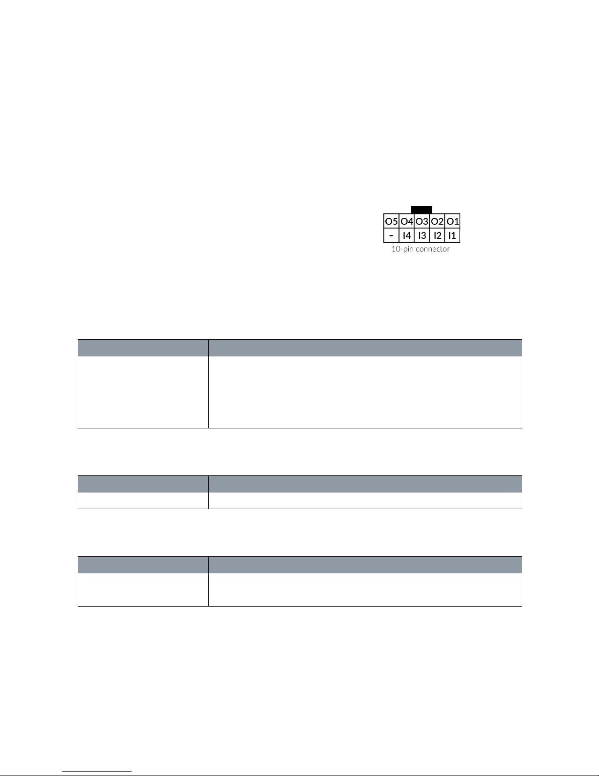
Figure 5.1: Pin function connector pinout
There are 9 remappable pins divided into two
groups: inputs (GPI1 ... GPI4) and outputs (GPO0
.. GPO5) refer to figure 5.1 for detailed overview.
All functions are unique, so they can only be mapped
once, meaning there can only be 1 pin mapped with
particular function at a time. Tables 5.1, 5.2, 5.3 and
5.4 contains all currently supported pin functions.
Table 5.1: List of standard set input functions
Pin function Description
Ignition Used for reading ignition state. When active BMS enables additional fea-
tures and/or changes function priorities
AC Sense Used for sensing when AC Mains is present to supply power for Non-CAN
charger
Protection Reset Used when user wants to clear all occurred protections
Table 5.2: List of special set input functions
Pin function Description
None -
Table 5.3: List of standard set output functions
Pin function Description
Charging indication Used for indicating charging process
Protection indication Used as indication when protection occurs
Figure 5.2 shows possible ways how to configure input and output pins.Each input pin function
can configure its input to accept voltage higher than 3.3 volts, meaning when high voltage is applied
to input it would read high level signal, and when no voltage is supplied it would read low level
signal (refer to 5.2 (a)). Input pin function can also be configured in a way that no external voltage
would be needed. In this case when input is connected to ground it would read low level signal and
when it is left floating input would read high level signal (refer to 5.2 (b)). All output pin functions
are configured the same to use ’open-drain’ technique. Note! V
max
<= 70 V.
23
Page 25
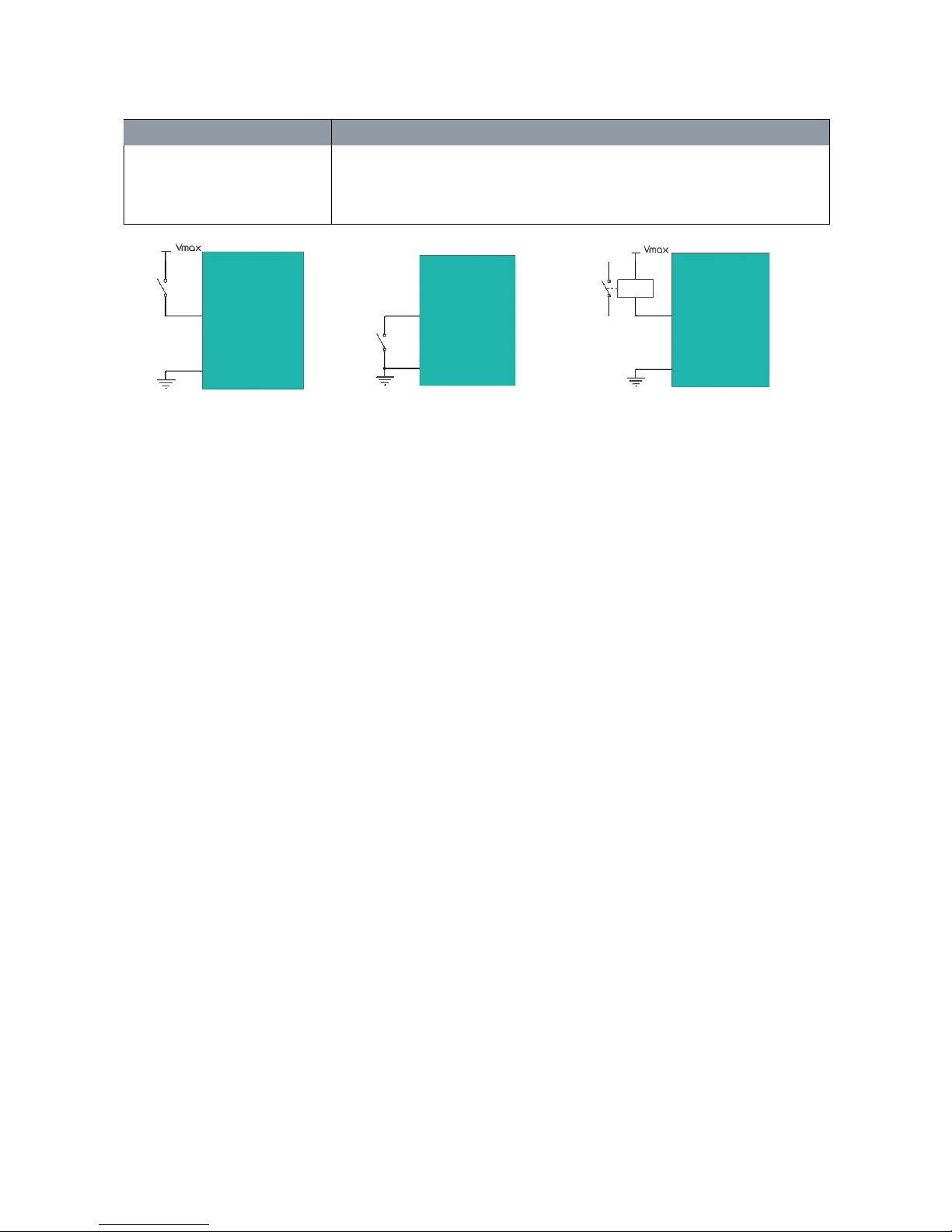
Table 5.4: List of special set output functions
Pin function Description
State of Charge indication Used to generate pulse-width-modulated signal from 0 volts to total voltage
of Battery pack. When driving an analog fuel gauge the duty cycle of the
generated PWM signal is directly proportional to the estimated battery state
of charge
a
b
c
Figure 5.2: Input and output pin configuration: a) High voltage sensing input, b) Ground sensing input,
c) High voltage output
5.2 Configuration
Using EMUS BMS mini mobile application each pin can be configured individually and effortless:
• In the main menu locate Configuration page → Pin Functions tab;
• There will be all available input and output pins with programmable functions. Select a pin
which function you would like to change.
• In the resulting drop-down window a list of all currently available functions for this pin will be
listed. Simply select new function and it will be automatically configured and enabled.
• Each pin function has additional parameters: e.g. functionality inversion, input sensing type...
Therefore it can be additionally configured when needed.
Note! Pay attention to input pin function sensing type. If input function is configured with Voltage
sensing it means pin is sensing high voltage, and if configured as Ground sensing - pin is sensing
ground (0 V). When input pin is configured for ground sensing, and high voltage is applied it will
result in damaging the interior components of this input pin.
24
Page 26

6 Analytics
6.1 Statistics
For diagnostic purposes, system keeps track of various pre-defined battery and BMS operation statistics and stores them internally. Each statistic, depending on its type, can consist of a corresponding
main value, additional value, and a timestamp. A list of all statistics is provided in Table 6.1.
Table 6.1: List of statistics and their descriptions
ID Statistic Description
1 Total discharge The total amount of charge transferred out of the battery in Ah
(or kAh if normal range has been overflowed).
2 Total charge The total amount of charge transferred into the battery in Ah (or
kAh if normal range has been overflowed).
3 Total discharge energy* The total amount of energy transferred out of the battery in Wh
(or kWh if normal range has been overflowed).
4 Total charge energy* The total amount of energy transferred into the battery in Wh (or
kWh if normal range has been overflowed).
5 Total discharge time* The total amount of time when negative (discharge) current was
measured is seconds (or hours if normal range has been
overflowed).
6 Total charge time* The total amount of time when positive (charge) current was
measured in seconds (or hours if normal range has been
overflowed).
8 Max Discharge Current The highest recorded discharge current value. This statistic also
contains the timestamp of when the value was recorded.
9 Max Charge Current The highest recorded charge current value. This statistic also
contains the timestamp of when the value was recorded.
10 Min Cell Voltage The lowest recorded cell voltage. Additionally contains the cell
number and timestamp of when this value was recorded.
11 Max Cell Voltage The highest recorded cell voltage. Additionally contains the
corresponding cell ID and timestamp of when this value was
recorded.
12 Max Cell Voltage Difference The highest recorded difference between cell voltages.
Additionally contains the corresponding minimum and maximum
cell voltages, ID of the cell with minimum voltage, and timestamp
of when these value were recorded.
13 Min Pack Voltage The lowest recorded battery pack voltage. Additionally contains
timestamp of when this value was recorded.
14 Max Pack Voltage The highest recorded battery pack voltage. Additionally contains
timestamp of when this value was recorded.
15 Min external temperature The lowest recorded external temperature. Additionally contains
the corresponding sesnor ID and timestamp of when this value
was recorded.
16 Max external temperature The highest recorded external temperature. Additionally contains
the corresponding sensor ID and timestamp of when this value
was recorded.
17 Max external temperature difference The highest recorded difference between temperature of sensors.
Additionally contains timestamp of when this value was recorded.
18 Under-voltage protection count The number of times Under-Voltage protection has been
activated. Additionally contains the timestamp of the last
occurrence.
25
Page 27

19 Over-voltage protection count The number of times Over-Voltage protection has been activated.
Additionally contains the timestamp of the last occurrence.
20 Discharge over-current protection
count
The number of times Discharge Over-Current protection has been
activated. Additionally contains the timestamp of the last
occurrence.
21 Charge over-current protection count The number of times Charge Over-Current protection has been
activated. Additionally contains the timestamp of the last
occurrence.
22 Cell Over-Temperature protection
count
The number of times Over-Temperature protection has been
activated. Additionally contains the timestamp of the last
occurrence.
25 Pre-heat stage count The number of time the "Pre-Heating" stage of the charging
process has been entered.
26 Pre-charge stage count The number of time the "Pre-Charging" stage of the charging
process has been entered.
27 Charging stage count The number of time the "Charging" stage of the charging process
has been entered.
28 Balancing stage count The number of time the "Balancing" stage of the charging process
has been entered.
29 Charging finished count The number of time the "Charging Finished" stage of the charging
process has been entered.
30 Charging error occurred The number of time the "Charging Error" stage of the charging
process has been entered.
32 Charge restarts count The number of times the charging process automatically restarted
when maximum cell voltage dropped below "Recharge Voltage"
parameter value.
33 Over-Temperature protection count The number of times Over-Temperature protection has been
activated. Additionally contains the timestamp of the last
occurrence.
34 Min Internal Temperature The lowest recorded internal temperature. Additionally contains
timestamp of when this value was recorded.
35 Max Internal Temperature The highest recorded internal temperature. Additionally contains
timestamp of when this value was recorded.
26
Page 28

6.2 Events
During operation, BMS keeps a log of the most recent events internally. It consists of 128 entries,
each of which stores an event type identifier and occurrence timestamp. Once all 128 entries a filled,
any new event replaces the oldest entry. All event types are described in the Table 6.2.
Table 6.2: List of events and their descriptions
ID Event Description
1 Cells voltage critically high "Cell Over-Voltage" protection has been activated
2 Critical high voltage recovered "Cell Over-Voltage" protection has been deactivated
3 Cells voltage critically low "Cell Under-Voltage" protection has been activated
4 Critical low voltage recovered "Cell Under-Voltage" protection has been deactivated
5 Charge current critically high "Charge Over-Current" protection has been activated
6 Charge critical high current recovered "Charge Over-Current" protection has been deactivated
7 Discharge current critically high "Discharge Over-Current" protection has been activated
8 Discharge critical high current recovered "Discharge Over-Current" protection has been deactivated
9 External temperature critically high "External Over-Temperature" protection has been activated
10 External temperature recovered "External Over-Temperature" protection has been
deactivated
11 External temperature critically low "External Under-Temperature" protection has been activated
12 External temperature recovered "External Under-Temperature" protection has been
deactivated
13 Internal temperature critically high "Internal Over-Temperature" protection has been activated
14 Internal temperature recovered "Internal Over-Temperature" protection has been deactivated
15 Internal temperature critically low "Internal Under-Temperature" protection has been activated
16 Internal temperature recovered "Internal Under-Temperature" protection has been
deactivated
17 User Connected "User has connected to the BMS"
18 User Disconnected "User has disconnected from the BMS"
19 Firmware Updated BMS firmware has been updated
20 Power up BMS was powered-up
21 Contactor Emergency Cut-off Contactor cut-off due to incorrect pre-charging conditions
22 Contactor Soft-start timeout Contactor pre-charging was taken too long time
23 Charging finished Charging process has been finished
24 Charging started Charging process has started
25 Charging error Charging process has stopped due to an error
26 Cells Count Mismatch "Cells Count Mismatch" protection has been activated
27 Cells Count Mismatch Recovered "Cells Count Mismatch" protection has been deactivated
28 Forced protection deactivation All protections have been cleared manually
27
Page 29

7 Status Parameters
Main BMS monitoring statuses and states are grouped into 4 groups. Each of the groups are
described in the following lists.
Battery group:
• State of Charge — indicates remaining charge in the battery pack. Measured in %.
• Energy Left — remaining energy in the battery pack. Measured in Wh.
• Total Energy — total energy of the battery pack. Measured in Wh.
• Cells voltage — voltage of all available battery cells. Measured in V.
• Min. Cell voltage — minimum battery cell voltage. Displayed in V.
• Max. Cell voltage — maximum battery cell voltage. Displayed in V.
• Average cell voltage — average voltage of all battery cells. Displayed in V.
• Total cell voltage — total voltage of all battery cells. Displayed in V.
• External Temperature – temperature of all available external temperature sensors. Displayed
in °C.
• Min. External temperature — minimum temperature of external temperature sensors. Dis-
played in °C.
• Max. External temperature — maximum temperature of external temperature sensors. Dis-
played in °C.
• Average external temperature — average temperature of all external temperature sensors.
Displayed in °C.
• Internal temperature — internal temperature of device itself. Displayed in °C.
Charging group:
• Charging stage — current battery pack charging stage.
• Charging duration — current duration of charging.
• Last charging error — last error occurred during charging.
• Charging voltage — voltage supplied by charging device. Measured in V.
• Charging current — current supplied by charging device. Measured in A.
• Longest charging duration — longest charging duration of all charging times. Displayed as
time format (HH:MM:SS).
• Shortest charging duration — shortest charging duration of all charging times. Displayed as
time format (HH:MM:SS).
• Total charging duration — sum of charging duration of all charging times. Displayed as time
format (HH:MM:SS).
28
Page 30

• Charging cycle count — count of charging times.
• Max. Charging current — Maximum registered charging current supplied by charging device.
• CAN charger connection state — presence of CAN charging device.
• Connected CAN charger model — CAN charging device model.
• CAN charger set voltage — voltage set for CAN charging device. Displayed as V.
• CAN charger set current — current set for CAN charging device. Displayed in A.
• CAN charger error — last CAN charging device charging error.
Protections group consist of: Under-voltage, Over-voltage, Charging over-current, Discharging
over-current, Ext. over-temperature, Ext. under-temperature, Int. over-temperature, Int. undertemperature. Each entry shows whether protection is active or not.
29
Page 31

8 Maintenance
8.1 Firmware Update
Device supports firmware updating, released by the manufacturer. All process is performed in
Android application, allowing user to update to the latest firmware automatically, or manually to
the previous firmware version.
All update process is performed over wireless connection. During procedure, BMS device will not
be available and whole process could take up to 2 minutes in average. It is recommended to stay
close to a device for maximum signal strength and transfer speed. Also, update process is secure.
Connection loss or other situations will not brick a device. In case of failure, you will be able to
restart the update process.
"Device Firmware Section" and "Latest Firmware Section" contains current and latest firmware
versions respectively and also firmware release version.
Application periodically checks for latest device firmware. If a new one is available a
Download
button will appear. After pressing it, firmware package will be started to download and stored inside
Android device internal memory. When a package is downloaded, you can start update process any
time, by clicking a button
Start device update
. Also, each firmware package has it’s release notes.
You can view it by clicking "View release notes" button.
Device firmware can only be updated using user with administrative privileges. Follow these
steps in order to update to the last available firmware version:
1. In EMUS mobile application navigate to Menu → Update page.
2. Press
Download
button and wait until latest firmware file is downloaded.
3. Press
Install
button and wait until device firmware is updated.
It is recommended to always use the latest firmware version, but if you have other version of firmware,
you can manually update BMS device by following these steps:
1. Click on
Load firmware image
button.
2. Browse for a firmware file stored inside Android device memory. File is identified by it’s name.
E.g. "EMUS_BMS_mini_v1.6.4.zip".
3. After selecting a file, click on
Start firmware update
button and updating process will be started.
8.2 Password protection
This device is equipped with protection from unauthorized access. The request to input password
will be prompted during connection to a device. Without authorization application will not be able
to access certain information or functions. By default this feature is disabled. The entered password
is encrypted with one way hashing algorithm and stored inside device memory. Plain password will
not be visible to any user type. In case of lost password, hard reset of device must be performed.
For better security, use longer password with special symbols.
8.2.1 User types
The following supported types of users in the system which differ in control access level are described
below:
30
Page 32

Administrator — has the highest control access level. Administrator is able to view and edit
all parameters including other Non-Administrator users. Password protected login for this user
is required.
Guest — has the lowest control access level. Guest is only able to view certain parameter,
no modifications to system is allowed. Password protection login for this user is optional and
is not required.
8.2.2 Enabling password protection
Follow these steps in order to enable password protection:
1. Connect to a device as Administrator.
2. Go to Menu → Profile.
3. In Authorization section mark "Enable authorization" check-box to enable authentication.
4. Type in Administrator’s password.
5. Mark "Allow Administrator Auto-Login" check-box in order to remember Administrator’s password on each login. Otherwise, it will be requester every time. (optional)
6. Mark "Enable Guest User" check-box to enable Guest user. (optional)
7. Mark "Password protected" check-box to protect Guest user with a password. (optional)
8. Type in Guest User password.
After selecting required authentication configuration, click
Submit
button to apply changes. On
next connection, device authentication will behave differently, according to chosen configuration.
8.2.3 Logging in
If password authorization is enabled, device could request Guest’s or Administrator’s password in
order to connect. Follow these steps to authorization connection:
1. Click on selected device to connect.
2. Select which user type will be used. (Guest User is showed only if enabled).
3. Type in a password. (Required if password protection is set).
4. Click
"Login"
button.
8.3 Time and Date
BMS mini system has it’s own time and date clock used to track exact occurrences of events and
statistic values update. The time is displayed inside application menus or alongside related records.
The main time details and configuration can be found in Profile menu -> Time window. This
windows consist of these fields:
1. System Time
2. System Uptime
3. Date view
4. Set BMS time
31
Page 33

Item 1: displays current date and time that is known to BMS device. If "Time not set" or incorrect
time is shown, it’s needed to be adjusted by pressing
Set BMS time
button (refer to Item 4).
Item 2: displays uptime counter in seconds, started from device power up or restart. This indicates
how long system is stable and correctly running.
Item 3: a setting to choose between 2 types of date display in whole application (mainly in statistics
and events):
• Full date - Displays exact date and time of a record (e.g., 2018-10-10 10:00:00).
• Time ago - Displays when record happened counting from current time (e.g., event occurred 2
hours ago). This type of format is more readable and easier to distinguish.
Item 4: a button to set current time to BMS. A correct time will be provided by smartphone’s
services and sent to a device. After this process, all already occurred records will be set to correct
time in the past and their track won’t be lost.
Each time after device is powered on or firmware update it’s required to manually set a correct
time. In case of software restarts or internal device malfunction, correct time won’t be lost.
If device is operating without time and date set it will still track exact occurrences of records
but only available information will be seconds passed after device start. Accordingly, date will be
displayed in seconds passed format (e.g. 2 hours after start), meaning amount of time passed
between device start and record occur.
If device will be powered off without setting a date and time, there may be left some records
without correct time track. In this case, these particular events or statistics time will be displayed
in yellow colour and "after start" format. Resolving exact date and time of these records will not be
possible when setting correct time.
32
Page 34
9 Software
9.1 Mobile application
Figure 9.1: EMUS BMS mini mobile
application
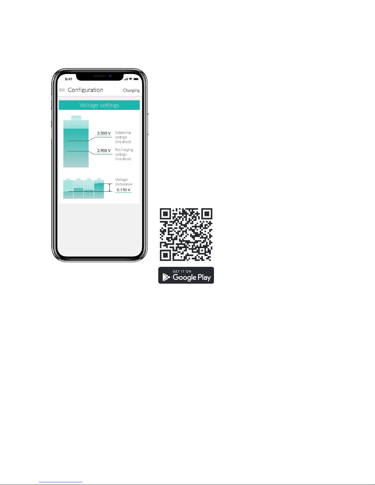
EMUS BMS mini is a freely available application for Android
and in near future iOS devices, designed specifically for monitoring the battery status in an electric vehicle or energy storage application. Using this application, any smartphone or
tablet can be connected to the device via Smartphone wireless connectivity eliminating the need for a dedicated display. Emus BMS mini application displays the most relevant statuses, such as battery cells voltages, state of charge,
estimated remaining distance, power consumption, provides
configuration for every parameter, performs firmware updates
etc. More detailed diagnostic information can be found in
separate menus.
Mobile application can be downloaded directly from
Google Store for Android smartphones. We are planning to
release an iOS application in the near future.
33
Page 35
10 Technical information
10.1 BMS mini
10.1.1 Mechanical specifications
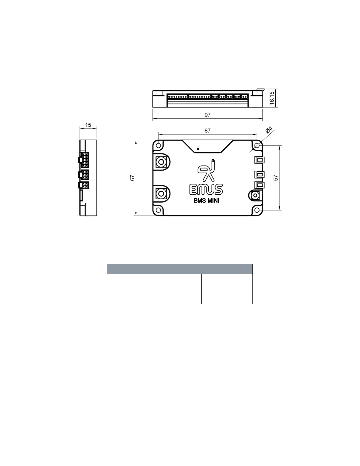
Figure 10.1: BMS mini mechanical drawing
Table 10.1: Fastening screws
Fastening screw location Screw diameter
Positive potential tabs M5
Negative potential tab M3
Mounting holes M4
34
Page 36

10.1.2 Electrical specifications
Table 10.2: BMS mini Electric Specifications
Item Value
Number of cells 6 - 16
Battery cell voltage 1.000 V ... 4.950 V
Battery pack voltage 12.0 V ... 67.2 V
Operating temperature -40°C ... +80°C
Supply power (active) 50 mW
Supply power (sleep) 0.5 mW
Balancing current 200 mA
Maximum inner contactor current 75 A
10.1.3 Other specifications
Table 10.3: BMS mini Physical Specifications
Item Value
Dimensions 97 × 67 × 15 mm
Weight 125 g
35
 Loading...