

Page 1

Controller User Manual
version 2
Original Instrucons
Page 2

Table of Contents
Section 1 - Introduction ...................................................1-1
1.1 Intended Use ......................................................................................................1-1
1.2 Release Details ..................................................................................................1-1
1.3 Warranty .............................................................................................................1-1
1.4 Returned Goods Policy .......................................................................................1-1
1.5 Movement or Resale of Mold-Masters Products or Systems .............................1-1
1.6 Copyright ............................................................................................................1-2
1.7 Units of Measure and Conversion Factors .........................................................1-2
1.8 Trademarks and Patents ....................................................................................1-3
Section 2 - Global Support ..............................................2-1
2.1 Manufacturing Facilities ......................................................................................2-1
2.2 Regional Oces .................................................................................................2-1
2.3 International Representatives .............................................................................2-2
Section 3 - Safety..............................................................3-1
i
3.1 Introduction .........................................................................................................3-1
3.2 Safety Hazards ...................................................................................................3-2
3.3 Operational Hazards ...........................................................................................3-5
3.4 General Safety Symbols .....................................................................................3-7
3.5 Wiring Check ......................................................................................................3-8
3.6 Lockout Safety ....................................................................................................3-9
3.6.1 Electrical Lockout .....................................................................................3-10
3.6.2 Energy Forms and Lockout Guidelines....................................................3-11
3.7 Grounded Earth Connections ...........................................................................3-12
3.8 Disposal ............................................................................................................3-12
3.9 E-Multi Controller Safety Hazards ....................................................................3-13
3.9.1 Operational Environment .........................................................................3-13
3.9.2 Cabinet Push / Tip Forces .......................................................................3-13
3.10 E-Multi Injection Unit Safety Labels ................................................................3-15
3.11 E-Multi Injection Unit Safety Hazards .............................................................3-16
3.12 E-Multi Injection Unit Safety Symbols .............................................................3-18
3.13 E-Multi Injection Unit Safety Guards ...............................................................3-19
3.14 E-Multi Weight Specications .........................................................................3-20
3.15 Unpack the E-Multi Controller .........................................................................3-21
3.16 Lift the E-Multi Controller ................................................................................3-23
3.16.1 Preparation ............................................................................................3-23
3.17 Lift the E-Multi Injection Unit ...........................................................................3-25
3.17.1 Prior to Lifting the E-Multi Injection Unit.................................................3-25
3.18 EM1 / EM2 / EM3 Lift Connections .................................................................3-26
3.18.1 EM1 / EM2 / EM3 Vertical Lift Connections ...........................................3-26
3.18.2 EM1 / EM2 / EM3 Horizontal Lift Connections.......................................3-27
3.19 E-Multi Injection Unit Stand Safety .................................................................3-28
© 2020 Mold-Masters (2007) Limited. All Rights Reserved.
E-Multi Controller User Manual
Page 3

Section 4 - Overview ........................................................4-1
4.1 Controller Front ...................................................................................................4-1
4.2 Controller Back - Connections Side ....................................................................4-2
4.3 Cable Holders .....................................................................................................4-3
Section 5 - Installation .....................................................5-1
5.1 Introduction .........................................................................................................5-1
5.2 Connect the Controller to the E-Multi .................................................................5-2
5.3 Connect a Robot to the Controller ......................................................................5-2
5.4 Connect the Controller to the Molding Machine .................................................5-3
5.5 Connect a Handheld HMI (Optional) ..................................................................5-4
5.6 Connect Diagnostic Computer (Optional) ...........................................................5-4
Section 6 - Operation .......................................................6-1
6.1 Introduction .........................................................................................................6-1
6.2 Isolate the Controller ..........................................................................................6-1
6.3 Switch On ...........................................................................................................6-2
6.4 Switch O (Shutdown) ........................................................................................6-2
6.4.1 Shutdown the Heating ...............................................................................6-2
6.4.2 Shutdown the Controller ............................................................................6-2
ii
Section 7 - E-Multi Controller HMI Interface ...................7-1
7.1 Introduction .........................................................................................................7-1
7.2 Cabinet Mounted Control Buttons ......................................................................7-2
7.3 E-Multi Touchscreen Interface ............................................................................7-3
7.3.1 Top Bar - Status Display ............................................................................7-4
7.3.2 Active Movement Icons ..............................................................................7-5
7.3.3 Status Icons ...............................................................................................7-5
7.3.4 Bottom Bar - Screen Navigation Buttons ...................................................7-6
7.3.5 Print Functionality ......................................................................................7-7
7.4 Screen Descriptions ...........................................................................................7-8
7.5 Overview Screen ................................................................................................7-9
7.6 Injection Settings Screen ..................................................................................7-13
7.7 Hold Settings Screen ........................................................................................7-16
7.8 Recovery Settings Screen ................................................................................7-18
7.9 Barrel Temperature Settings - Legacy Controllers* ..........................................7-21
7.10 Barrel Temperature Settings - Mold-Masters Screen .....................................7-23
7.11 Integrated Hot Runner Temperature Control (Option) .....................................7-26
7.11.1 Monitor Screen ....................................................................................... 7-27
7.11.2 Setup Screen (Supervisor Level) ........................................................... 7-31
7.11.3 Utilities Screen (Supervisor Level) ......................................................... 7-35
7.12 Integrated E-Drive Control (Option) ................................................................7-37
7.12.1 E-Drive Control Buttons .........................................................................7-38
7.13 Overview Screen ............................................................................................7-39
7.13.1 Homing ..................................................................................................7-40
7.14 Settings Screen (Supervisor Level) ................................................................7-41
7.15 Valve Gate Settings Screen ............................................................................ 7-43
7.16 Shuto-Nozzle Settings Screen ......................................................................7-45
7.17 7.17 Shuto-Nozzle Settings Screen—Kortec ................................................7-48
E-Multi Controller User Manual
© 2020 Mold-Masters (2007) Limited. All Rights Reserved.
Page 4

7.18 Production Graph Screen ...............................................................................7-51
7.18.1 Lower Menu Buttons ..............................................................................7-53
7.19 Software Oscilloscope ....................................................................................7-54
7.19.1 Measure Parameter ...............................................................................7-54
7.19.2 Trigger ....................................................................................................7-55
7.19.3 Parameter ..............................................................................................7-55
7.19.4 Line Color ..............................................................................................7-56
7.20 Process Data (PD) Protocol Screen ...............................................................7-57
7.20.1 Lower Menu Buttons ..............................................................................7-58
7.21 Main Settings Screen .....................................................................................7-59
7.22 System Settings Screen .................................................................................7-61
7.22.1 Lower Menu Buttons ..............................................................................7-63
7.23 E-Multi Radial / Servo Carriage Screen ..........................................................7-64
7.24 Auto Purge Screen .........................................................................................7-66
7.25 Info-Log Screen ..............................................................................................7-68
7.26 Programmable I/O ..........................................................................................7-70
7.26.1 I/O Monitor Screen .................................................................................7-72
7.27 Production Settings Screen ............................................................................7-73
7.28 Drive Monitor Screen ......................................................................................7-74
7.29 Task Monitor Screen .......................................................................................7-76
7.30 Drive Parameter Monitor Screen ....................................................................7-77
7.31 PID Settings ....................................................................................................7-78
7.32 Reference Settings Screen .............................................................................7-79
7.32.1 Reference Settings Screen - continued .................................................7-80
7.33 Machine Data Screen .....................................................................................7-81
7.34 Variable Monitor Screen .................................................................................7-82
7.35 Delay Settings Screen ....................................................................................7-84
7.36 Calibration Settings Screens ..........................................................................7-85
7.37 Alarms Screen ................................................................................................7-86
7.38 Mold Data Screen ...........................................................................................7-88
7.38.1 Lower Menu Buttons ..............................................................................7-89
7.39 Euromap E67 Screen .....................................................................................7-90
7.40 Legacy E67 Screen ........................................................................................7-91
iii
Section 8 - Maintenance...................................................8-1
8.1 Clean the HMI Screen ........................................................................................8-1
8.2 Preventative Maintenance ..................................................................................8-1
8.3 Verify Injection Pressure Oil Circuit
(Preload Pressure) ..............................................................................................8-2
8.3.1 Check the Preload Oil Pressure ................................................................8-2
8.4 Nozzle Protrusion Adjustment - Automatic Adjustment ....................................... 8-3
8.4.1 Carriage Home Position Calibration ..........................................................8-3
8.4.2 Manual Calibration .....................................................................................8-3
8.4.3 Automatic Calibration ................................................................................. 8-4
8.5 Injection Axis Referencing ..................................................................................8-5
8.6 Service and Repair The Controller .....................................................................8-6
8.6.1 Replacement Parts ....................................................................................8-6
8.6.2 Cleaning and Inspection ............................................................................8-6
8.7 Update Software .................................................................................................8-7
8.7.1 Save Mold Data .........................................................................................8-7
8.7.2 Save Machine Data ...................................................................................8-8
8.7.3 Install New Software ..................................................................................8-9
© 2020 Mold-Masters (2007) Limited. All Rights Reserved.
E-Multi Controller User Manual
Page 5

Section 9 - Troubleshooting ............................................9-1
9.1 Thermocouple Electrical Check ..........................................................................9-1
9.2 Heater Continuity Check .....................................................................................9-1
9.3 Transducer Output Check ...................................................................................9-1
9.4 Vibrator Valve Check ..........................................................................................9-1
9.5 Servo Motor Temperature Check ........................................................................9-2
9.6 Troubleshoot the Control System .......................................................................9-2
9.6.1 Fault and Warning Messages ....................................................................9-3
Index ......................................................................................I
Section 10 - Index .................................................................I
iv
E-Multi Controller User Manual
© 2020 Mold-Masters (2007) Limited. All Rights Reserved.
Page 6

List of Tables
Table 1-1 Release Details .........................................................................................1-1
Table 1-2 Units of Measure and Conversion Factors ...............................................1-2
Table 3-1 Safety Hazards .........................................................................................3-3
Table 3-2 Typical Safety Symbols ............................................................................. 3-7
Table 3-3 Energy Forms, Energy Sources and General
Lockout Guidelines ...........................................................................................3-11
Table 3-4 Cabinet Push / Tip Forces ......................................................................3-13
Table 3-5 E-Multi Injection Unit Safety Hazard Details ...........................................3-16
Table 3-6 Safety Symbols Used on the E-Multi Injection Unit ................................3-18
Table 3-7 E-Multi Injection Unit Shipping Dimensions and
Weight ...............................................................................................................3-20
Table 3-8 E-Multi Injection Unit Lifting Kits .............................................................3-25
Table 3-9 EM1 / EM2 / EM3 Vertical Lift Connections ............................................3-26
Table 3-10 EM1 / EM2 / EM3 Horizontal Lift Connections ......................................3-27
Table 7-1 Control Buttons .........................................................................................7-2
Table 7-2 Top Bar - Status Display ...........................................................................7-4
Table 7-3 Active Movement Icons .............................................................................7-5
Table 7-4 Status Icons ..............................................................................................7-5
Table 7-5 Screen Navigation Buttons .......................................................................7-6
Table 7-6 Printer Settings .........................................................................................7-7
Table 7-7 Overview Screen Components ...............................................................7-10
Table 7-8 Overview Screen Context Menu Buttons ................................................7-12
Table 7-9 Injection Settings Screen Components ...................................................7-13
Table 7-10 Injection Settings Screen Context Menu Buttons .................................7-15
Table 7-11 Hold Setting Screen Components ......................................................... 7-16
Table 7-12 Hold Settings Screen Context Menu Buttons .......................................7-17
Table 7-13 Recovery Settings Screen Components ...............................................7-18
Table 7-14 Recovery Settings Screen Context Menu Buttons ................................7-20
Table 7-15 Legacy Style Barrel Temperature Setting Screen
Components .....................................................................................................7-21
Table 7-16 Legacy Style Barrel Temperature Setting Screen
Context Menu Buttons ......................................................................................7-22
Table 7-17 Mold-Masters Barrel Temperature Screen
Components .....................................................................................................7-24
Table 7-18 Mold-Masters Temperature Settings Screen
Context Menu Buttons ......................................................................................7-25
Table 7-19 Monitor Screen Control Buttons ............................................................7-27
Table 7-20 Heat Zone Display ................................................................................7-28
Table 7-21 Utility Screen Elements .........................................................................7-36
Table 7-22 E-Drive Control Buttons ........................................................................7-38
Table 7-23 E-Drive Overview Screen Elements .....................................................7-39
Table 7-24 E-Drive Screen Context Menu Buttons .................................................7-40
Table 7-25 E-Drive Settings Screen Elements .......................................................7-42
Table 7-26 Valve Gate Settings Screen Elements .................................................. 7-44
Table 7-27 Production Graph Screen Elements .....................................................7-46
Table 7-28 Production Graph Screen Context Menu Buttons .................................7-46
Table 7-29 Production Graph Screen Lower Menu Buttons ...................................7-47
Table 7-30 Measure Parameter Tab Fields .............................................................7-48
Table 7-31 Process Data Screen Components ......................................................7-51
v
© 2020 Mold-Masters (2007) Limited. All Rights Reserved.
E-Multi Controller User Manual
Page 7

List of Tables
Table 7-32 Process Data Screen Lower Menu Buttons ..........................................7-52
Table 7-33 Process Data Screen Context Menu Buttons .......................................7-52
Table 7-34 Systems Settings Screen Components ................................................7-55
Table 7-35 System Settings Screen Lower Menu Buttons .....................................7-57
Table 7-36 E-Multi Radial / Servo Carriage Screen Components ..........................7-58
Table 7-37 E-Multi Radial / Servo Carriage Screen Context
Menu Buttons ....................................................................................................7-59
Table 7-38 Auto Purge Screen Elements ................................................................7-61
Table 7-39 Info-Log Screen Elements ....................................................................7-62
Table 7-40 Info-Log Menu Buttons .........................................................................7-63
Table 7-41 Info-Log Filter Elements ........................................................................7-63
Table 7-42 Programmable I/O Screen Components ...............................................7-64
Table 7-43 I/O Monitor Screen Components ..........................................................7-66
Table 7-44 Production Settings Screen Components .............................................7-67
Table 7-45 Drive Manager Screen Components ....................................................7-68
Table 7-46 Drive Parameter Monitor Screen Components .....................................7-71
Table 7-47 PID Settings Screen Components ........................................................7-72
Table 7-48 Reference Settings Screen Elements ...................................................7-73
Table 7-49 Reference Settings Screen Context Menu Buttons ..............................7-74
Table 7-50 Machine Data Screen Components ......................................................7-75
Table 7-51 Variable Monitor Screen Components ..................................................7-77
Table 7-52 Delay Setting Screen Components .......................................................7-78
Table 7-53 Calibration Settings Screen Components .............................................7-79
Table 7-54 Alarms Screen Components .................................................................7-81
Table 7-55 Mold Data Screen Components ............................................................7-82
Table 7-56 Mold Data Screen Menu Buttons ..........................................................7-83
Table 7-57 Euromap E67 Screen Components ......................................................7-84
Table 8-1 Preventive Maintenance Schedule ...........................................................8-1
Table 9-1 Fault and Warning Messages ...................................................................9-3
Table 9-2 Integrated HRC Warning Messages .........................................................9-4
vi
E-Multi Controller User Manual
© 2020 Mold-Masters (2007) Limited. All Rights Reserved.
Page 8

List of Figures
Figure 3-1 Injection molding machine hazard areas .................................................3-2
Figure 3-2 E-Multi controller safety hazards ...........................................................3-14
Figure 3-3 E-Multi injection unit safety labels .........................................................3-15
Figure 3-4 Guards layout ........................................................................................3-19
Figure 3-5 Correct side of crate to open .................................................................3-21
Figure 3-6 Remove top row of screws ....................................................................3-21
Figure 3-7 Remove cross brace screws .................................................................3-22
Figure 3-8 Remove screws from side and bottom ..................................................3-22
Figure 3-9 Eyebolts and washers ...........................................................................3-23
Figure 3-10 Install eyebolts and washers ...............................................................3-24
Figure 3-11 Attach slings to all four eyebolts ..........................................................3-24
Figure 3-12 Do not use the motor as a lifting point .................................................3-25
Figure 4-1 Controller front ........................................................................................4-1
Figure 4-2 Controller back connections ....................................................................4-2
Figure 4-3 Diagnostic kit (option) ..............................................................................4-2
Figure 4-4 Cable holders ..........................................................................................4-3
Figure 4-5 Attach cable holders ................................................................................4-3
Figure 5-1 EM3 servo cable routing .........................................................................5-2
Figure 5-2 Robot jumper plug ...................................................................................5-2
Figure 5-3 E-Multi connection locations ...................................................................5-3
Figure 5-4 Handheld HMI and connection ................................................................5-4
Figure 5-5 Wireless network icon .............................................................................5-5
Figure 6-1 E-Multi main power switch ......................................................................6-1
Figure 6-2 Button strip below controller display (HMI) ..............................................6-2
Figure 7-1 Cabinet mounted control buttons ............................................................7-2
Figure 7-2 Print functionality screen .........................................................................7-7
Figure 7-3 Overview screen .....................................................................................7-9
Figure 7-4 Injection settings screen ........................................................................7-13
Figure 7-5 Hold settings screen ..............................................................................7-16
Figure 7-6 Recovery settings screen ......................................................................7-18
Figure 7-7 Legacy style barrel temperature settings screen ..................................7-21
Figure 7-8 Mold-Masters barrel temperature settings
screen ...............................................................................................................7-23
Figure 7-9 Integrated hot runner controller overview
screen ...............................................................................................................7-26
Figure 7-10 Hot runner controller monitor screen ...................................................7-27
Figure 7-11 Setup screen (supervisor level) ........................................................... 7-31
Figure 7-12 Utilities screen (supervisor level) ........................................................7-35
Figure 7-13 E-Drive control screen components ....................................................7-37
Figure 7-14 E-Drive controller overview screen .....................................................7-39
Figure 7-15 E-Drive setting screen .........................................................................7-41
Figure 7-16 Valve gate settings screen ..................................................................7-43
Figure 7-17 Production graph screen ....................................................................7-45
Figure 7-18 Production graph screen lower menu buttons .....................................7-47
Figure 7-19 Process data protocol screen ..............................................................7-51
Figure 7-20 Process data screen lower menu buttons ...........................................7-52
Figure 7-21 Main setting screen .............................................................................7-53
Figure 7-22 Machine specication screen icons .....................................................7-54
Figure 7-23 System settings screen .......................................................................7-55
vii
© 2020 Mold-Masters (2007) Limited. All Rights Reserved.
E-Multi Controller User Manual
Page 9

List of Figures
Figure 7-24 System settings screen lower menu buttons .......................................7-57
Figure 7-25 E-Multi Radial / Servo carriage screen ................................................7-58
Figure 7-26 Auto purge screen ...............................................................................7-60
Figure 7-27 Info-log screen ....................................................................................7-62
Figure 7-28 Programmable I/O screen ...................................................................7-64
Figure 7-29 I/O monitor screen ...............................................................................7-66
Figure 7-30 Production settings screen ..................................................................7-67
Figure 7-31 Drive monitor screen ...........................................................................7-68
Figure 7-32 Task monitor screen ............................................................................7-70
Figure 7-33 Drive parameter monitor screen ..........................................................7-71
Figure 7-34 Reference settings screen ..................................................................7-73
Figure 7-35 Machine data screen ...........................................................................7-75
Figure 7-36 Variable monitor screen ......................................................................7-76
Figure 7-37 Delay settings screen ..........................................................................7-78
Figure 7-38 Calibration settings screen ..................................................................7-79
Figure 7-39 Alarms screen .....................................................................................7-80
Figure 7-40 Mold data screen .................................................................................7-82
Figure 7-41 Mold data screen lower menu buttons ................................................7-83
Figure 7-42 Euromap E67 screen ..........................................................................7-84
Figure 8-1 Nozzle protrusion adjustment - Radial and
Servo carriage models ........................................................................................8-4
Figure 9-1 Alarms screen with motor temperature alarm .........................................9-2
viii
E-Multi Controller User Manual
© 2020 Mold-Masters (2007) Limited. All Rights Reserved.
Page 10
INTRODUCTION
Section 1 - Introduction
The purpose of this manual is to assist users in the integration, operation
and maintenance of the E-Multi controller. This manual is designed to cover
most system congurations. If you need additional information specic to your
system please contact your representative or a Mold-Masters oce whose
location can be found in the “Global Support” section.
1.1 Intended Use
The E-Multi controller is an electrical switching device designed for use with
the E-Multi Auxiliary Injection Unit (AIU). It is designed to be safe during
normal operation. Any other uses would fall outside the engineered intent
of this machine which may be a safety hazard and would void any and all
warranties.
This manual is written for use by skilled persons who are familiar with
injection molding machinery and their terminology. Operators should be
familiar with plastic injection molding machines and the controls of such
equipment. Maintenance persons should have sucient understanding of
electrical safety to appreciate the dangers of 3-phase supplies. They should
know how to take appropriate measures to avoid any danger from electrical
supplies.
1-1
1.2 Release Details
Table 1-1 Release Details
Document Number Release Date Version
AIU-UM-EN-01-02-11 May 2019 02-11
AIU-UM-EN-01-03 August 2020 03
1.3 Warranty
For current warranty information please refer to the documents available from
our website: https://www.milacron.com/mold-masters-warranty/ or contact
your Mold-Masters representative.
1.4 Returned Goods Policy
Please do not return any parts to Mold-Masters without pre-authorization and
a return authorization number supplied by Mold-Masters.
Our policy is one of continuous improvement and we reserve the right to alter
product specications at any time without giving notice.
1.5 Movement or Resale of Mold-Masters
Products or Systems
This documentation is intended for use in the country of destination for which
the product or system was purchased.
Mold-Masters takes no responsibility for documentation of products or
systems if they are relocated or resold outside the intended country of
destination, as stated on the accompanying invoice and/or waybill.
© 2020 Mold-Masters (2007) Limited. All Rights Reserved.
E-Multi Controller User Manual
Page 11
INTRODUCTION
1.6 Copyright
© 2020 Mold-Masters (2007) Limited. All Rights Reserved. Mold-Masters
and the Mold-Masters logo are trademarks of Mold-Masters.
1.7 Units of Measure and Conversion Factors
NOTE
The dimensions given in this manual are from original manufacturing
drawings.
All values in this manual are in S.I. units or subdivisions of these units.
Imperial units are given in parenthesis immediately after the S.I. units.
Table 1-2 Units of Measure and Conversion Factors
Abbreviation Unit Conversion Value
bar Bar 14.5 psi
in. Inch 25.4 mm
kg Kilogram 2.205 lb
kPa Kilopascal 0.145 psi
gal Gallon 3.785 l
lb Pound 0.4536 kg
lbf Pound force 4.448 N
lbf.in. Pound force inch 0.113 Nm
l Litre 0.264 gallon
min Minute
mm Millimeter 0.03937 in.
mΩ Milli Ohm
N Newton 0.2248 lbf
Nm Newton Meter 8.851 lbf.in.
psi Pound per square inch 0.069 bar
psi Pound per square inch 6.895 kPa
rpm Revolutions per minute
s Second
°
°
C
°
F
Degree
Degree Celsius
Degree Fahrenheit
0.556 (°F -32)
1.8 °C +32
1-2
®
E-Multi Controller User Manual
© 2020 Mold-Masters (2007) Limited. All Rights Reserved.
Page 12

INTRODUCTION
1.8 Trademarks and Patents
ACCU-VALVE, DURA, E-MULTI, FLEX-DURA FLEX-SERIES, FUSION-SERIES, HOT
EDGE, MASTERPROBE, MASTER-SHOT, MOLD-MASTERS, MELT-DISK, MOLD-
MASTERS ACADEMY, MASTER-SERIES, MASTERSOLUTION, MASTERSPEED, MERLIN,
MOLD-MASTERS SYSTEM, MPET, STACK-LINK, are the registered trademarks of MOLD-
MASTERS (2007) LIMITED.
Information contained herein is, to our best knowledge, true and accurate, but all
recommendations or suggestions are made without guarantee. Since the conditions of
use are beyond our control, Mold-Masters disclaims any liability incurred in connection
with the use of our products and information contained herein. No person is authorized to
make any statement or recommendation not contained herein, and any such statement or
recommendation so made shall not bind Mold-Masters. Furthermore, nothing contained herein
shall be construed as a recommendation to use any product in conict with existing patents
covering any products or its use, and no license implied or in fact granted herein under the
claims of any patents.
No part of this publication may be reproduced or transmitted in any form or by any means,
electronic or mechanical, including photocopy, recording, or any information storage and
retrieval system without permission in writing from the publisher. All details, standards
and specications may be altered in accordance with technical development without prior
notication.
1-3
May be manufactured under one or more of the following U.S. Patents:
5792493, 5795599, 5820899, 5843361, 5849343, 5853777, 5935615, 5935616, 5935621, 5942257,
5952016, 5980236, 6009616, 6017209, 6030198, 6030202, 6062841, 6074191, 6077067, 6079972,
6095790, 6099780, 6113381, 6135751, 6162043, 6162044, 6176700, 6196826, 6203310, 6230384,
6270711, 6274075, 6286751, 6302680, 6318990, 6323465, 6348171, 6350401, 6394784, 6398537,
6405785, 6440350, 6454558, 6447283, 6488881, 6561789, 6575731, 6625873, 6638053, 6648622,
6655945, 6675055, 6688875, 6701997, 6739863, 6752618, 6755641, 6761557, 6769901, 6776600,
6780003, 6789745, 6830447, 6835060, 6840758, 6852265, 6860732, 6869276, 6884061, 6887418,
6890473, 6893249, 6921257, 6921259, 6936199, 6945767, 6945768, 6955534, 6962492, 6971869,
6988883, 6992269, 7014455, 7018197, 7022278, 7025585, 7025586, 7029269, 7040378, 7044191,
7044728, 7048532, 7086852, 7105123, 7108502, 7108503, 7115226, 7118703, 7118704, 7122145,
7125242, 7125243, 7128566, 7131832, 7131833, 7131834, 7134868, 7137806, 7137807, 7143496,
7156648, 7160100, 7160101, 7165965, 7168941, 7168943, 7172409, 7172411, 7175419, 7175420,
7179081, 7182591, 7182893, 7189071, 7192268, 7192270, 7198740, 7201335, 7210917, 7223092,
7238019, 7244118, 7252498, 7255555, 7258536, 7270538, 7303720, 7306454, 7306455, 7314367,
7320588, 7320589, 7320590 7326049, 7344372, 7347684, 7364425, 7364426, 7370417,7377768,
7381050, 7396226, 7407379, 7407380, 7410353, 7410354, 7413432, 7416402, 7438551,
7462030, 7462031, 7462314, 7465165, 7470122, 7507081, 7510392, 7513771, 7513772, 7517214,
7524183, 7527490, 7544056, 7547208, 7553150, 7559760, 7559762, 7565221, 7581944, 7611349,
7614869, 7614872, 7618253, 7658605, 7658606, 7671304, 7678320, 7686603, 7703188, 7713046,
7722351, 7731489, 7753676, 7766646, 7766647, 7775788, 7780433, 7780434, 7794228, 7802983,
7803306, 7806681, 7824163, 7845936, 7850442, 7874833, 7877163, 7891969, 7918660, 7918663,
7931455, 7963762, 7988445, 7998390, 8062025, 8066506, 8113812, 8142182, 8152513, 8167608,
8202082, 8206145, 8210842, 8241032, 8280544, 8282386, 8308475, 8308476, 8328546, 8353697,
8414285, 8425216, 8449287, 8465688, 8469687, 8475155, 8475158, 8480391, 8568133, 8690563,
8715547,8753102, 8757998, 8758002, 8845321, 8899964, 8940202, 8985997, 9004906, 9028243,
9073246, 9186830, 9186833, 9227351,9248593, 9272455, 9327436, D525592, RE38265, RE38396,
RE38920, RE39935, RE40478, RE40952, RE41536E, RE41648E+ Pending.
© 2019 MOLD-MASTERS (2007) LIMITED, ALL RIGHTS RESERVED
© 2020 Mold-Masters (2007) Limited. All Rights Reserved.
E-Multi Controller User Manual
Page 13

Mold-Masters Regional Offices
GLOBAL SUPPORT
Section 2 - Global Support
2.1 Manufacturing Facilities
2-1
GLOBAL HEADQUARTERS
CANADA
Mold-Masters (2007) Limited
233 Armstrong Avenue
Georgetown, Ontario
Canada L7G 4X5
tel: +1 905 877 0185
fax: +1 905 877 6979
SOUTH AMERICAN
HEADQUARTERS
BRAZIL
Mold-Masters do Brasil Ltda.
R. James Clerk Maxwel,
280 – Techno Park, Campinas
São Paulo, Brazil, 13069-380
tel: +55 19 3518 4040
UNITED KINGDOM & IRELAND
Mold-Masters (UK) Ltd
Netherwood Road
Rotherwas Ind. Est.
Hereford, HR2 6JU
United Kingdom
tel: +44 1432 265768
fax: +44 1432 263782
EUROPEAN HEADQUARTERS
GERMANY / SWITZERLAND
Mold-Masters Europa GmbH
Neumattring 1
76532 Baden-Baden, Germany tel:
+49 7221 50990
fax: +49 7221 53093
INDIA
Mold-Masters Technologies Private
Limited
# 247, Alagesan Road,
Shiv Building, Saibaba Colony.
Coimbatore T. N.
India 641 011
tel: +91 422 423 4888
fax: +91 422 423 4800
USA
Mold-Masters Injectioneering LLC
29111 Stephenson Highway
Madison Heights, MI 48071, USA
tel: +1 800 450 2270 (USA only)
tel: +1 (248) 544-5710
fax: +1 (248) 544-5712
ASIAN HEADQUARTERS
CHINA/HONG KONG/TAIWAN
Mold-Masters (KunShan) Co, Ltd
Zhao Tian Rd
Lu Jia Town, KunShan City
Jiang Su Province
People’s Republic of China
tel: +86 512 86162882
fax: +86 512-86162883
JAPAN
Mold-Masters K.K.
1-4-17 Kurikidai, Asaoku
Kawasaki, Kanagawa
Japan, 215-0032
tel: +81 44 986 2101
fax: +81 44 986 3145
2.2 Regional Ofces
AUSTRIA / East and South
East Europe
Mold-Masters Handelsges.m.b.H.
Pyhrnstrasse 16
A-4553 Schlierbach
Austria
tel: +43 7582 51877
fax: +43 7582 51877 18
ITALY
Mold-Masters Italia
Via Germania, 23
35010 Vigonza (PD)
Italy
tel: +39 049/5019955
fax: +39 049/5019951
© 2020 Mold-Masters (2007) Limited. All Rights Reserved.
CZECH REPUBLIC
Mold-Masters Europa GmbH
Hlavni 823
75654 Zubri
Czech Republic
tel: +420 571 619 017
fax: +420 571 619 018
KOREA
Mold-Masters Korea Ltd.
E dong, 2nd floor, 2625-6,
Jeongwang-dong, Siheung
City, Gyeonggi-do, 15117,
South Korea
Tel: +82-31-431-4756
[email protected]
FRANCE
Mold-Masters France
ZI la Marinière,
2 Rue Bernard Palissy
91070 Bondoufle, France
tel: +33 (0) 1 78 05 40 20
fax: +33 (0) 1 78 05 40 30
MEXICO
Milacron Mexico Plastics Services
S.A. de C.V.
Circuito El Marques norte #55
Parque Industrial El Marques
El Marques, Queretaro C.P. 76246
Mexico
tel: +52 442 713 5661 (sales)
tel: +52 442 713 5664 (service)
E-Multi Controller User Manual
Page 14

Mold-Masters Regional Offices (cont.)
Mold-Masters International Representatives
GLOBAL SUPPORT
Regional Ofces - continued
SINGAPORE*
Mold-Masters Singapore PTE. Ltd.
No 48 Toh Guan Road East
#06-140 Enterprise Hub
Singapore 608586
Republic of Singapore
tel: +65 6261 7793
fax: +65 6261 8378
[email protected]
*Coverage includes Southeast
Asia, Australia, and New Zealand
SPAIN
Ferromatik Milacron /
Mold Masters Europa GmbH
C/. Enric Morera, 7
Polig. Ind. Foinvasa
08110 Montcada i Reixac
Barcelona, Spain
tel: +34 93 575 41 29
fax: +34 93 575 34 19
[email protected]
2-2
TURKEY
Mold-Masters Europa GmbH
Merkezi Almanya Türkiye
İstanbul Şubesi
Alanaldı Caddesi Bahçelerarası
Sokak No: 31/1
34736 İçerenköy-Ataşehir
Istanbul, Turkey
tel: +90 216 577 32 44
fax: +90 216 577 32 45
[email protected]
2.3 International Representatives
Argentina
Sollwert S.R.L.
La Pampa 2849 2∫ B
C1428EAY Buenos Aires
Argentina
tel: +54 11 4786 5978
fax: +54 11 4786 5978 Ext.
35 [email protected]
Denmark*
Englmayer A/S
Dam Holme 14-16
DK – 3660 Stenloese
Denmark tel: +45 46 733847
fax: +45 46 733859
[email protected]
*Coverage includes Norway
and Sweden
Belarus
HP Promcomplect
Sharangovicha 13
220018 Minsk
tel: +375 29 683-48-99
fax: +375 17 397-05-65
e:[email protected]
Finland**
Oy Scalar Ltd.
Tehtaankatu
10 11120 Riihimaki
Finland
tel: +358 10 387 2955
fax: +358 10 387 2950
[email protected]
**Coverage includes Estonia
Bulgaria
Mold-Trade OOD
62, Aleksandrovska
St. Ruse City
Bulgaria
tel: +359 82 821 054
fax: +359 82 821 054
[email protected]
Greece
Ionian Chemicals S.A.
21 Pentelis Ave.
15235 Vrilissia, Athens
Greece
tel: +30 210 6836918-9
fax: +30 210 6828881
[email protected]
E-Multi Controller User Manual
© 2020 Mold-Masters (2007) Limited. All Rights Reserved.
Page 15

SAFETY
Section 3 - Safety
3.1 Introduction
Please be aware that the safety information provided by Mold-Masters
does not absolve the integrator and employer from understanding and
following international and local standards for safety of machinery. It is the
responsibility of the end integrator to integrate the nal system, provide
necessary e-stop connections, safety interlocks and guarding, to choose the
appropriate electrical cable for the region of use and to ensure compliance
with all relevant standards.
It is the responsibility of the employer to:
• Properly train and instruct its personnel in the safe operation of
equipment, including the use of all the safety devices.
• Provide its personnel with all necessary protective clothing, including such
items as a face shield and heat resistant gloves.
• Ensure the original and continuing competence of personnel caring for,
setting up, inspecting and maintaining injection molding equipment.
• Establish and follow a program of periodic and regular inspections of
injection molding equipment to ensure it is in safe operating condition and
proper adjustment.
3-1
• Ensure that no modications, repairs or rebuild of portions are made
to the equipment that reduces the level of safety existing at time of
manufacture or remanufacture.
© 2020 Mold-Masters (2007) Limited. All Rights Reserved.
E-Multi Controller User Manual
Page 16
SAFETY
3.2 Safety Hazards
WARNING
Also refer to all machine manuals and local regulations and codes for safety
information.
The following safety hazards are most commonly associated with injection
molding equipment. See European Standard EN201 or American Standard
ANSI/SPI B151.1.
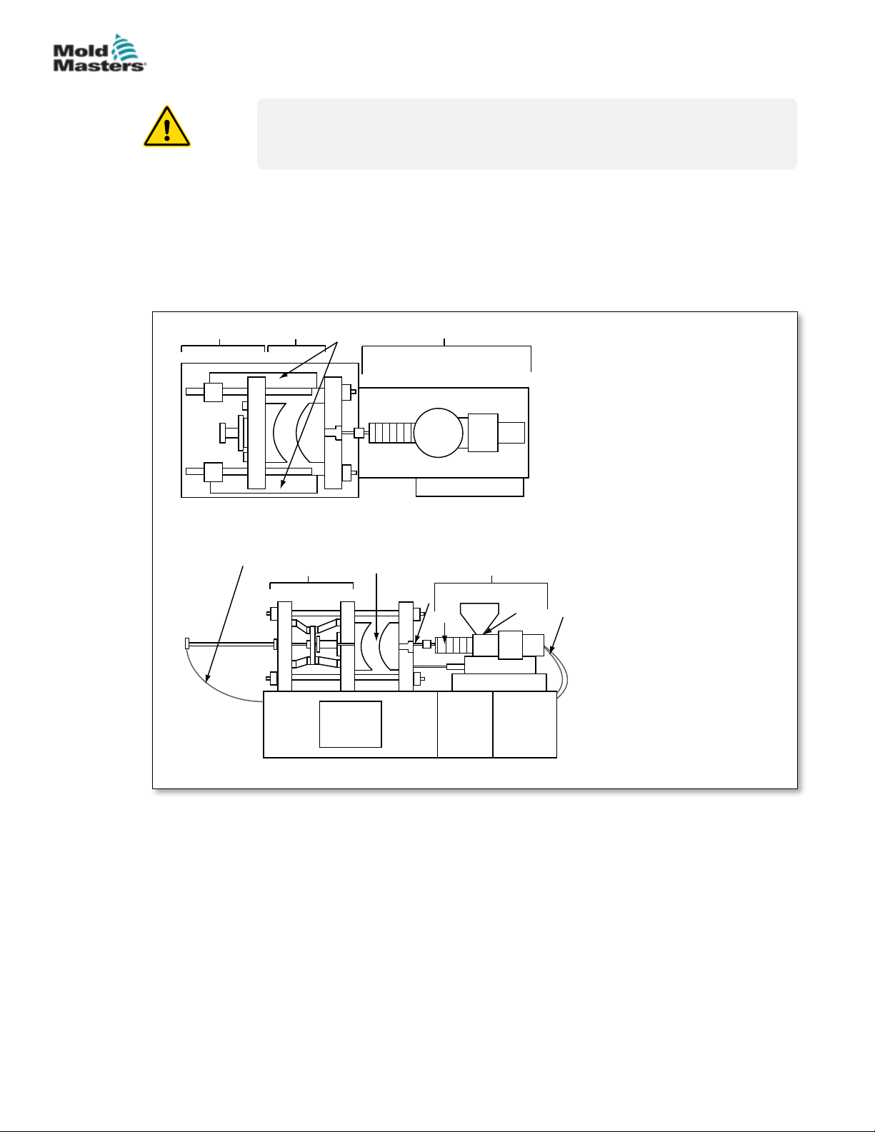
Refer to the illustration of hazard areas below when reading the Safety
Hazards Figure 3-1 on page 3-2.
3-2
2
10
3
Top view with guards removed
9
2
5
1. Mold area
2. Clamping mechanism area
3. Area of movement of
core and ejector drive
mechanisms outside areas
1 and 2
4. Machine nozzle area
5. Plasticating and / or
injection unit area
1
4
7
5
6
6. Feed opening area
7. Area of the heater bands
9
of the plasticizing and / or
injection cylinders
8. Parts discharge area
9. Hoses
8
10. Area inside the guards and
outside the mold area
Front view with guards removed
Figure 3-1 Injection molding machine hazard areas
E-Multi Controller User Manual
© 2020 Mold-Masters (2007) Limited. All Rights Reserved.
Page 17
SAFETY
Safety Hazards - continued
Table 3-1 Safety Hazards
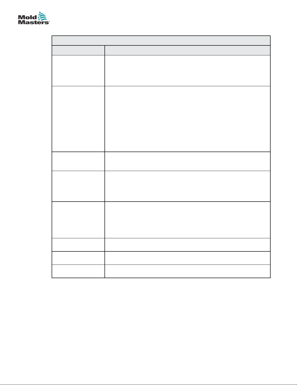
Hazard Area Potential Hazards
3-3
Mold Area
Area between the
platens.
See Figure 3-1 area 1
Clamping
Mechanism Area
See Figure 3-12 area
2
Movement of
Drive Mechanisms
Outside the Mold
Area and Outside
the Clamping
Mechanism Area
See Figure 3-1 area 3
Nozzle Area
The nozzle area is
the area between the
barrel and the sprue
bushing.
See Figure 3-1 area 4
Mechanical Hazards
Crushing and / or shearing and / or impact hazards caused by:
• Movement of the platen.
• Movements of the injection barrel(s) into the mold area.
• Movements of cores and ejectors and their drive mechanisms.
• Tie bar motion.
Thermal Hazards
Burns and / or scalds due to operating temperature of:
• The mold heating elements.
• Material released from/through the mold.
Mechanical Hazards
Crushing and / or shearing and / or impact hazards caused by:
• Movement of the platen.
• Movement of the drive mechanism of the platen.
• Movement of the core and ejector drive mechanism.
Mechanical Hazards
Mechanical hazards of crushing, shearing and / or impact caused by the
movements of:
• Core and ejector drive mechanisms.
Mechanical Hazards
Crushing, shearing hazards and / or impact hazards caused by:
• Forward movement of the plasticizing and / or injection unit including
nozzle.
• Movements of parts of the power-operated nozzle shuto and their
drives.
• Over pressurization in the nozzle.
Thermal Hazards
Burns and or scalds due to operating temperature of:
• The nozzle.
• Material discharging from the nozzle.
Plasticizing and / or
Injection Unit Area
Area from the adapter
/ barrel head / end cap
to the extruder motor
above the sled
including the carriage
cylinders.
See Figure 3-1 area 5
Feed Opening
See Figure 3-1 area 6
© 2020 Mold-Masters (2007) Limited. All Rights Reserved.
Mechanical Hazards
Crushing, shearing and / or drawn-into hazards caused by:
• Unintentional gravity movements e.g. for machines with plasticizing
• The movements of the screw and / or the injection plunger in the
• Movement of the carriage unit.
Thermal Hazards
Burns and / or scalds due to operating temperature of:
• The plasticizing and / or injection unit.
• The heating elements e.g. heater bands.
• The material and / or vapors discharging from the vent opening, feed
Mechanical and / or Thermal Hazard
• Hazards due to reduction in mechanical strength of the plasticizing and
Pinching and crushing between injection screw movement and housing.
and / or injection unit positioned above the mold area.
cylinder accessible through the feed opening.
throat or hopper.
/ or injection cylinder due to overheating.
E-Multi Controller User Manual
Page 18
SAFETY
Safety Hazards - continued
Table 3-1 Safety Hazards
Hazard Area Potential Hazards
3-4
Area of the Heater
Bands of the
Plasticizing and / or
Injection Cylinders
See Figure 3-1 area 7
Parts Discharge Area
See Figure 3-1 area 8
Hoses
See Figure 3-1 area 9
Area Inside the
Guards and Outside
the Mold Area
See Figure 3-1 area
10
Electrical Hazards • Electrical or electromagnetic disturbance generated by the motor
Hydraulic
Accumulators
Power Operated
Gate
Vapors and Gases Certain processing conditions and / or resins can cause hazardous fumes
Burns and / or scalds due to operating temperature of:
• The plasticizing and / or injection unit.
• The heating elements e.g. heater bands.
• The material and / or vapors discharging from the vent opening, feed
throat or hopper.
Mechanical Hazards
Accessible Through the Discharge Area
Crushing, shearing and / or impact hazards caused by:
• Closing movement of the platen.
• Movements of cores and ejectors and their drive mechanisms.
Thermal Hazards
Accessible through the discharge area
Burns and or scalds due to operating temperature of:
• The mold.
• Heating elements of the mold.
• Material released from / through the mold.
• Whipping action caused by hose assembly failure.
• Possible release of uid under pressure that can cause injury.
• Thermal hazards associated with hot uid.
Crushing and / or shearing and / or impact hazards caused by:
• Movement of the platen.
• Movement of the drive mechanism of the platen.
• Movement of the core and ejector drive mechanism.
• Clamp opening movement.
control unit.
• Electrical or electromagnetic disturbance that can cause failures in the
machine control systems and adjacent machine controls.
• Electrical or electromagnetic disturbance generated by the motor
control unit.
High pressure discharge.
Crush or impact hazards caused by the movement of the power operated
gates.
or vapors.
E-Multi Controller User Manual
© 2020 Mold-Masters (2007) Limited. All Rights Reserved.
Page 19

SAFETY
3.3 Operational Hazards
WARNINGS
• Refer to all machine manuals and local regulations and codes for safety
information.
• The equipment supplied is subjected to high injection pressures and high
temperatures. Ensure that extreme caution is observed in the operation
and maintenance of the injection molding machines.
• Only fully trained personnel should operate or maintain equipment.
• Do not operate the equipment with unconned long hair, loose clothing
or jewelry, including name badges, neckties, etc. These may get caught
in the equipment and can cause death or serious injury.
• Never disable or bypass a safety device.
• Ensure that the protective guards are placed around the nozzle to
prevent the material from splashing or drooling.
• A burn hazard exists from material during routine purging. Wear heatresistant personal protective equipment (PPE) to prevent burns from
contact with hot surfaces or splatter of hot material and gases.
• Material purged from machine may be extremely hot. Ensure protective
guards are in place around the nozzle to prevent material from
splashing. Use proper personal protective equipment.
3-5
• All operators should wear personal protective equipment, such as face
shields and use heat resistant gloves when working around the feed
inlet, purging the machine or cleaning the gates of the mold.
• Remove purged material from the machine immediately.
• Decomposing or burning material could result in noxious gases being
emitted from the purged material, feed inlet or mold.
• Ensure proper ventilation and exhaust systems are in place to help
prevent inhalation of harmful gases and vapors.
• Consult manufacturer’s Material Safety Data Sheets (MSDS).
• Hoses tted to the mold will contain high or low temperature uids or air
under high pressure. The operator must shut down and lockout these
systems as well as relieving any pressure before performing any work
with these hoses. Regularly inspect and replace all exible hoses and
restraints.
• Water and / or hydraulics on the mold may be in close proximity to
electrical connections and equipment. Water leakage may cause an
electrical short circuit. Hydraulic uid leakage may cause a re hazard.
Always keep water and / or hydraulic hoses and ttings in good condition
to avoid leaks.
• Never perform any work on the mold machine unless the hydraulic pump
has been stopped.
• Check frequently for possible oil leaks / water leaks. Stop the machine
and make repairs.
© 2020 Mold-Masters (2007) Limited. All Rights Reserved.
E-Multi Controller User Manual
Page 20

SAFETY
Operational Hazards - continued
WARNING
• Make sure that the cables are connected to the correct motors. Cables
and motors are clearly labeled. Reversing the cables can result in
unexpected and uncontrolled motion causing a safety risk or damage to
the machine.
• A crushing hazard exists between the nozzle and mold melt inlet during
carriage forward motion.
• A possible shearing hazard exists between the edge of the injection
guard and the injection housing during injection.
• The open feed port could present a hazard to a nger or a hand
inserted during operation of the machine.
• The electric servo motors could overheat presenting a hot surface which
could cause burns to someone touching it.
• The barrel, barrel head, nozzle, heater bands and mold components are
hot surfaces which could result in burns.
• Keep ammable liquids or dust away from the hot surfaces as they
could ignite.
3-6
• Follow good housekeeping procedures and keep oors clean to prevent
slips, trips and falls due to spilled material on the work oor.
• Apply engineering controls or hearing conservation programs as
necessary to control noise.
• When doing any work on the machine that requires moving and lifting
the machine, ensure that lifting equipment (eyebolts, fork lift truck,
cranes, etc.) will have sucient capacity to handle mold, auxiliary
injection unit or Hot Runner weight.
• Connect all lifting devices and support the machine using a crane of
adequate capacity before commencing work. Failure to support the
machine can result in severe injury or death.
• Mold cable from the controller to the mold must be removed before
servicing the mold.
E-Multi Controller User Manual
© 2020 Mold-Masters (2007) Limited. All Rights Reserved.
Page 21
SAFETY
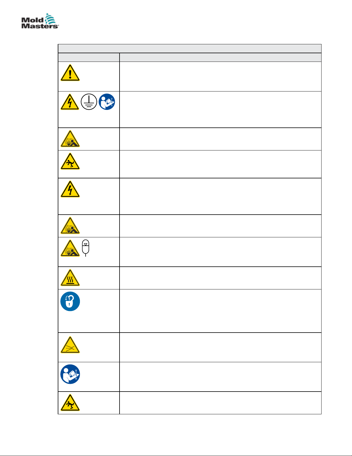
3.4 General Safety Symbols
Table 3-2 Typical Safety Symbols
Symbol General Description
General – Warning
Indicates an immediate or potentially hazardous situation, which if not
avoided, could result in a serious injury or death, and / or damage to
equipment.
Warning – Barrel Cover Grounding Strap
Lockout / tagout procedures must be followed before removing the barrel
cover. Barrel cover can become energized upon removal of grounding straps
and contact can result in death or serious injury. Grounding straps must be
reconnected before reconnecting power to machine.
Warning – Crushing and / or Impact Points
Contact with moving parts can cause serious crushing injury. Always keep
guards in place.
Warning – Crush Hazard Closing Mold
Warning – Hazardous Voltage
Contact with hazardous voltages will cause death or serious injury. Turn o
power and review electrical schematics before servicing equipment. May
contain more than one live circuit. Test all circuits before handling to make
sure circuits have been de-energized.
Warning – High Pressure
Overheated uids may cause severe burns. Discharge pressure before
disconnecting water lines.
Warning – High Pressure Accumulator
Sudden release of high pressure gas or oil can cause death or serious
injury. Discharge all gas and hydraulic pressure before disconnecting or
disassembling accumulator.
Warning – Hot Surfaces
Contact with exposed hot surfaces will cause serious burn injury. Wear
protective gloves when working near these areas.
Mandatory – Lockout / Tagout
Ensure that all energies are properly locked out, and remain locked out
until the service work is completed. Servicing equipment without disabling
all internal and external power sources can cause death or serious injury.
De-energize all internal and external power sources (electrical, hydraulic,
pneumatic, kinetic, potential, and thermal).
Warning – Molten Material Splashing Hazard
Molten material or high pressure gas can cause death or severe burns. Wear
personal protective equipment while servicing the feed throat, nozzle, mold
areas and when purging the injection unit.
Warning – Read Manual Before Operation
Personnel should read and understand all instructions in the manuals before
working on equipment. Only properly trained personnel should operate the
equipment.
Warning – Slip, Trip or Fall Hazard
Do not climb on equipment surfaces. Serious slip, trip, or fall injuries can
result from personnel climbing on equipment surfaces.
3-7
© 2020 Mold-Masters (2007) Limited. All Rights Reserved.
E-Multi Controller User Manual
Page 22
SAFETY
General Safety Symbols - continued
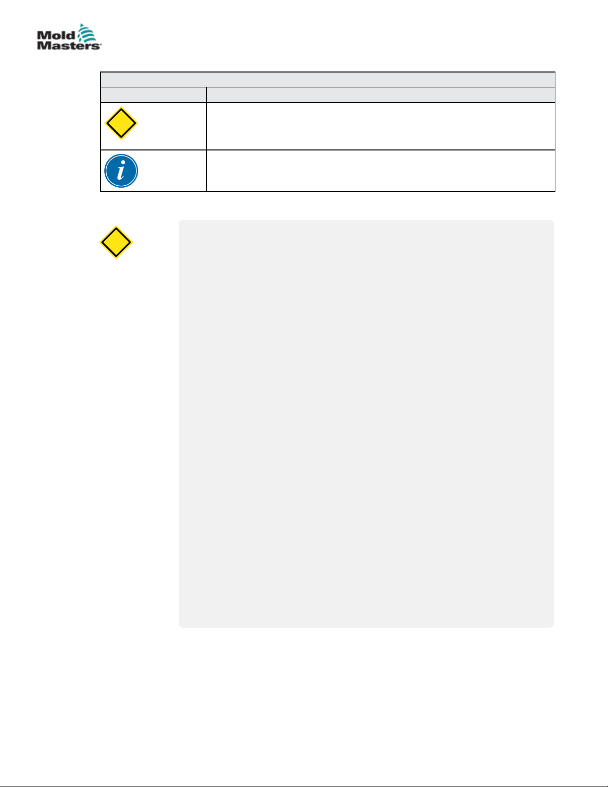
Table 3-2 Typical Safety Symbols
Symbol General Description
Caution
CAUTION
Failure to follow instructions may damage equipment.
Important
Indicates additional information or used as a reminder.
3.5 Wiring Check
CAUTION
CAUTION
System Mains Supply Wiring:
• Before connecting the system to a power supply, it is important to check
that the wiring between the system and the power supply has been
done correctly.
• Particular attention must be given to the current rating of the power
supply. For example, if a controller is rated at 63A, then the power
supply must also be rated at 63A.
3-8
• Check that the phases of power supply are wired correctly.
Controller to Mold Wiring:
• For separate power and thermocouple connections, ensure that the
power cables are never connected to the thermocouple connectors and
vice-versa.
• For mixed power and thermocouple connections, ensure that the power
and thermocouple connections have not been wired incorrectly.
Communications Interface and Control Sequence:
• It is the customer’s responsibility to verify functionality of any custom
machine interface at safe speeds, prior to operating equipment in the
production environment at full speed in automatic mode.
• It is the customer’s responsibility to verify all required motion sequences
are correct, prior to operating equipment in the production environment
at full speed in automatic mode.
• Switching the machinery into Auto mode without having veried the
control interlocks and motion sequence are correct, may cause damage
to machinery and / or equipment.
Failure to do wiring or connections properly will result in equipment failure.
E-Multi Controller User Manual
© 2020 Mold-Masters (2007) Limited. All Rights Reserved.
Page 23

SAFETY
3.6 Lockout Safety
WARNING
DO NOT enter the cabinet without rst ISOLATING the supplies.
Voltage and amperage cables are connected to the controller and the mold.
Electric power must be shut o and lockout / tagout procedures followed
prior to installing or removing any cables.
Use lockout / tagout to prevent operation during maintenance.
All maintenance should be performed by properly trained personnel based
on local laws and regulation. Electrical products may not be grounded when
removed from the assembled or normal operating condition.
Ensure proper grounding of all electrical components before performing any
maintenance to avoid potential risk of electrical shock.
Often power sources are inadvertently turned on or valves are opened
mistakenly before maintenance work is completed, resulting in serious
injuries and fatalities. Therefore, it is important to ensure that all energies
are properly locked out and that they remain locked out until the work is
completed.
3-9
If a lockout is not performed, uncontrolled energies could cause:
• Electrocution from contact with live circuits
• Cuts, bruises, crushing, amputations or death, resulting from
entanglement with belts, chains, conveyors, rollers, shafts,
impellers
• Burns from contact with hot parts, materials or equipment such as
furnaces
• Fires and explosions
• Chemical exposures from gases or liquids released from pipelines
© 2020 Mold-Masters (2007) Limited. All Rights Reserved.
E-Multi Controller User Manual
Page 24

SAFETY
3.6.1 Electrical Lockout
Employers must provide an eective lockout / tagout program.
WARNING - READ MANUAL
Refer to all machine manuals and local regulations and codes.
NOTE
In some instances, there may be more than one power source feeding
equipment and steps must be taken to ensure that all sources are
eectively locked out.
1. Shut down machine using normal operational shutdown procedure and
controls. This should be done by, or in consultation with the machine
operator.
2. After ensuring that the machinery has been completely shut down, and all
controls in the “o” position, open the main disconnect switch located in the
eld.
3. Using your own personal padlock, or one assigned by your supervisor, lock
the disconnect switch in the o position. Do not lock only the box. Remove
the key and retain. Complete a lockout tag and ax to the disconnect switch.
Each person working on the equipment must follow this step. The lock of the
person doing the work or in charge must be installed rst, remain throughout
and be removed last. Test the main disconnect switch and make sure it
cannot be moved to the “on” position.
3-10
4. Try to start the machine using the normal operation controls and point of
operation switches to make sure that the power has been disconnected.
5. Other sources of energy that could create a hazard while working on the
equipment must also be de-energized and appropriately “locked-out”. This
can include gravity, compressed air, hydraulics, steam and other pressurized
or hazardous liquids and gases (see table below).
6. When the work is completed, prior to removing the last lock, make sure
the operational controls are in the “o” position so that the main disconnect
switching is done under “no load”. Ensure all blocks, tools and other foreign
materials are removed from machine. Also ensure that all personnel that may
be aected are informed that the lock(s) will be removed.
7. Remove lock and tag, and close the main disconnect switch if permission has
been given.
8. When the work has not been completed on the rst shift, the next operator
should install a personal lock and tag before the rst operator removes the
original lock and tag. If the next operator is delayed, a lock and tag could be
installed by the next supervisor. Lockout procedures should indicate how the
transfer is to be conducted.
9. It is important that, for their personal protection, each worker and/or fore
person working in or on a machine places his/her own safety lock on the
disconnect switch. Use tags to spotlight work in progress and give details
of work being done. Only when the work is completed and the work permit
signed o, may each worker remove his/her lock. The last lock to be removed
should be that of the person supervising the lockout and this responsibility
should not be delegated.
E-Multi Controller User Manual
© Industrial Accident Prevention Association, 2008.
© 2020 Mold-Masters (2007) Limited. All Rights Reserved.
Page 25
SAFETY
3.6.2 Energy Forms and Lockout Guidelines
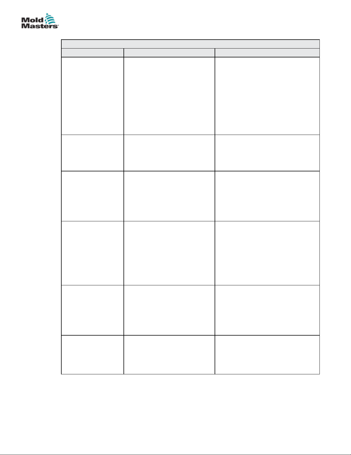
Table 3-3 Energy Forms, Energy Sources and General Lockout Guidelines
Energy Form Energy Source Lockout Guidelines
Electrical Energy • Power transmission lines
• Machine power cords
• Motors
• Solenoids
• Capacitors
(stored electrical energy)
Hydraulic Energy • Hydraulic systems
(e.g., hydraulic presses,
rams, cylinders, hammers)
Pneumatic Energy • Pneumatic systems
(e.g.,lines, pressure
reservoirs, accumulators, air
surge tanks, rams, cylinders)
Kinetic Energy
(Energy of a moving
object or materials.
Moving object may
be powered or
coasting)
Potential Energy
(Stored energy that
an object has the
potential to release
due to its position)
Thermal Energy • Supply lines
• Blades
• Flywheels
• Materials in supply lines
• Springs
(e.g., in air brake cylinders)
Actuators
• Counterweights
• Raised loads
• Top or movable part of a
press or lifting device
• Storage tanks and vessels
• Turn o power at machine rst (i.e.,
at point of operation switch), and
then at the main disconnect switch
for the machine.
• Lock and tag the main disconnect
switch.
• Fully discharge all capacitative
systems (e.g., cycle machine
to drain power from capacitors)
according to the manufacturer’s
instructions.
• Shut o, lock (with chains, built-
in lockout devices, or lockout
attachments) and tag valves.
• Bleed o and blank lines as
necessary.
• Shut o, lock (with chains, built-
in lockout devices, or lockout
attachments) and tag valves.
• Bleed o excess air.
• If pressure cannot be relieved,
block any possible movement of
machinery.
• Stop and block machine parts (e.g.
stop ywheels and ensure that they
do not recycle).
• Review entire cycle of mechanical
motion, ensure that all motions are
stopped.
• Block material from moving into
area of work.
• Blank as necessary.
• If possible, lower all suspended
parts and loads to the lowest (rest)
position.
• Block parts that might be moved by
gravity.
• Release or block spring energy.
• Shut o, lock (with chains, built-
in lockout devices, or lockout
attachments) and tag valves.
• Bleed o excess liquids or gases.
• Blank lines as necessary.
3-11
© 2020 Mold-Masters (2007) Limited. All Rights Reserved.
E-Multi Controller User Manual
Page 26
SAFETY
3.7 Grounded Earth Connections
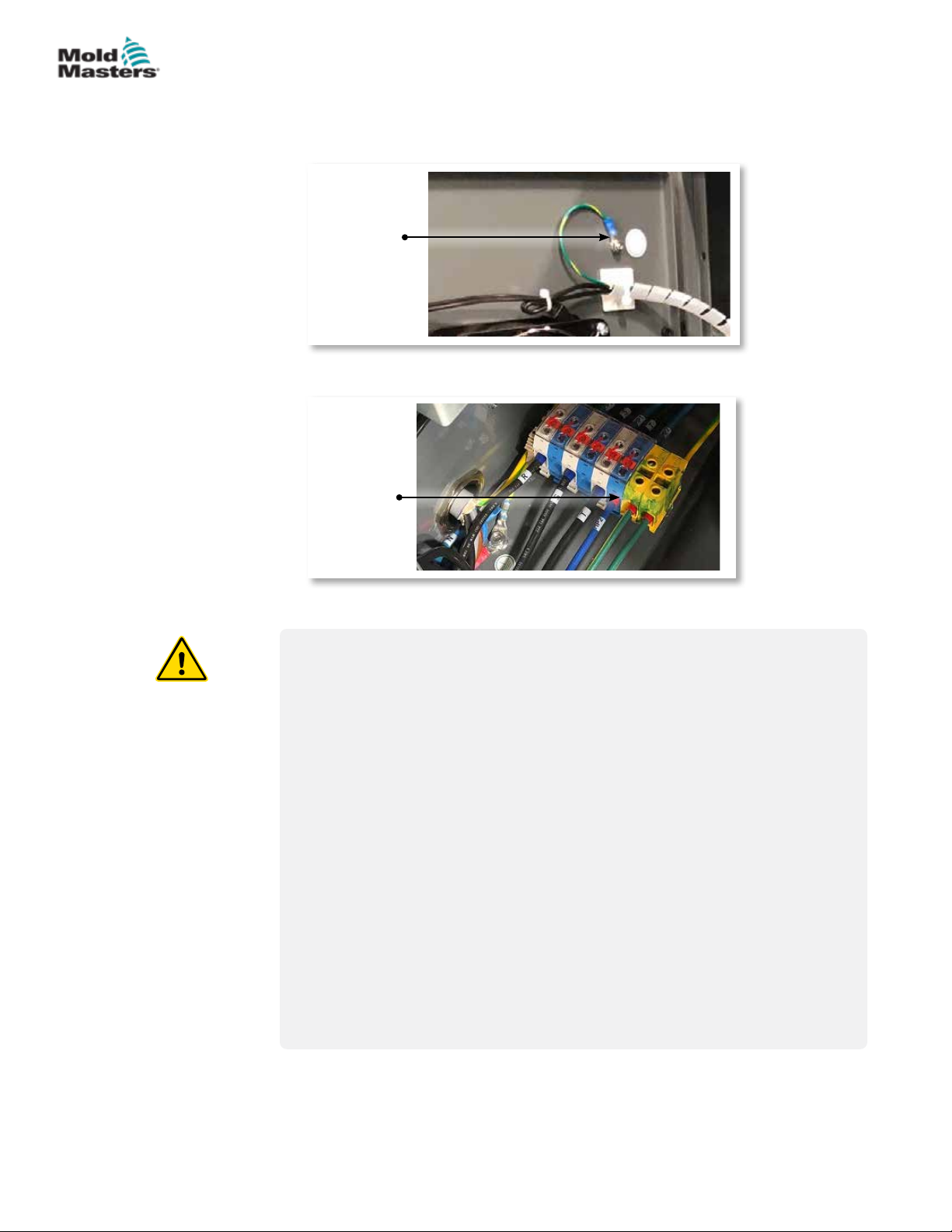
Grounded earth connections are found in the following locations on the
E-Multi controller:
Grounded
earth
wiring
Grounded
earth
wiring
3-12
3.8 Disposal
WARNING
Milacron Mold-Masters declines any responsibility for personal injury or
personal damage arising from reuse of the individual components, if these
parts are used other than for the original and proper intended purpose.
1. Hot runner and system components must be disconnected from the
power supply fully and properly before disposal, including electricity,
hydraulics, pneumatics and cooling.
2. Ensure that the system to be disposed of is free from uids. In the
case of hydraulic needle valve systems, drain the oil from the lines and
cylinders and dispose it in an environmentally responsible manner.
3. The electrical components are to be dismantled, separating them
accordingly as environmentally-friendly waste or disposed as hazardous
waste if necessary.
4. Remove the wiring. The electronic components are to be disposed in
accordance with the national electric scrap ordinance.
5. The metal parts are to be returned for metal recycling (waste metal
and scrap trade). The instructions of the corresponding waste disposal
company are to be observed in this case.
E-Multi Controller User Manual
Recycling of all possible materials should be at the forefront of the disposal
process.
© 2020 Mold-Masters (2007) Limited. All Rights Reserved.
Page 27

SAFETY
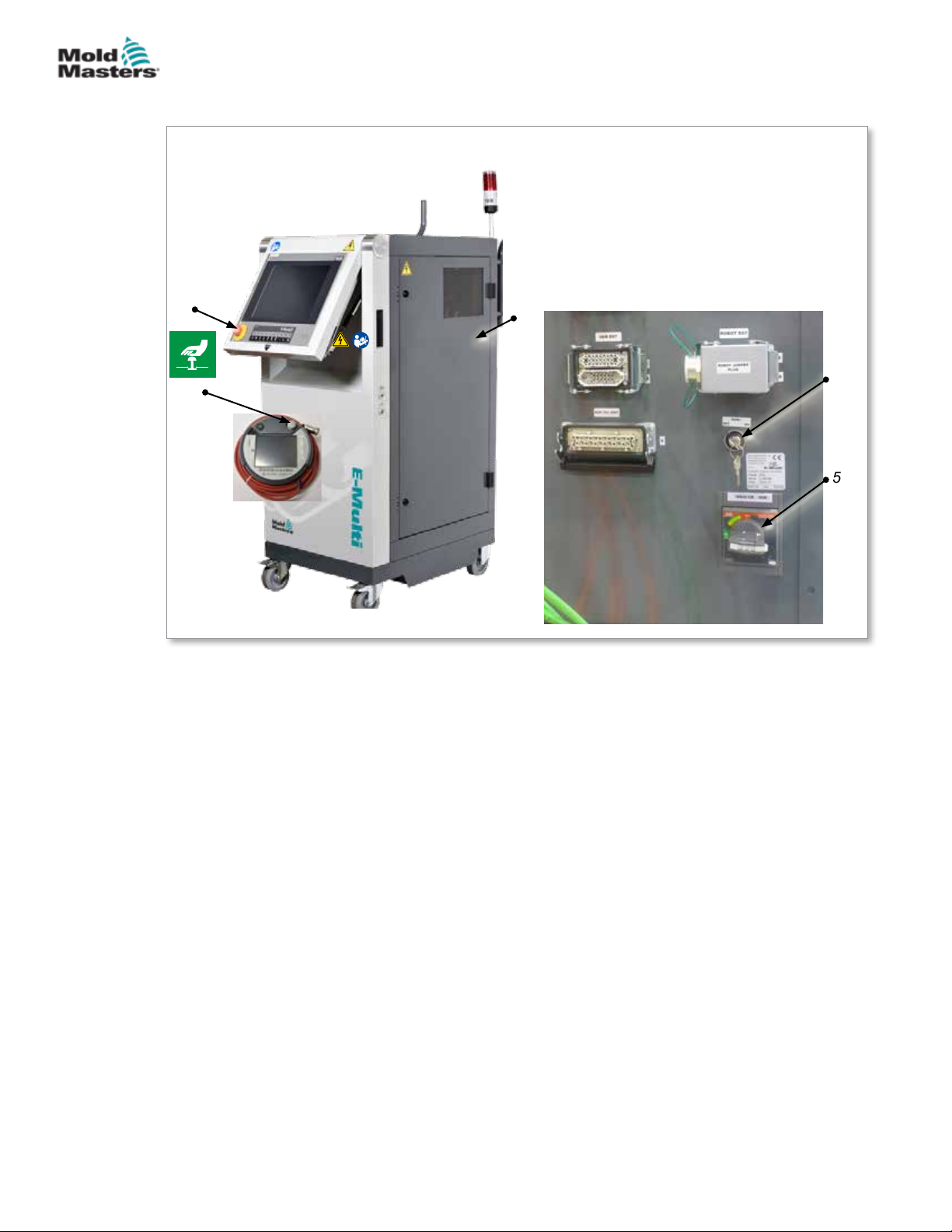
3.9 E-Multi Controller Safety Hazards
See also “Figure 3-2 E-Multi controller safety hazards” on page 3-14.
WARNING - ELECTRICAL SHOCK HAZARD
It is crucial to comply with these warnings to minimize any personal danger.
• Ensure that all energies are properly locked out in the controller and
molding machine before installation of the controller into the system.
• DO NOT enter the cabinet without rst ISOLATING the supplies OR
having a qualied person selecting the BYPASS SWITCH to ON, to gain
live access to the controller. There are unguarded terminals inside the
cabinet which may have a dangerous potential across them. Where a
three-phase supply is used, this potential may be up to 600VAC.
• With the BYPASS SWITCH set to OFF opening the high power section
of the controller will cause the circuit breaker to TRIP, disconnecting all
power to the cabinet.
• Voltage and amperage cables are connected to the controller and the
mold. There is also a voltage cable connection between the servo motor
and the controller. Electric power must be shut o and lockout / tagout
procedures followed prior to installing or removing any cables.
3-13
• Integration should be done by properly trained personnel based on local
codes and regulations. Electrical products may not be grounded when
removed from the assembled or normal operating condition.
• Do not mix electrical power cables with thermocouple extension
cables. They are not designed to carry the power load or list accurate
temperature readings in each other’s application.
WARNING
Do not make changes to the factory settings without the help of
Mold-Masters service personnel. Changes to these settings can result in
hazardous out-of-control or unexpected movement. It can also damage the
machine and voids the warranty.
3.9.1 Operational Environment
The E-Multi controller should be installed in a clean, dry environment where
the ambient conditions do not exceed the following limits:
- Temperature: +5 to +45°C
- Relative Humidity: 90% (non-condensing)
3.9.2 Cabinet Push / Tip Forces
Force required to move
cabinet on castors
Force required to tip
cabinet if one castor is
missing
© 2020 Mold-Masters (2007) Limited. All Rights Reserved.
Table 3-4 Cabinet Push / Tip Forces
EM1 / EM2 / EM3 Cabinet EM4 Cabinet
13 lbs (6KG F) 35 lbs (16KG F)
150lbs (68KG F) 200 lbs (91KG F)
E-Multi Controller User Manual
Page 28
SAFETY
E-Multi Controller Safety Hazards - continued
1. Side access panel (live
components inside)
2. Emergency stop button
3. E-Multi stop button
4. Bypass switch
5. Main power switch
3-14
2
3
Figure 3-2 E-Multi controller safety hazards
1
4
5
E-Multi Controller User Manual
© 2020 Mold-Masters (2007) Limited. All Rights Reserved.
Page 29
SAFETY
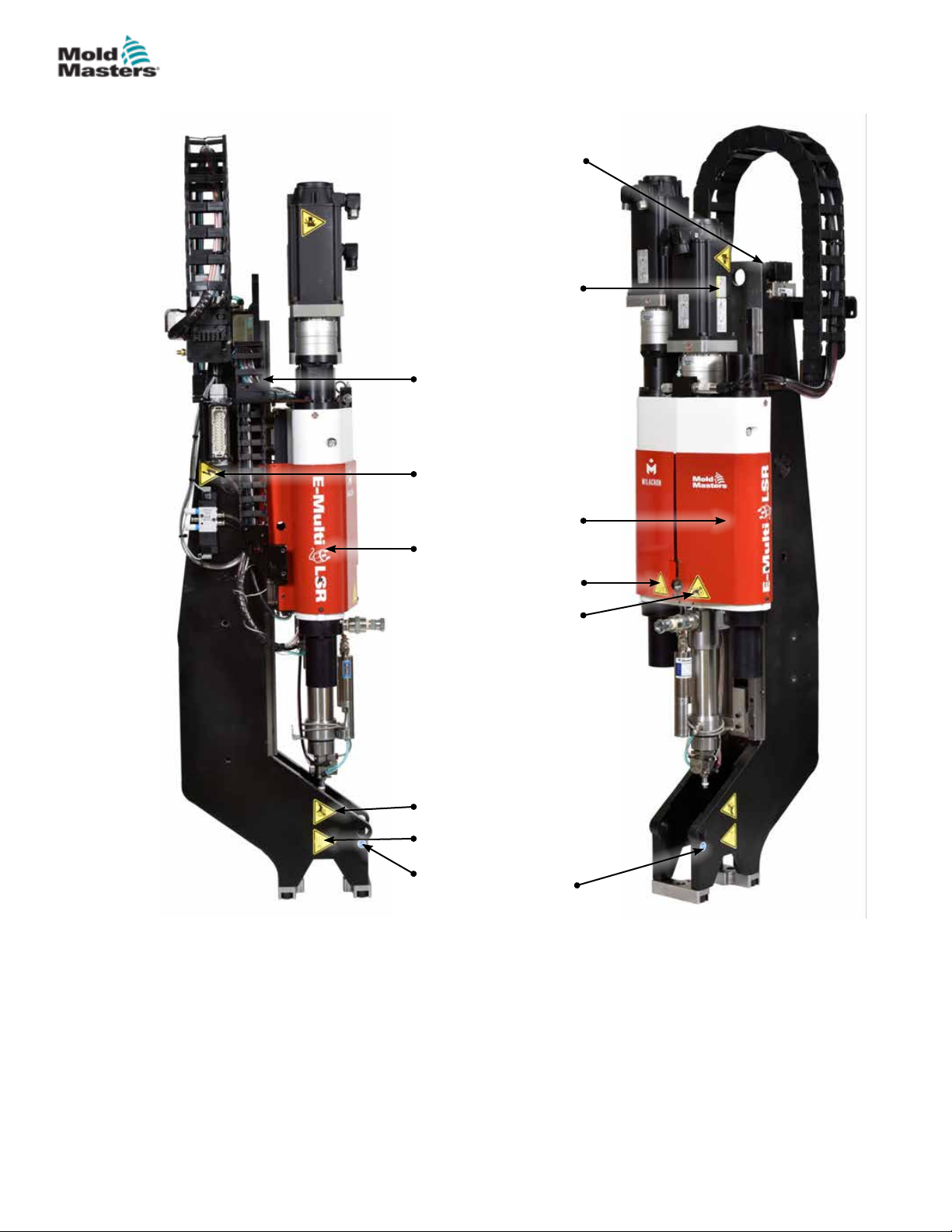
3.10 E-Multi Injection Unit Safety Labels
Mandatory lift point
(not visible here)
Body crushing
hazard
Hot surface
hazard
Read manual (not
visible here)
Electrical shock
hazard
3-15
Rear cover
Splashing hazard
Entanglement
hazard (belt drive)
Pinch point hazard
Splashing hazard
Mandatory lift point
Figure 3-3 E-Multi injection unit safety labels
Front cover
Please refer to “Table 3-6 Safety Symbols Used on the E-Multi Injection Unit”
on page 3-18 for full hazard descriptions.
© 2020 Mold-Masters (2007) Limited. All Rights Reserved.
E-Multi Controller User Manual
Page 30
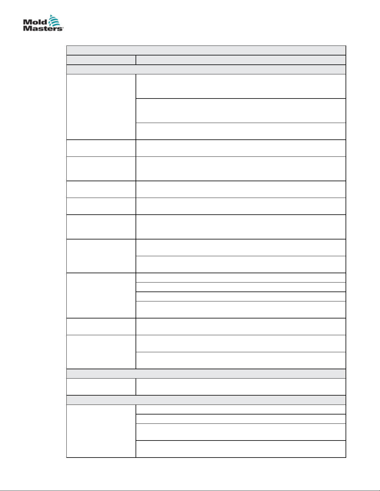
SAFETY
3.11 E-Multi Injection Unit Safety Hazards
Table 3-5 E-Multi Injection Unit Safety Hazard Details
Hazard Type Potential Hazards
Mechanical Hazards
Body Crushing
Hazard
Shearing Hazard A possible shearing hazard exists between the edge of the injection guard
Cutting Hazard For horizontally-mounted machines with a high center line height, a
Entanglement Hazard
(Belt Drive)
Entanglement Hazard The open feed port could present an entanglement hazard. Always keep
Cutting or Severing
Hazard
High Pressure Fluid
or High Temperature
Molten Material
Splashing Hazard
Loss of Stability Injection unit could fall over if improperly installed on stand.
Trip Hazard Controller cables are a tripping hazard on the oor between the controller
Stored Energy There could be stored energy in compressed material which is not
Electrical Hazard
Contact of Persons
with High Voltage
Thermal Hazards
Possible Contact of
Persons with High
Temperature Material
End of motor moves back during operation. A hazard may exist between
the end of the injection unit motor assembly and a nearby solid obstacle.
Ensure proper guarding as part of integration.
During installation of the E-Multi injection unit onto a mold, a crushing
hazard exists between the adapter plate and the mounting surface of the
mold.
A crushing hazard exists between nozzle and mold melt inlet during
carriage forward motion.
and the injection housing during injection.
person's head could hit the end of the injection unit causing a cut. Ensure
proper guarding.
A person could become entangled in the drive belt or screw of the injection
unit. Always keep guards in place.
guards in place.
For units equipped with a servo carriage, a severing hazard may exist
between the barrel assembly and support beam when the carriage moves
forward and the hard stop extension in the trunnion slot is not installed.
High pressure uid or high temperature molten material may spray from
the nozzle. Always use personal protective equipment (PPE).
High pressure material or high temperature molten material may spray
from a blocked feed port. Always use personal protective equipment.
Injection unit could fall over if transported on stand castors.
Injection unit could fall from top of mold if not properly secured.
Injection unit could fall over if stored vertically on the oor or a table
without adequate support.
and the press or E-Multi injection unit.
released when the machine is powered o.
When installed vertically and powered o, there is stored energy in the
injection assembly which could move downwards.
Heaters, servo motors and electrical components in the controller could
come in contact with a person. Do not remove covers when energized.
The injection barrel could result in burns.
Melted material during routine purging could cause burns.
Hot material or gases could be released from the feed port when clearing
a blockage.
The electric servo motors could overheat presenting a hot surface which
could cause burns to someone touching it.
3-16
E-Multi Controller User Manual
© 2020 Mold-Masters (2007) Limited. All Rights Reserved.
Page 31
SAFETY
E-Multi Injection Unit Safety Hazards - continued
Table 3-4 E-Multi Injection Unit Safety Hazard Details
Hazard Type Potential Hazards
Hazards Generated By Materials or Substances
Hazards from Contact
With or Inhalation of
Harmful Gases
Fire or Explosion
Hazard
Ergonomic Hazards
Lift Hazard Attempting to lift or support the unit during installation could result in
Combination Hazards
Failure / Disorder of
Control System
Errors of Fitting Incorrect design of the adapter plate, or tool interface or attachment, or
Hot material could result in harmful gases being emitted from the purged
material, feed inlet or mold.
Hot surfaces of the barrel heaters could ignite ammable liquids or dust.
injury.
Incorrect connections can result in out-of-control or unexpected
movement causing damage to the machine and a possible hazard.
improper torquing of mounting fasteners may result in a failure of the
connection and subsequent loss of stability or falling of the machine.
3-17
© 2020 Mold-Masters (2007) Limited. All Rights Reserved.
E-Multi Controller User Manual
Page 32

SAFETY
3.12 E-Multi Injection Unit Safety Symbols
Table 3-6 Safety Symbols Used on the E-Multi Injection Unit
Symbol General Description
General – Warning
Indicates an immediate or potentially hazardous situation, which if not
avoided, could result in a serious injury or death, and / or damage to
equipment.
Warning – Body Crush Hazard
End of motor moves back during hold or recovery. Hazard may exist
between the end of the injection unit motor assembly and a nearby solid
obstacle.
Warning – Tip Over Hazard
Injection unit could tip over when installed on stand or if stored vertically on
the oor or a table without adequate support.
Warning – Electric Shock Hazard
Contact with hazardous voltages will cause death or serious injury. Turn o
power and review electrical schematics before servicing equipment. May
contain more than one live circuit. Test all circuits before handling to make
sure circuits have been de-energized.
Warning – Hot Surface Hazard
Contact with exposed hot surfaces will cause serious burn injury. Wear
adequate personal protective equipment (PPE) when working near these
areas.
Warning – Entanglement Hazard (Belt Drive)
A person could become entangled in the drive belt of the injection unit.
Always keep guards in place.
3-18
Warning - Pinch Point Hazard
A pinch point exists in this area which could result in a pinching, crushing
or shearing injury to a person.
Warning – Splashing Hazard
Material or high pressure gas can cause death or severe burns. Wear
personal protective equipment (PPE) while servicing the feed throat,
nozzle, mold areas, and when purging the injection unit.
Mandatory – Read Service Manual Before Operation
Personnel should read and understand all instructions in the manuals
before working on equipment. Only properly trained personnel should
operate the equipment.
Mandatory Lift Points
Mandatory lift points must be used. If wrong lift points are used the unit
could become unstable when being moved.
E-Multi Controller User Manual
© 2020 Mold-Masters (2007) Limited. All Rights Reserved.
Page 33
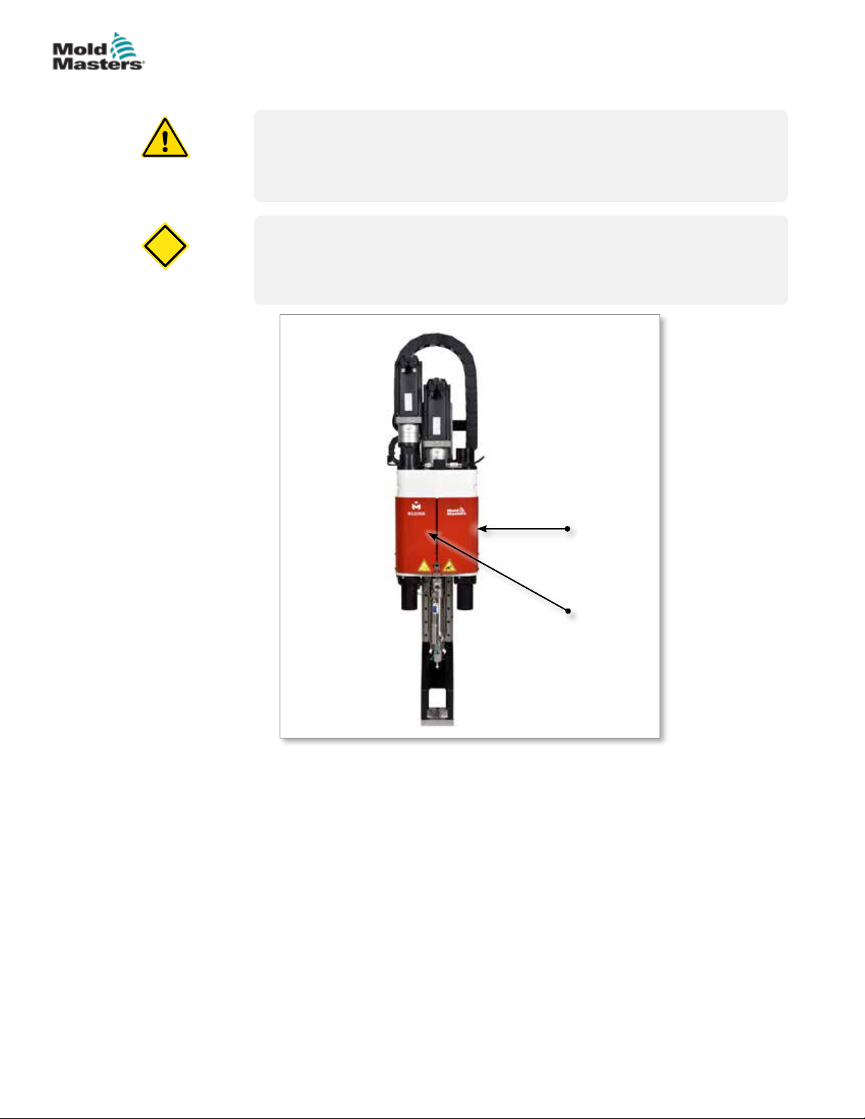
CAUTION
SAFETY
3.13 E-Multi Injection Unit Safety Guards
WARNING
Guards should not be removed unless maintenance is required and should
be replaced after maintenance is complete. Do not run the machine with
guards removed.
CAUTION
When installing the machine guards (front and rear covers) and the barrel
covers, check that they do not pinch water lines, air lines or thermocouple
wires when the unit moves.
3-19
Figure 3-4 Guards layout
Front
cover
Rear
cover
© 2020 Mold-Masters (2007) Limited. All Rights Reserved.
E-Multi Controller User Manual
Page 34
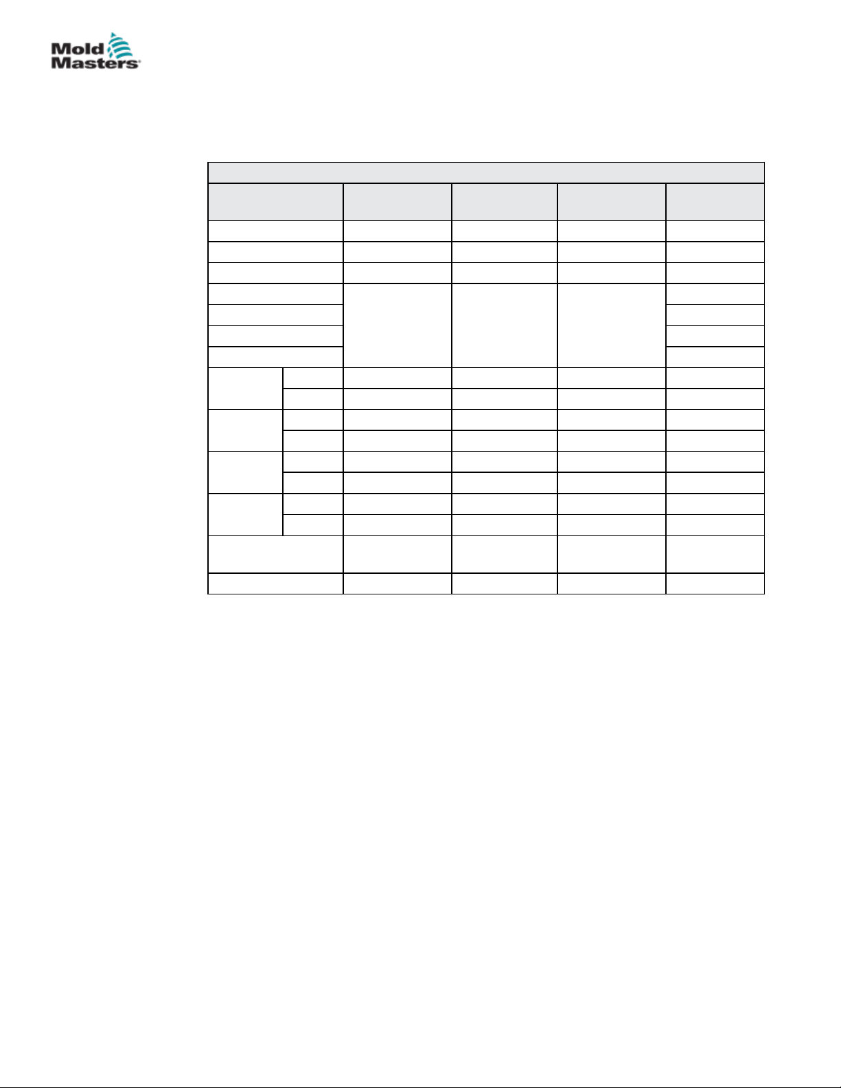
SAFETY
3.14 E-Multi Weight Specications
Dimensions and weights shown are for packed wooden crates containing
standard-optioned units. Additional options may add weight or require
additional crates. Specications subject to changes without notice.
Table 3-7 E-Multi Injection Unit Shipping Dimensions and Weight
Model Length mm
(in.)
EM1/EM2 1520 (60) 740 (29) 840 (33) 300 (660)
EM3 2080 (82) 840 (33) 910 (36) 500 (1100)
EM4 3302 (130) 914 (36) 991 (39) 1300 (2860)
ER1-15
ER1-30 400 (880)
ER2-50 400 (880)
ER2-80 500 (1100)
ER3-100
ER3-200
ER4-350
ER4-550
EM1/EM2/EM3
Controllers
EM4 Controller 1880 (74) 788 (31) 1626 (64) 600 (1330)
Crate 1 3302 (130) 914 (36) 991 (39) 900 (1980)
Crate 2 1543 (61) 975 (38) 670 (26) 700 (1540)
Crate 1 3302 (130) 914 (36) 991 (39) 900 (1980)
Crate 2 1543 (61) 975 (38) 670 (26) 700 (1540)
Crate 1 3302 (130) 914 (36) 991 (39) 1200 (2640)
Crate 2 1543 (61) 975 (38) 670 (26) 700 (1540)
Crate 1 3302 (130) 914 (36) 991 (39) 1300 (2860)
Crate 2 1543 (61) 975 (38) 670 (26) 700 (1540)
1632 (64) 932 (37) 1056 (42)
1702 (67) 788 (31) 1626 (64) 390 (860)
Width mm
(in.)
Height mm
(in.)
Weight kg
(lb)
400 (880)
3-20
E-Multi Controller User Manual
© 2020 Mold-Masters (2007) Limited. All Rights Reserved.
Page 35
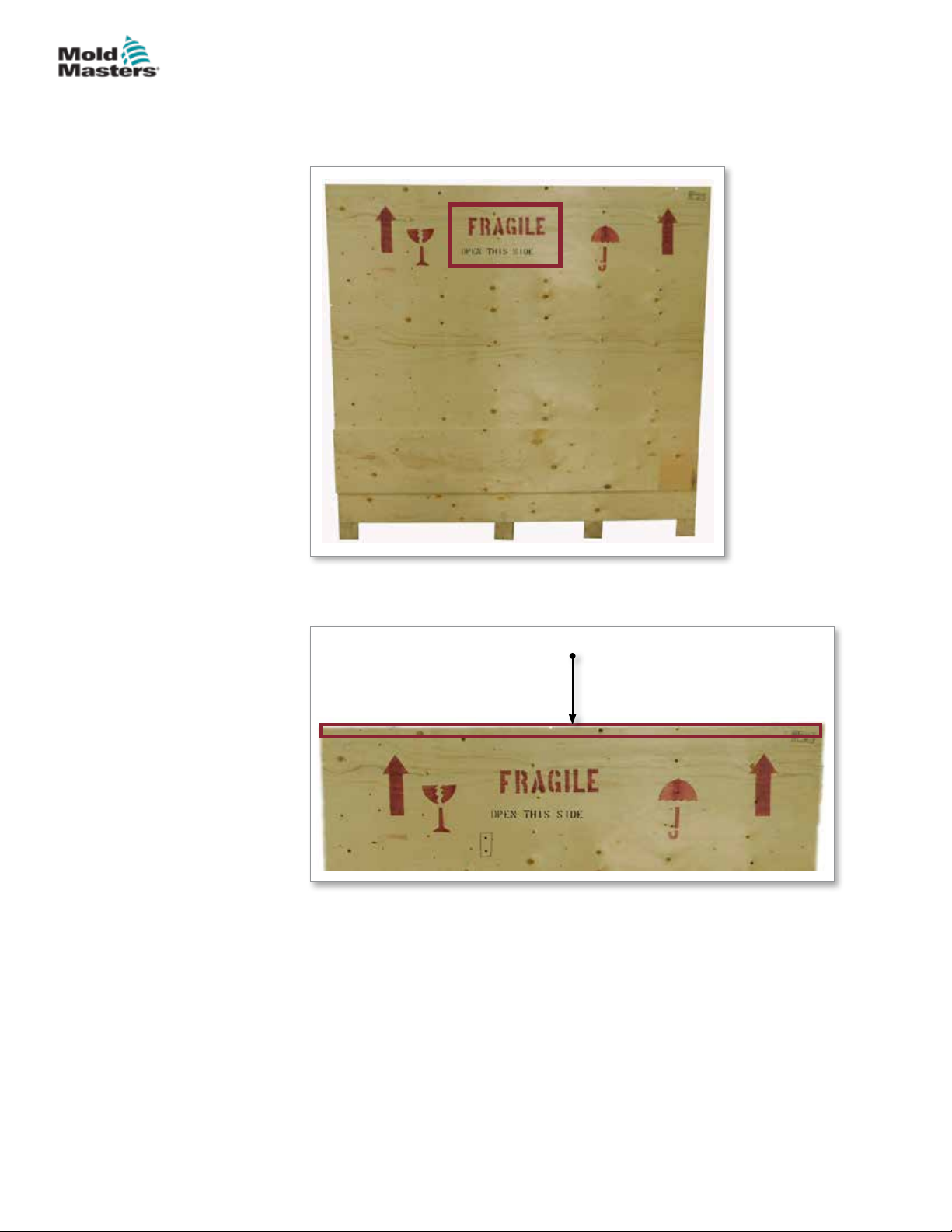
SAFETY
3.15 Unpack the E-Multi Controller
1. Identify the correct side of the crate to open. This side is marked with the
phrase “FRAGILE OPEN THIS SIDE”. See Figure 3-5.
3-21
Figure 3-5 Correct side of crate to open
2. Remove top row of screws from the long side of the crate. See Figure 3-6.
Remove top row of screws
Figure 3-6 Remove top row of screws
3. Remove screws from top of crate and remove the top of the crate.
© 2020 Mold-Masters (2007) Limited. All Rights Reserved.
E-Multi Controller User Manual
Page 36
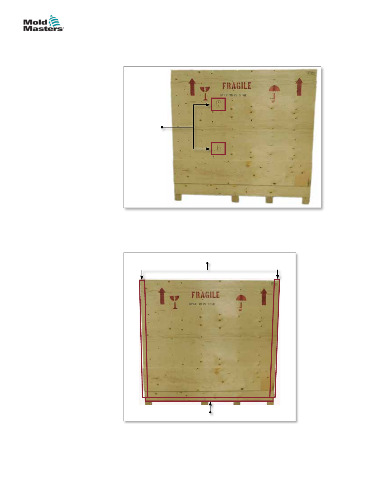
SAFETY
Unpack the E-Multi Controller - continued
4. From the side of the crate marked with “FRAGILE OPEN THIS SIDE”,
remove the cross brace screws. See Figure 3-7.
Remove
cross brace
screws
3-22
Figure 3-7 Remove cross brace screws
5. From the side of the crate marked with “FRAGILE OPEN THIS SIDE”,
remove the screws down the sides and at the bottom of the crate. See
Figure 3-8.
Remove screws along sides
E-Multi Controller User Manual
Remove screws along bottom
Figure 3-8 Remove screws from side and bottom
6. Remove the side of the crate marked with “FRAGILE OPEN THIS SIDE”.
7. Remove the remaining four screws holding the braces on the opposite
side of the crate and remove the braces.
© 2020 Mold-Masters (2007) Limited. All Rights Reserved.
Page 37
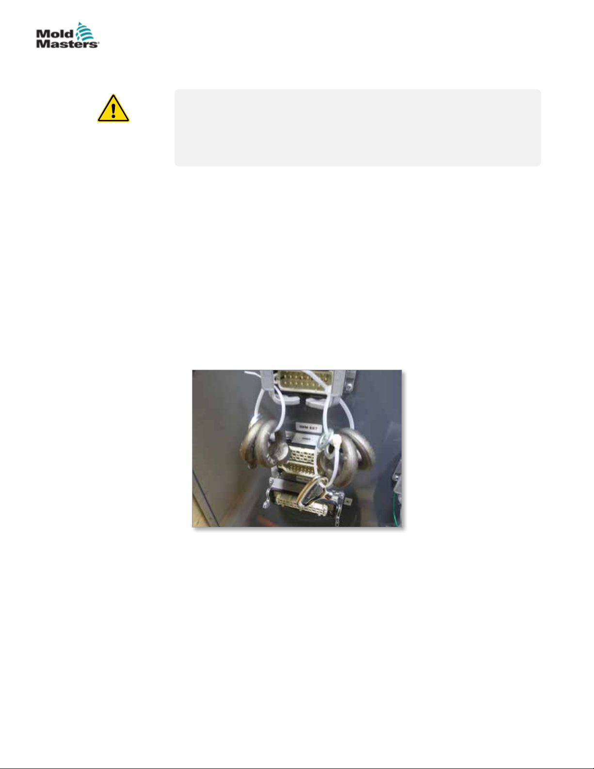
SAFETY
3.16 Lift the E-Multi Controller
3.16.1 Preparation
WARNING
Always ensure that all lifting devices are in good repair and of adequate
capacity before commencing work. Failure to lift or support the controller
properly can result in severe injury or death and / or damage to the
controller.
1. Choose lift equipment that is rated for the prescribed load.
2. Dene the load path: the path and orientation the item will move in while
it is being lifted, and the location and orientation where it will be set down.
3. Identify and avoid potential pinch points: where an individual or a
component of the lifting equipment or load may be caught between two
surfaces.
4. Secure and remove all boxes and accessories from the crate and store in
a safe location away from the lift path.
5. Remove all cables not attached to the controller from the crate and store
in a safe location away from the lift path.
3-23
The E-Multi controller is shipped with four eyebolts with threaded studs and
four washers. These components are attached to the keys at the back of the
controller. See Figure 3-9.
Figure 3-9 Eyebolts and washers
© 2020 Mold-Masters (2007) Limited. All Rights Reserved.
E-Multi Controller User Manual
Page 38
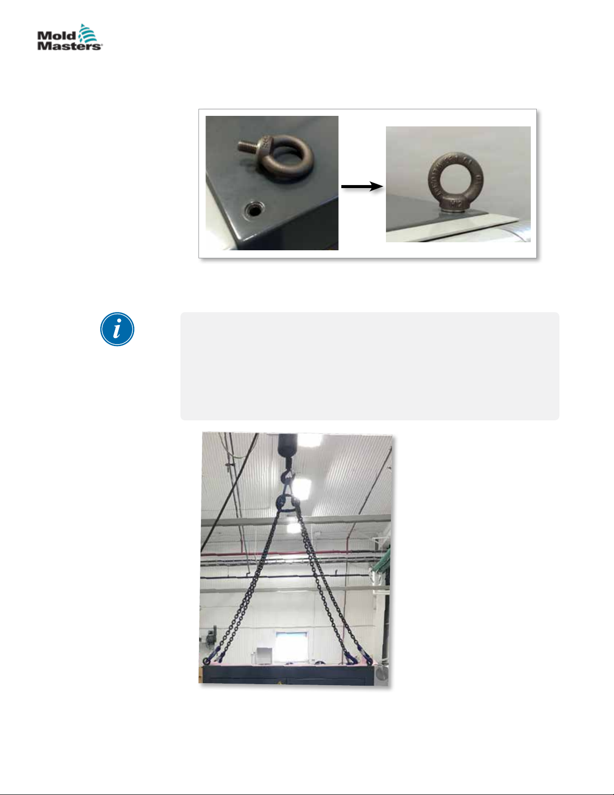
SAFETY
Unpack the E-Multi Controller - continued
6. Assemble eyebolts and washers and install into the holes on the top of
the E-Multi controller. See Figure 3-10.
Figure 3-10 Install eyebolts and washers
7. Attach slings to all of the eyebolts. See Figure 3-5.
IMPORTANT
3-24
Slings must be attached securely to all four eyebolts.
Balance the load in the chain or lifting device before it is lifted more than a
few inches.
Minimize swinging by bringing the hook over the load appropriately.
Move powered hoists slowly into engagements with loads.
E-Multi Controller User Manual
Figure 3-11 Attach slings to all four eyebolts
8. Lift the E-Multi controller from the crate.
© 2020 Mold-Masters (2007) Limited. All Rights Reserved.
Page 39
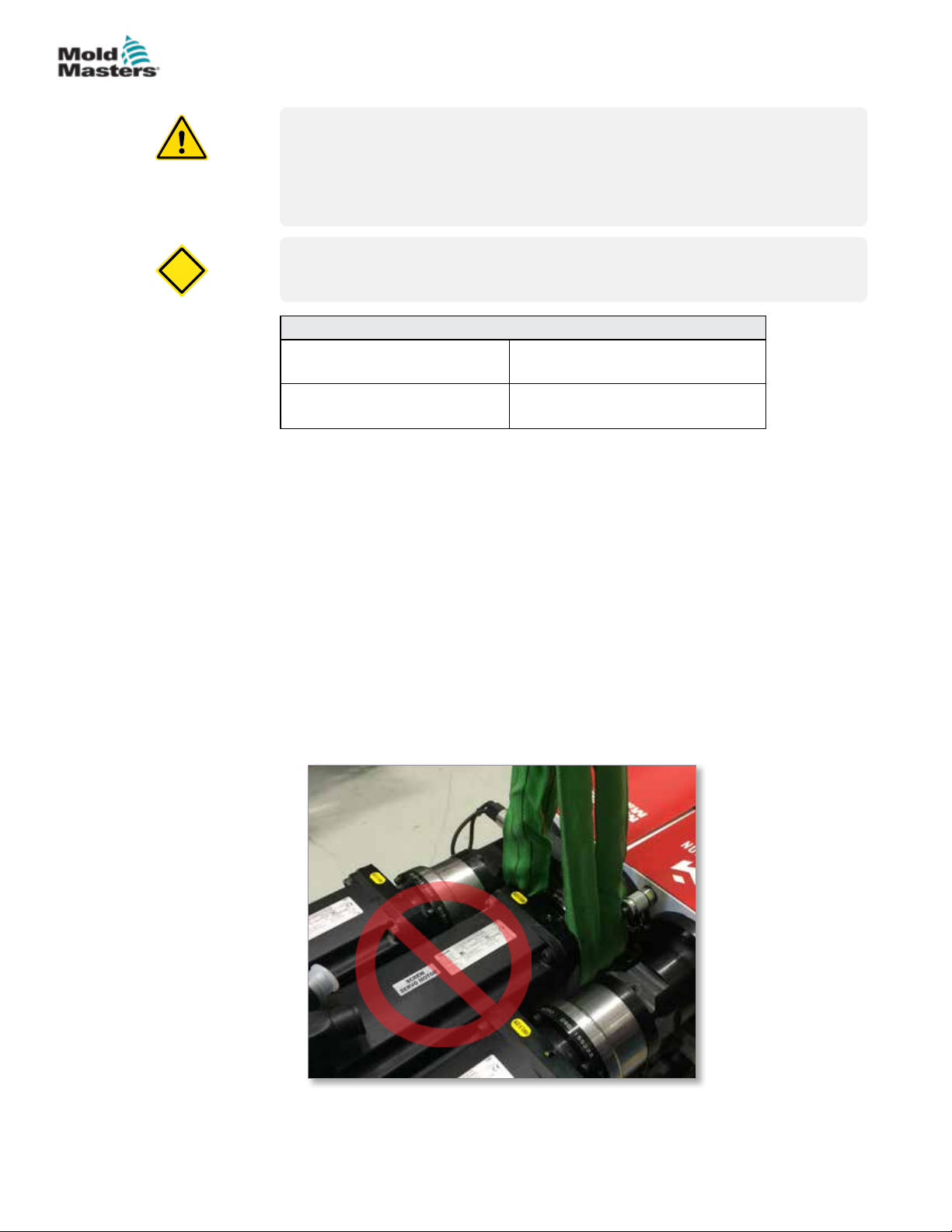
CAUTION
SAFETY
3.17 Lift the E-Multi Injection Unit
WARNING
When doing any work on the machine that requires lifting the machine,
connect all lifting devices and support the machine using a crane of
adequate capacity before commencing work. Failure to support the
machine can result in severe injury or death.
CAUTION
Do not use the motor as a lifting point.
Table 3-8 E-Multi Injection Unit Lifting Kits
EM1/EM2
EM3
3.17.1 Prior to Lifting the E-Multi Injection Unit
1. Choose lift equipment that is rated for the prescribed load. See equipment
tag.
2 x 16 mm (5/8 in.) bow shackles
2 x 1220 mm (48”) slings
2 x 25 mm (1 in.) bow shackles
2 x 1830 mm (72”) slings
3-25
2. Dene the load path: the path and orientation the item will move in while
it is being lifted, and the location and orientation where it will be set down.
3. Use recommended attachment points only. See Section 3.17.
4. Identify and avoid potential pinch points: where an individual or a
component of the lifting equipment or load may be caught between two
surfaces.
5. Secure and balance the load in the chain or lifting device before it is lifted
more than a few inches.
6. Minimize swinging by bringing the hook over the load appropriately.
7. Move powered hoists slowly into engagements with loads.
Figure 3-12 Do not use the motor as a lifting point
© 2020 Mold-Masters (2007) Limited. All Rights Reserved.
E-Multi Controller User Manual
Page 40
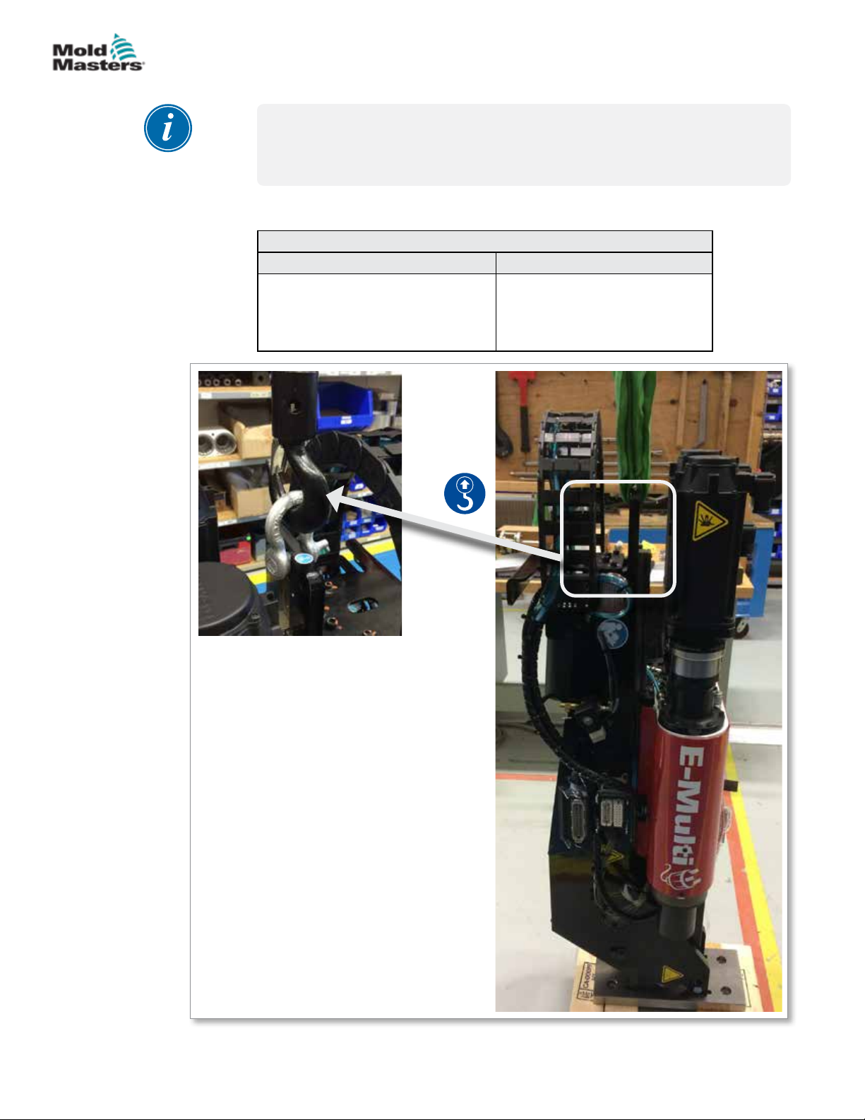
SAFETY
3.18 EM1 / EM2 / EM3 Lift Connections
NOTE
Review the information in Section 3.14 before performing any lifting
procedure.
3.18.1 EM1 / EM2 / EM3 Vertical Lift Connections
Table 3-9 EM1 / EM2 / EM3 Vertical Lift Connections
EM1 / EM2 EM3
Connect sling to motor end of the
support beam using one 16 mm (5/8
in.) shackle in lifting hole.
Connect sling to motor end
of the support beam using a
25 mm (1 in.) shackle in lifting
hole.
3-26
E-Multi Controller User Manual
© 2020 Mold-Masters (2007) Limited. All Rights Reserved.
Page 41
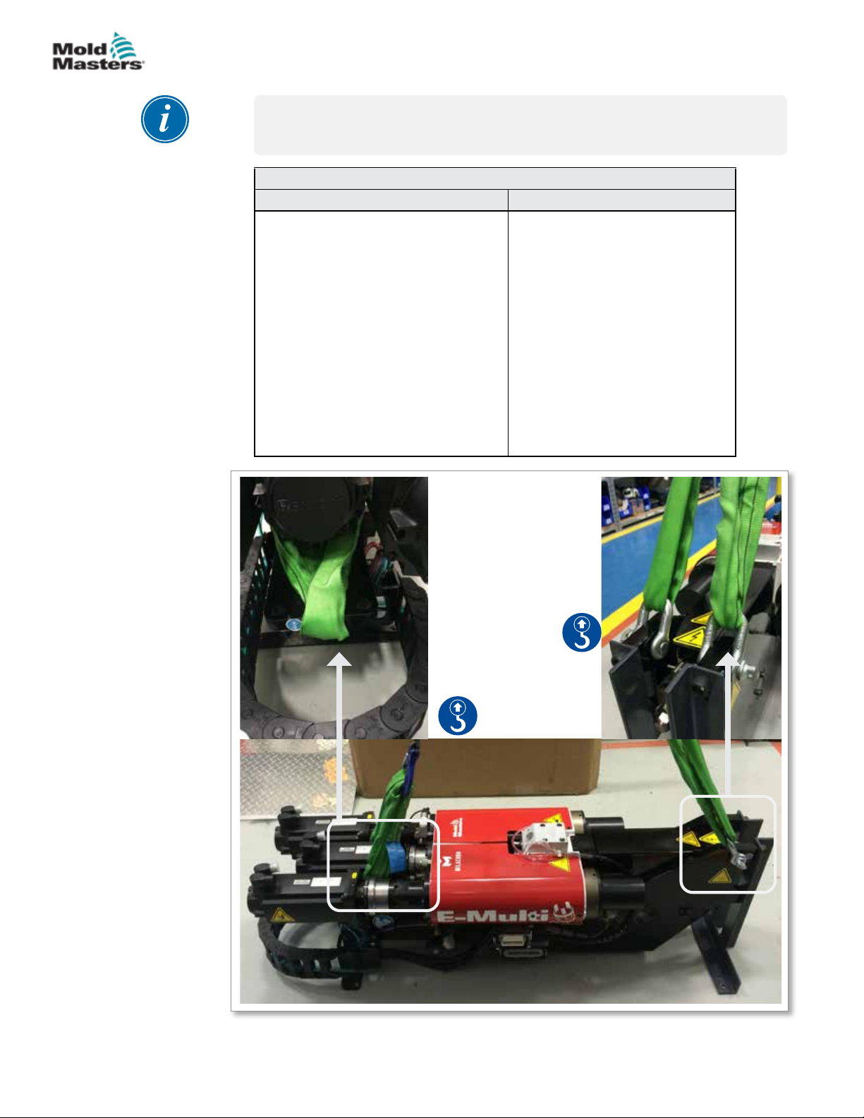
SAFETY
3.18.2 EM1 / EM2 / EM3 Horizontal Lift Connections
NOTE
For best results use an adjustable two leg chain bridle.
Table 3-10 EM1 / EM2 / EM3 Horizontal Lift Connections
EM1 / EM2 EM3
Connect one sling (A) to motor end of
the support beam by feeding it through
the lifting hole, with sling on either side
of the motor.
Connect other sling (B) to barrel end
of the support beam using two 16 mm
(5/8 in.) shackles in the lifting holes.
NOTE: EM1 / EM2 units require
blocks or shipping brackets when set
down horizontally to prevent damage
to the linear actuator.
Connect one sling (A) to motor
end of the support beam by
feeding it through the lifting hole,
with sling on either side of the
motor.
Connect other sling (B) to barrel
end of the support beam using two
25 mm (1 in.) shackles in lifting
holes.
3-27
A
© 2020 Mold-Masters (2007) Limited. All Rights Reserved.
B
E-Multi Controller User Manual
Page 42

SAFETY
3.19 E-Multi Injection Unit Stand Safety
WARNING
The stands are intended for supporting E-Multi injection units at the
machine when used in the horizontal position. They are not for transporting
the E-Multi injection unit and would be top heavy and present a tip hazard.
The E-Multi injection unit and stand assembly should be moved together by
crane using the proper E-Multi injection unit lift points.
Do not modify stands to reduce or add height, e.g. adding additional holes
or not bolting the upper and lower columns together. Such changes would
impact the stand stability and could result in serious injury as well as
damage to the machine.
3-28
E-Multi Controller User Manual
© 2020 Mold-Masters (2007) Limited. All Rights Reserved.
Page 43
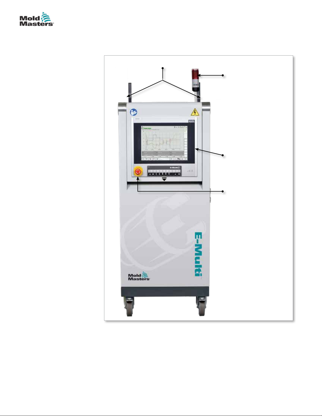
OVERVIEW
Section 4 - Overview
4.1 Controller Front
1
2
3
4-1
Figure 4-1 Controller front
4
1. Lifting rings
2. Alarm indicator light
3. Human machine
interface (HMI)
4. Emergency stop button
© 2020 Mold-Masters (2007) Limited. All Rights Reserved.
E-Multi Controller User Manual
Page 44
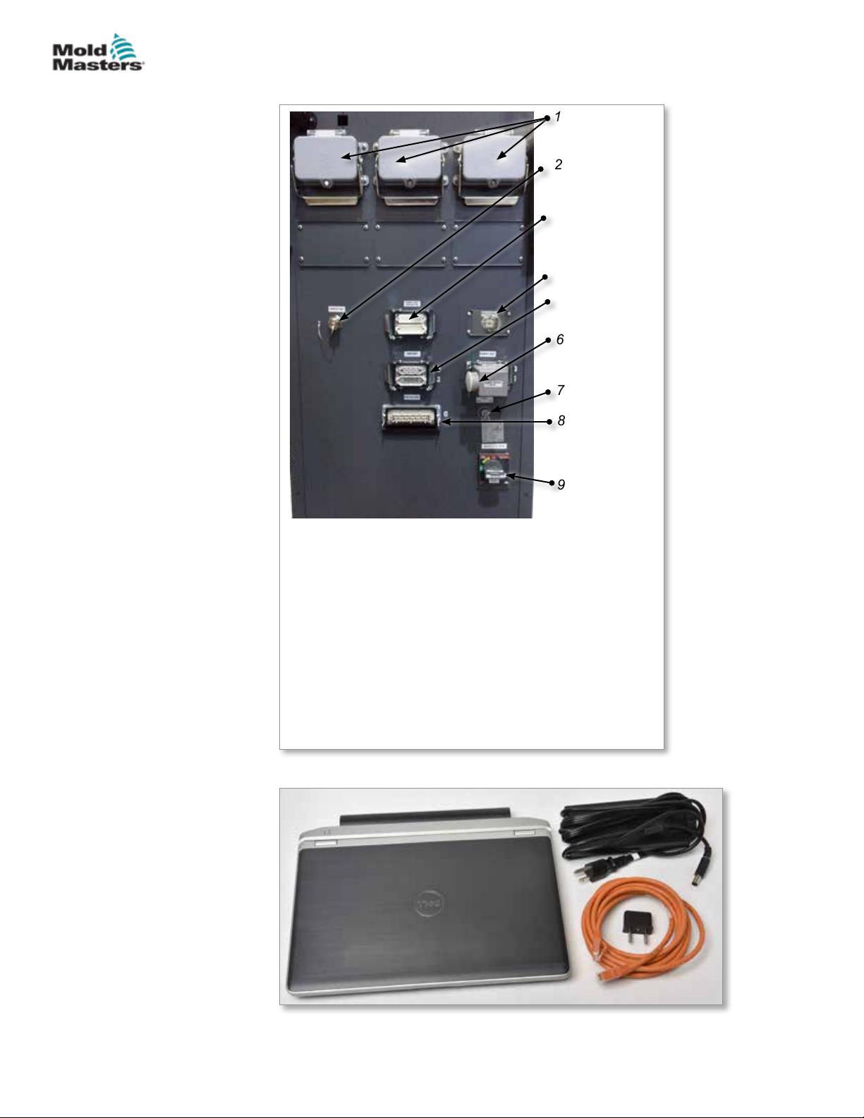
OVERVIEW
4.2 Controller Back - Connections Side
1
2
3
4
5
6
7
8
4-2
9
1. Zone connections for hot runner control option
2. Remote HMI connection
3. Barrel heater and thermocouple connection
4. Heat exchanger power
5. IMM E67 connection
6. E67 connection to robot. Jumper plug installed.
7. Bypass switch
8. Auxiliary injection unit connection
9. Main on / o power switch (circuit breaker)
Figure 4-2 Controller back connections
E-Multi Controller User Manual
Figure 4-3 Diagnostic kit (option)
© 2020 Mold-Masters (2007) Limited. All Rights Reserved.
Page 45
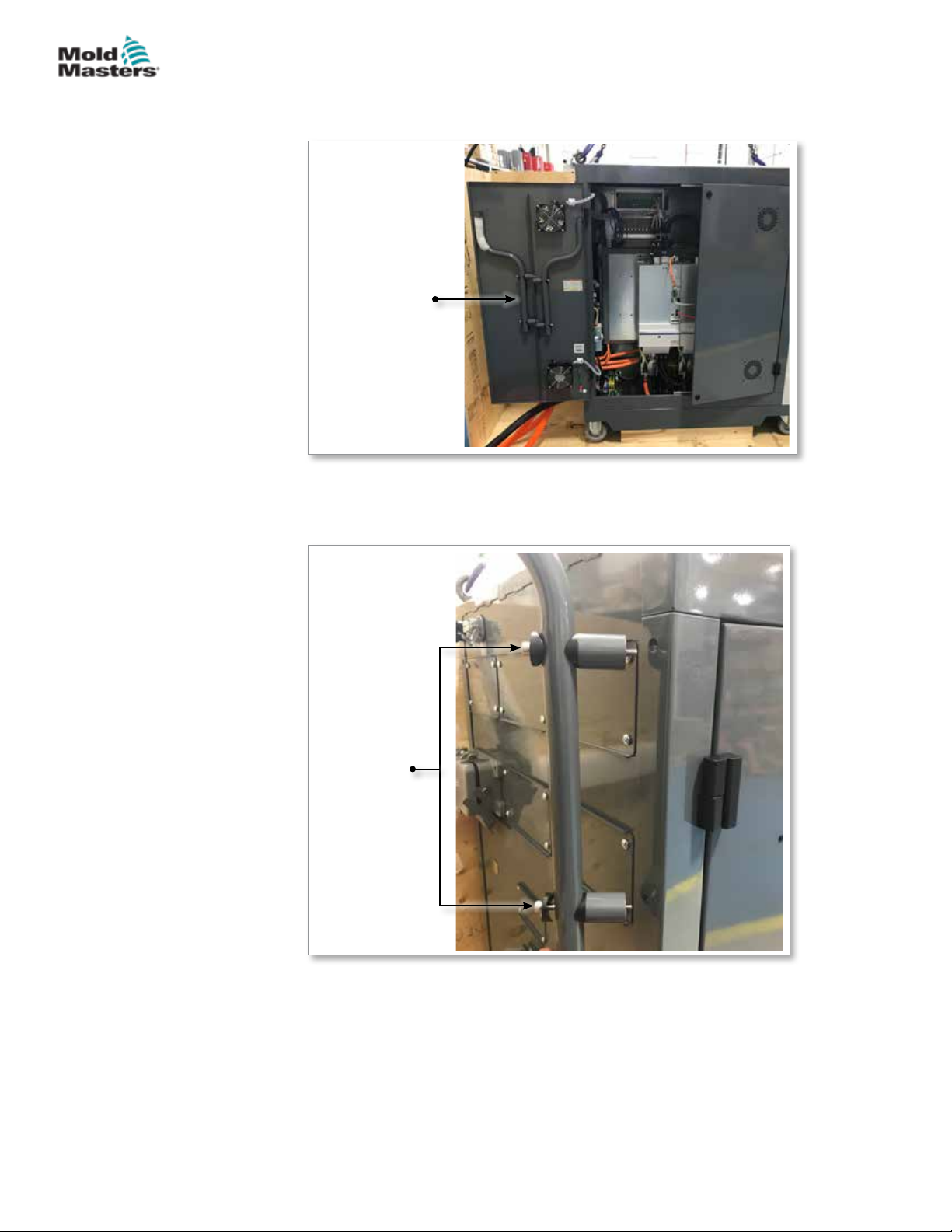
OVERVIEW
4.3 Cable Holders
The E-Multi controller is supplied with cable holders. See Figure 4-4.
Cable holders
Figure 4-4 Cable holders
4-3
They can be attached to the back of the cabinet to use for cable storage.
See Figure 4-5.
Cable holders
attach to rear
of cabinet
Figure 4-5 Attach cable holders
© 2020 Mold-Masters (2007) Limited. All Rights Reserved.
E-Multi Controller User Manual
Page 46

OVERVIEW
4-4
E-Multi Controller User Manual
© 2020 Mold-Masters (2007) Limited. All Rights Reserved.
Page 47

INSTALLATION
Section 5 - Installation
5.1 Introduction
WARNING
Ensure that you have fully read “Section 3 - Safety” before connecting or
operating the controller.
It is the responsibility of the integrator to understand and follow international
and local standards for safety of machinery when integrating the controller
with the molding system.
The E-Multi controller should be located in such a way that the main
disconnect is easily accessible in case of emergency.
The E-Multi controller is shipped with a power cable which is a correct size
to run the system. When you install a connector on the cable, ensure that
the connector can safely withstand the full system load.
The E-Multi controller supply should have a fused disconnect or main circuit
breaker according to local safety codes. Refer to the serial plate on the
controller cabinet for conrmation of the supply requirements. If the local
supply is outside the specied range, please contact Mold-Masters for
advice.
5-1
WARNING - ELECTRICAL SHOCK HAZARD
It is crucial to comply with these warnings to minimize any personal danger.
• Ensure that all energies are properly locked out in the controller and
molding machine before installation of the controller into the system.
• DO NOT enter the cabinet without rst ISOLATING the supplies OR
having a qualied person selecting the BYPASS SWITCH to ON, to gain
live access to the controller. There are unguarded terminals inside the
cabinet which may have a dangerous potential across them. Where a
three-phase supply is used, this potential may be up to 600VAC.
• With the BYPASS SWITCH set to OFF opening the high power section
of the controller will cause the circuit breaker to TRIP, disconnecting all
power to the cabinet.
• Voltage and amperage cables are connected to the controller and the
mold. There is also a voltage cable connection between the servo motor
and the controller. Electric power must be shut o and lockout / tagout
procedures followed prior to installing or removing any cables.
• Integration should be done by properly trained personnel based on local
codes and regulations. Electrical products may not be grounded when
removed from the assembled or normal operating condition.
• Do not mix electrical power cables with thermocouple extension
cables. They are not designed to carry the power load or list accurate
temperature readings in each other’s application.
WARNING - TRIP HAZARD
The integrator should ensure that the controller cables do not present a trip
hazard on the oor between the controller and press or the E-Multi.
© 2020 Mold-Masters (2007) Limited. All Rights Reserved.
E-Multi Controller User Manual
Page 48
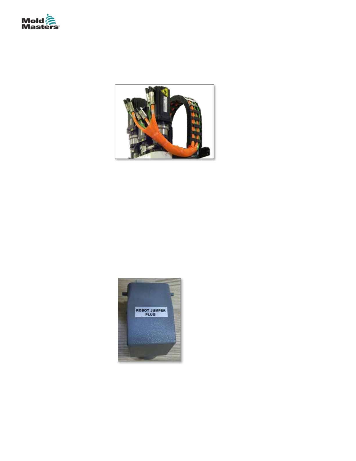
INSTALLATION
5.2 Connect the Controller to the E-Multi
There are 3 sets of cables that connect the controller to the E-Multi:
1. servo power cables
2. servo feedback cables
3. heater - I/O - IMM cables
Figure 5-1 EM3 servo cable routing
The correct sequence must be followed when installing the cables. The
servo power and feedback cables need to be routed through the cable track
before being connected to the motors. The heater and the I/O cables can
be connected directly and are not routed through the cable track. All cables
should be routed so they do not interfere with the mold or molding machine
operation.
5-2
5.3 Connect a Robot to the Controller
E-Multi units are compatible with both E67 and SPI robots. In all cases, the
controller is shipped with a robot jumper plug.
If no robot is used, connect the robot jumper plug to the ROBOT E67
connector on the controller.
Figure 5-2 Robot jumper plug
If an E67 robot is to be used, connect the robot’s E67 cable to the ROBOT
E67 connector on the controller. If an SPI robot is to be used, attach the
optional ROBOT SPI ADAPTER to the ROBOT E67 connector on the
controller, and connect the robot’s SPI cable into the ROBOT SPI ADAPTER.
E-Multi Controller User Manual
© 2020 Mold-Masters (2007) Limited. All Rights Reserved.
Page 49
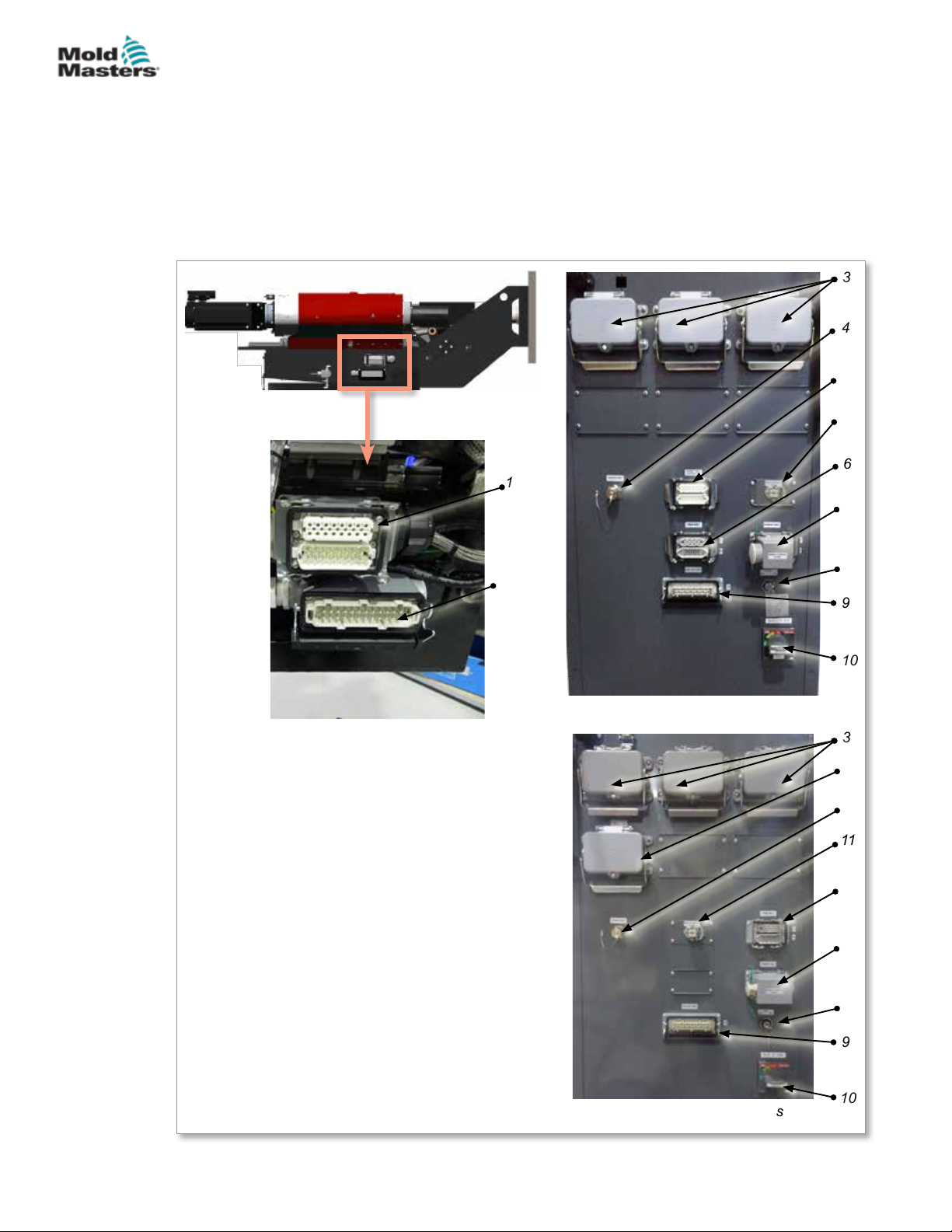
INSTALLATION
5.4 Connect the Controller to the Molding
Machine
E-Multi units are compatible with both E67 and SPI injection machines.
All units ship with an IMM E67 cable. The cable connects to the IMM E67
connection on the controller. If used with an E67 IMM, the cable plugs into the
IMM’s E67 connection directly. If an SPI IMM is used, the cable plugs into the
optional IMM SPI adapter, which then plugs into the IMM SPI connection.
3
4
5
11
6
1
7
5-3
2
E-Multi side connections
1. E-Multi end barrel heat connection
2. E-Multi end aux. inj. I/O connection
3. Zone connections for hot runner control option
4. Remote HMI connection
5. Barrel heater and thermocouple connection
6. IMM E67 connection
7. E67 connection to robot. Jumper plug installed.
8. Bypass switch
9. Auxiliary injection unit connection
10. Main On / O power switch (circuit breaker)
11. Heat exchanger power
8
9
10
EM1/2/3 Controller side connections
3
5
4
11
6
7
8
9
Figure 5-3 E-Multi connection locations
© 2020 Mold-Masters (2007) Limited. All Rights Reserved.
EM4 Controller side connections
10
E-Multi Controller User Manual
Page 50
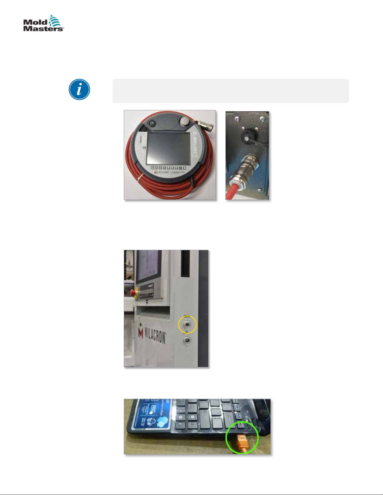
INSTALLATION
5.5 Connect a Handheld HMI (Optional)
E-Multi units are available with optional handheld Human Machine Interface
(HMI) units to allow control of the E-Multi when access to the controller is
inconvenient. The handheld HMI connects to the HAND-HELD HMI connector
on the controller.
IMPORTANT
If a handheld HMI is not connected then a jumper plug is required.
5-4
Figure 5-4 Handheld HMI and connection
5.6 Connect Diagnostic Computer (Optional)
1. Connect one end of the crossover cable to Ethernet port on the controller.
The Ethernet cable can be connected with the power on.
2. Connect the other end of the crossover cable to the Ethernet port on the
diagnostic computer. Note that the diagnostic computer may dier from
the one shown.
E-Multi Controller User Manual
© 2020 Mold-Masters (2007) Limited. All Rights Reserved.
Page 51
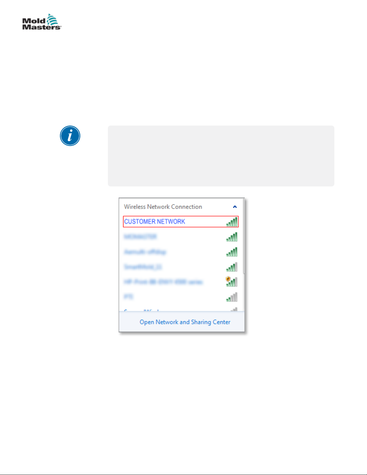
INSTALLATION
Connect Diagnostic Computer (Optional) - continued
3. Connect the diagnostic computer power supply and connect to mains
power. Use the included adapter for 220 V mains.
4. Power up the diagnostic computer and log in with the following
credentials:
User name: emulti
Password: nopassword
5. Connect the diagnostic computer to a WIFI network with internet access.
To see a list of available networks, click the wireless network icon next to
the clock on the taskbar.
NOTE
The diagnostic computer must be connected to the internet using its
wireless network adapter. The wired connection must be used to connect
to the controller. Mold-Masters does not support alternate network
congurations. Connection problems when using alternate congurations
are not covered under warranty and may result in increased support times
and additional costs.
5-5
Figure 5-5 Wireless network icon
6. Open a browser and perform a search to verify internet connectivity.
© 2020 Mold-Masters (2007) Limited. All Rights Reserved.
E-Multi Controller User Manual
Page 52
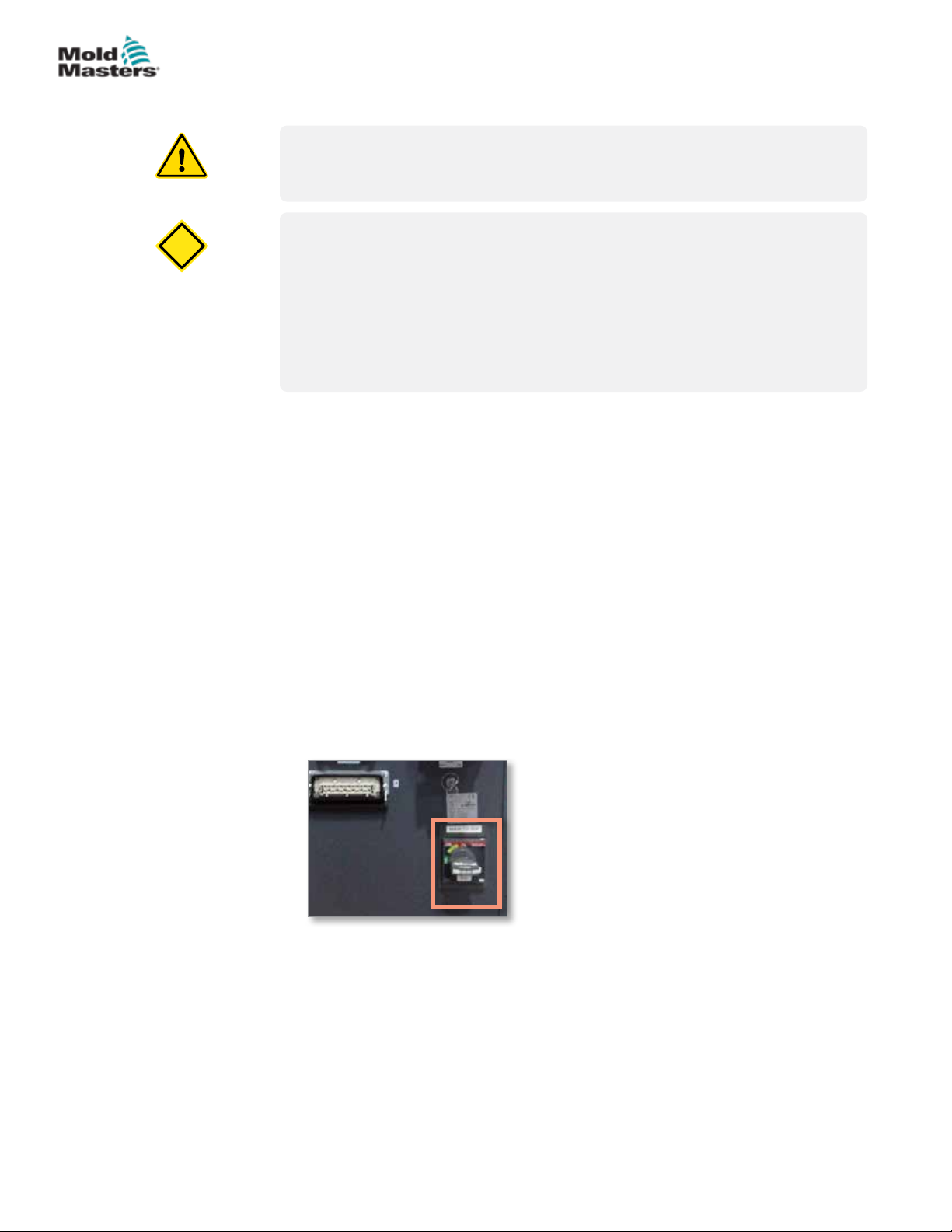
CAUTION
OPERATION
Section 6 - Operation
WARNING
Ensure that you have fully read “Section 3 - Safety” before operating your
E-Multi controller.
CAUTION
Although the main switch has the capacity to switch the whole system o, it
is recommended that this is only done in an emergency.
The controller uses computer technology and should be switched o in
stages.
A sequenced method for switching on and o protects the console and
keeps the switched load to a minimum to extend the life of the main isolator.
6.1 Introduction
Before the E-Multi can be used, the controller will need to be set up.
Please see Section 9 for details on setting parameters such as:
6-1
• Heating
• Control
• Injection speeds
• Trigger signals, etc.
6.2 Isolate the Controller
For all E-Multi controllers, the main power switch is a rotary circuit breaker
at the rear of the cabinet. This switch is rated to safely handle the total load
current during switch on and switch o.
You can use a suitably-sized padlock, or similar device to lock the switch in
the o position to lockout electrical supply during maintenance.
Figure 6-1 E-Multi main power switch
© 2020 Mold-Masters (2007) Limited. All Rights Reserved.
E-Multi Controller User Manual
Page 53
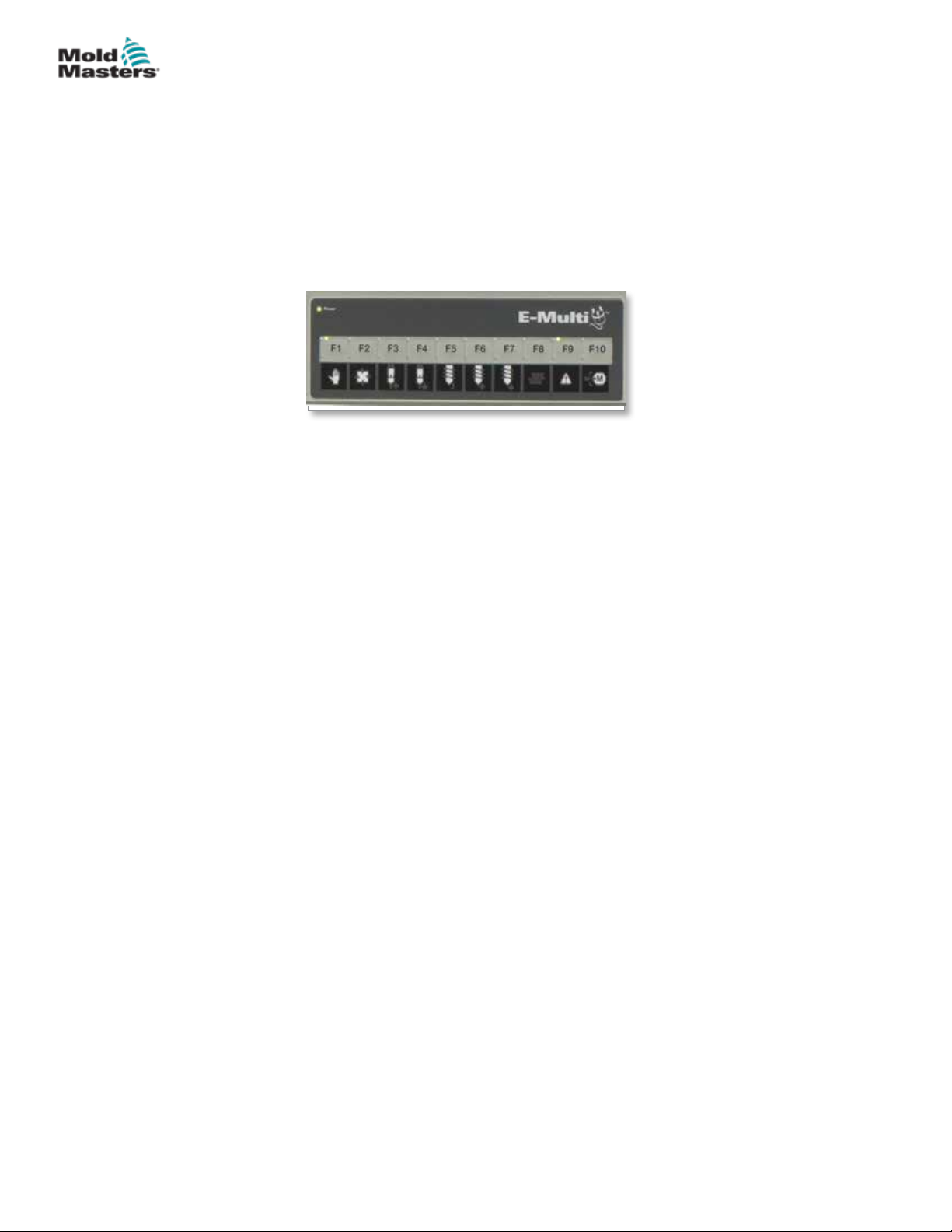
OPERATION
6.3 Switch On
When the main power switch is turned to on, the servo motors will not be
enabled.
Once the software has nished loading and the display shows the Overview
page, the system is in Manual mode and is ready to have the heaters
switched on to bring the barrel heaters to temperature.
Servo motors may be enabled by pressing the [F10] button on the button strip
located below the display. Once the servo motors are enabled, the LED at the
top left of the button will turn on.
Figure 6-2 Button strip below controller display (HMI)
The E-Multi controller can be used in Manual, Setup and Auto/Ready mode.
6.4 Switch Off (Shutdown)
6-2
Mold-Masters recommends that you use the console to shutdown the heating
load, and only use the main current breaker switch to turn o the dormant
controller.
6.4.1 Shutdown the Heating
Press the [F8] button located on the button strip located below the display.
The LED at the top left of the [F8] button indicates heating status.
• If the LED is lit, heating is active.
• If the LED is not lit, heating is o.
6.4.2 Shutdown the Controller
Once heating has been turned o, the system may be turned o using the
main switch on the back of the controller.
E-Multi Controller User Manual
© 2020 Mold-Masters (2007) Limited. All Rights Reserved.
Page 54

CAUTION
E-MULTI CONTROLLER HMI INTERFACE
Section 7 - E-Multi Controller
HMI Interface
WARNING
Ensure that you have fully read “Section 3 - Safety” before operating your
E-Multi controller.
7.1 Introduction
CAUTION
Values on the screen pictures in this manual may not reect the correct
values for your machine. Do not change settings based on the screen
pictures.
This part of the manual describes the touchscreen interface or Human
Machine Interface (HMI) and shows what functions and information are
available.
From the various screens you will be able to:
7-1
• Set individual nozzle temperatures. Set high and low temperature limits
for closed loop zone control.
• Congure and calibrate nozzle position and contact force.
• Create mold specic setups (recipes). These can be stored and called up
when molds are changed.
• Congure the injection sequence and monitor it.
• Congure the hold sequence and monitor it.
• Congure the plasticize sequence and monitor it.
• Use the software oscilloscope (SWO) functionality to monitor operation.
• Control the password protection on all settings.
• Print out any displays or data listings.
• Connect and monitor Euromap connection between the E-Multi, molding
machine and robot.
© 2020 Mold-Masters (2007) Limited. All Rights Reserved.
E-Multi Controller User Manual
Page 55
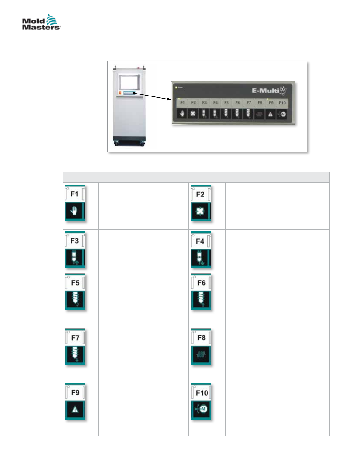
E-MULTI CONTROLLER HMI INTERFACE
7.2 Cabinet Mounted Control Buttons
The cabinet mounted buttons are provided for quick access to commonly
used functions.
Figure 7-1 Cabinet mounted control buttons
Table 7-1 Control Buttons
F1 Manual/Setup Mode
E-Multi will not be controlled
by the molding machine in this
mode. This mode is used for
setup functions and jogging
motors.
F2 Ready / Auto Mode
E-Multi will be triggered by the
molding machine depending on the
E-Multi triggering method selected.
7-2
F3 Carriage Move Retract
The carriage can be retracted
by placing the E-Multi in Manual
/ Setup mode and pressing this
button.
F5 Screw Rotate
The screw can be rotated by
placing the E-Multi in Manual /
Setup mode and pressing this
button. The screw will rotate
until you press this button again
to turn it o.
F7 Screw Advance
The screw can be advanced by
placing the E-Multi in Manual /
Setup mode and pressing this
button.
F9 Acknowledge/Reset
current alarms
Any current alarms will be
acknowledged and a reset will
be attempted when this button is
pressed.
F4 Carriage Move Advance
The carriage can be advanced by
placing the E-Multi in Manual / Setup
mode and pressing this button.
F6 Screw Retract
The screw can be retracted by
placing the E-Multi in Manual / Setup
mode and pressing this button.
F8 Nozzle Heaters
The nozzle heaters can be turned
o / on at any time with this button.
Note: If the heater temperature is
outside the preset limits, the E-Multi
will not operate and an error will be
displayed.
F10 Enable Servo Motors
The injection and screw servo axis
motor control is enabled by pressing
this button. The LED on the top left
corner of this button will light up when
the drives are enabled. No motion will
occur if this button is not lit up.
E-Multi Controller User Manual
© 2020 Mold-Masters (2007) Limited. All Rights Reserved.
Page 56
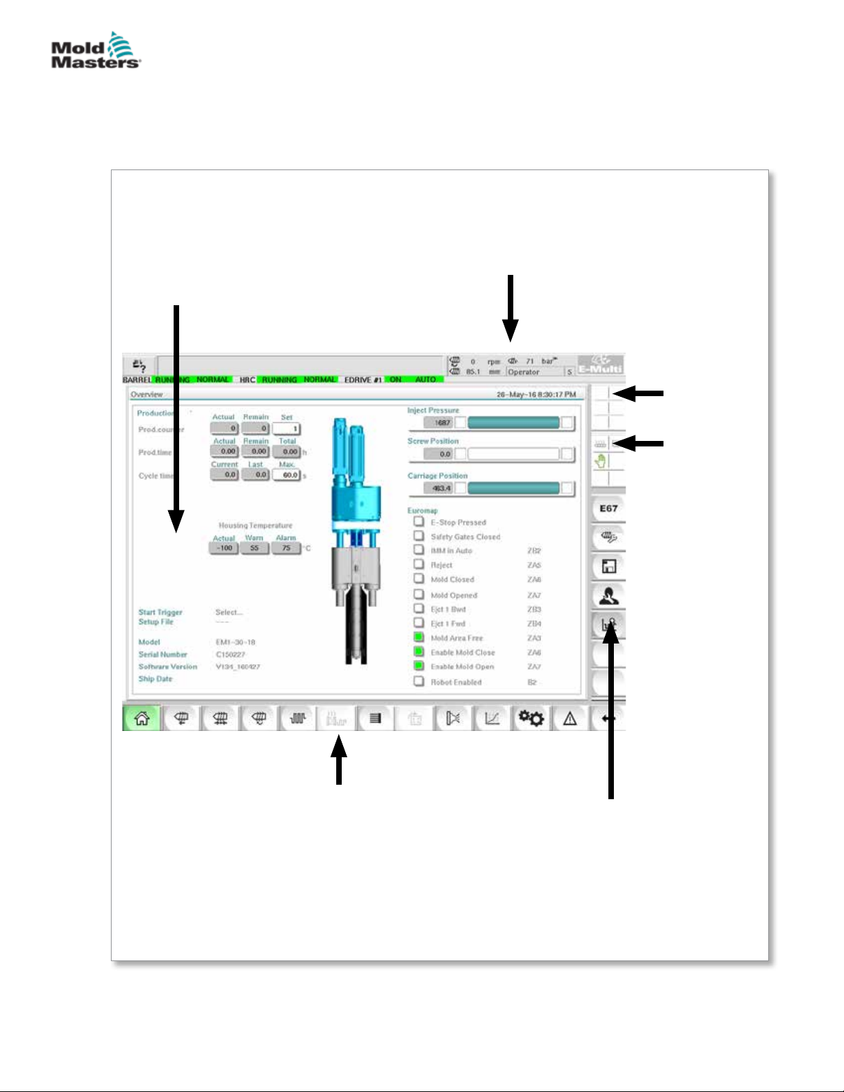
E-MULTI CONTROLLER HMI INTERFACE
7.3 E-Multi Touchscreen Interface
The E-Multi is a complex controller but the main screen is organized to
simplify navigation and to show those parameters which are most useful to
monitor. The main parts of the screen are shown here below.
7-3
Main Screen
The main screen area may display
information, have elds for entering or
displaying information and have touch
sensitive areas to select or deselect
options.
Top Bar - Status Display
This area displays current live status
for screw position, screw revolution and
injection pressure. It also displays the
current user and user level.
Active
Movement
Icons
Status
Icons
Heater on / o,
Motor on / o,
etc.
Bottom Bar - Screen Navigation
Buttons
The bottom bar navigates to the main HMI
screens: Overview, Valve Gate Settings, Injection
Settings, Hold Settings, Recovery Settings, etc.
© 2020 Mold-Masters (2007) Limited. All Rights Reserved.
Right Bar - Context Menu
Buttons
This bar displays system information
at the top and touch buttons below
that give quick access to commonly
used functions. Some buttons will
be screen specic.
E-Multi Controller User Manual
Page 57
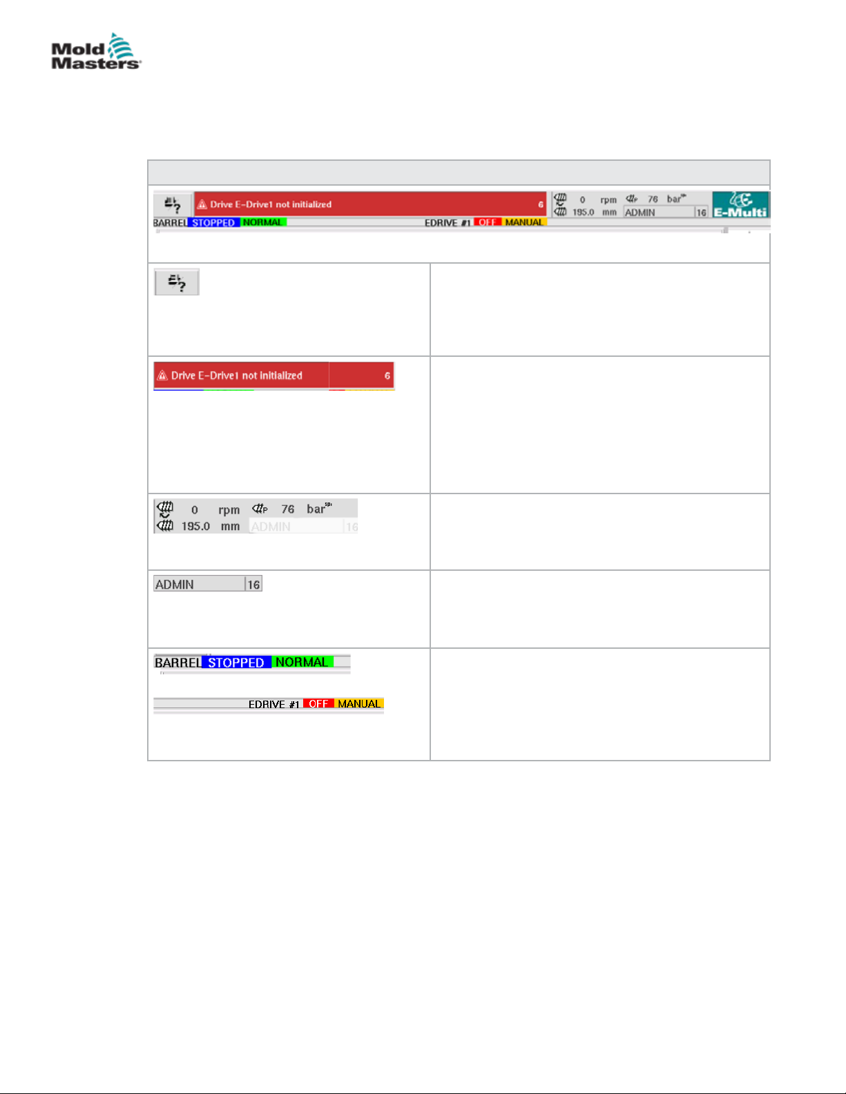
E-MULTI CONTROLLER HMI INTERFACE
7.3.1 Top Bar - Status Display
The status display is located at the top of the screen and is always shown.
The status display has 5 boxes of information:
Table 7-2 Top Bar - Status Display
Print Command
Useful to obtain a screen picture or printed record
of production information and settings, or for
communicating with service people.
Warning / Error Status Messages
If an alarm occurs, this box shows red with a
description of the alarm.
If two or more alarms occur, they are counted at
the right hand side. Six alarms are shown in this
example.
To see all active alarms tap the red message bar or
the [Alarm] button.
Current Live Status
Live status on screw speed and position and injection
pressure.
7-4
User Level
Shows current user and current user access level.
Mode and Status Window
Shows what systems are active, their status and if
any alarms are present.
E-Multi Controller User Manual
© 2020 Mold-Masters (2007) Limited. All Rights Reserved.
Page 58
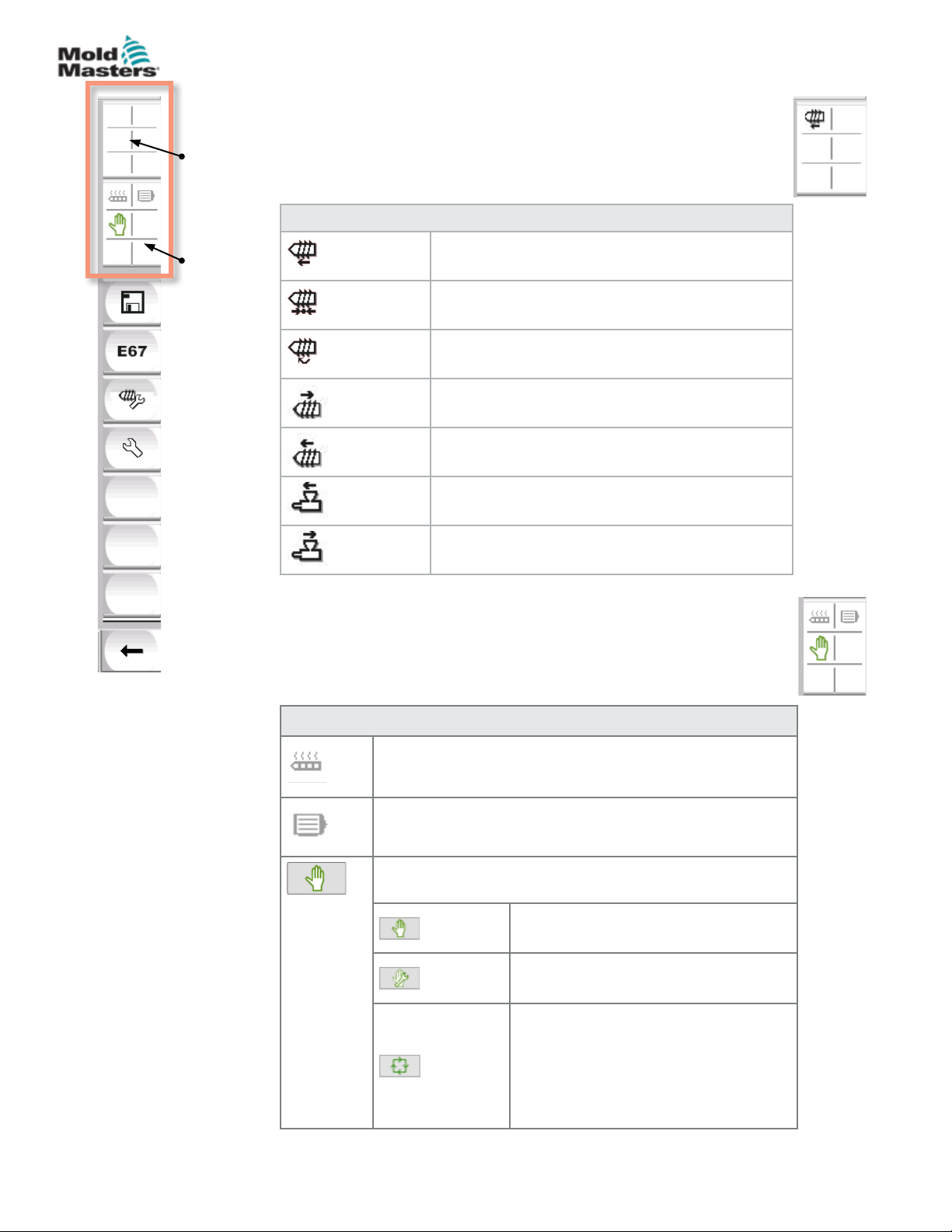
Active
movement
icons
E-MULTI CONTROLLER HMI INTERFACE
7.3.2 Active Movement Icons
These icons are displayed above the side bar while the E-Multi
is running. These icons give the user valuable information on the
current status of the E-Multi. If the icon is green, it is active. If the
icon is greyed out, it is inactive.
Table 7-3 Active Movement Icons
7-5
Status
icons
Screw injecting
Screw holding
Screw rotating (plasticizing)
Screw moving backward
Screw moving forward
Carriage moving forward
Carriage moving backward
7.3.3 Status Icons
These icons display the current machine operation status.
Table 7-4 Status Icons
Barrel Heat Status - grey (shown) when barrel heaters are
o and green when barrel heaters are on. Same as [F8]
button LED.
Servo Motor Active - grey (shown) when servo motors are
o and green if on
Mode Indicator - An icon indicating the current machine
mode
Manual Mode. Machine jogs at full
speed.
Set up Mode. Machine jogs at set up
speed.
Automatic Mode. Machine will operate
automatically when the molding
machine provides the proper trigger
and the EuroMap connections from the
molding machine and robot are correct.
© 2020 Mold-Masters (2007) Limited. All Rights Reserved.
E-Multi Controller User Manual
Page 59
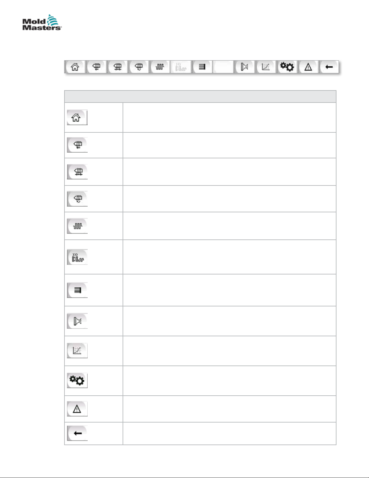
E-MULTI CONTROLLER HMI INTERFACE
7.3.4 Bottom Bar - Screen Navigation Buttons
The Screen Navigation buttons at the bottom of the screen are used to
navigate to the main HMI screens.
Table 7-5 Screen Navigation Buttons
Overview (Home) Screen
This screen is the 'home page' for the system. It provides an overview of the
operation of the E-Multi.
Injection Settings Screen
This screen is used to adjust settings for the injection phase of the E-Multi
injection molding cycle.
Hold Settings Screen
This screen is used to adjust the settings for the hold phase of the E-Multi
injection molding cycle.
Recovery Settings Screen
This screen is used to adjust the settings for the recovery or plasticize phase
of the E-Multi injection cycle.
7-6
Barrel Temperature Settings Screen
This screen is used to adjust the settings for the E-Multi barrel heaters.
Hot Runner Temperature Control Screen
This screen is used to adjust parameters for hot runner temperature control,
for systems with this integrated option. If the option is not available then the
button will be greyed out as shown above.
E-Drive Screen
This screen is used to adjust E-Drive parameters, for systems with an
integrated E-Drive. If the option is not available then the button will be greyed
out.
Valve Gate Screen
This screen is used to adjust the behavior of the digital valve gate trigger
outputs.
Production Graph Screen
The Production Graph screen is used to display real time production
information based on preset system variables.
Machine Specication (Service Overview) Screen
This screen serves as a central access point for all conguration screens as
well as service and maintenance screens.
E-Multi Controller User Manual
Alarm Display
Takes the user to the alarm screen which displays a list of alarms triggered by
the control system.
Back Button
Returns to the screen that was previously displayed.
© 2020 Mold-Masters (2007) Limited. All Rights Reserved.
Page 60
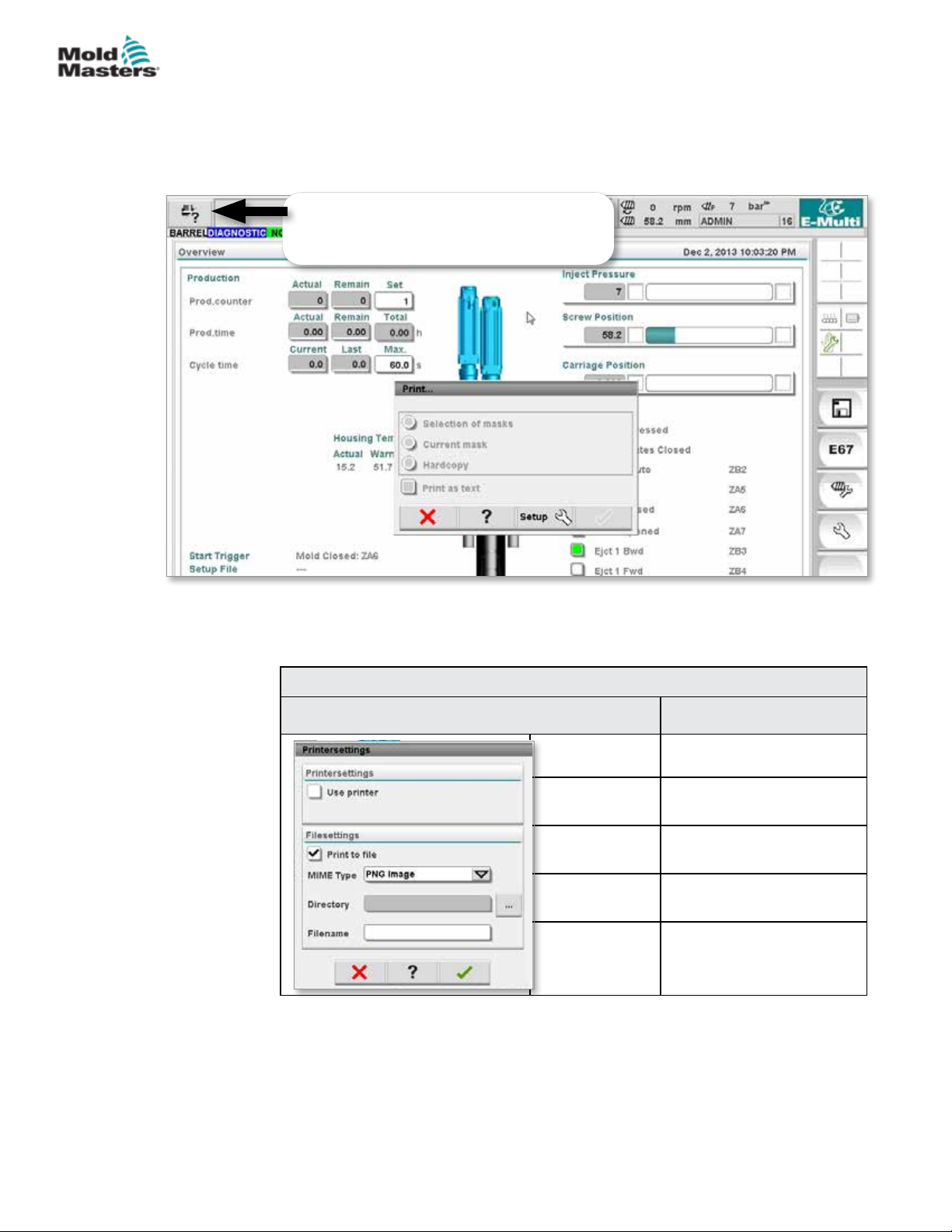
E-MULTI CONTROLLER HMI INTERFACE
7.3.5 Print Functionality
Before moving into the screen descriptions it is useful to know how to capture
or print screens. This is often used by production personnel to obtain a
printed record of production information and settings or for communicating
with service people.
To open the print dialog, tap the print button
on the top left of the screen.
7-7
Figure 7-2 Print functionality screen
When the Print Setup button is tapped, the printer setup dialog will appear.
The printer settings are described below.
Screen Element Description
Table 7-6 Printer Settings
Use Printer Output to a USB printer.
Print to File Output to a le.
MIME Type Selection of a MIME-type
for the output le.
Directory Target directory for the
output le.
Filename File name of the output le.
© 2020 Mold-Masters (2007) Limited. All Rights Reserved.
E-Multi Controller User Manual
Page 61

E-MULTI CONTROLLER HMI INTERFACE
7.4 Screen Descriptions
In this user manual, screen descriptions are presented in the order of the
lower screen navigation buttons. Some screens required a description of
many subsidiary screens which are indicated with an arrow (→) under the
parent screen. Many screens can also be accessed using the context buttons
on the right of a screen.
Overview (Home) Screen
Injection Settings Screen
Hold Settings Screen
Recovery Settings Screen
Barrel Temperature Settings Screen
Hot Runner Temperature Control Screen (Option)
→ Monitor Screen
→ Setup Screen (Supervisor Level)
→ Utilities Screen (Supervisor Level)
E-Drive Screen (Option)
→ Overview Screen
→ Settings Screen (Supervisor Level)
7-8
Valve Gate Screen
Production Graph Screen
→ Setup → Conguration Details
Process Data (PD) Protocol Screen
Main Screen
→ System Settings
→ Carriage
→ Info-Log
→ Production Graph
→ Programmable I/O
→ I/O Monitor
→ Production Settings
→ Drive Manager
→ Task Monitor
→ Prole Settings
→ Drive Parameter Monitor
→ PID Settings
→ Machine Data
→ Variable Monitor
→ Delay Settings
→ Calibration Settings
E-Multi Controller User Manual
Alarm Display
Mold Data Screen
Euromap 67 Screen
© 2020 Mold-Masters (2007) Limited. All Rights Reserved.
Page 62
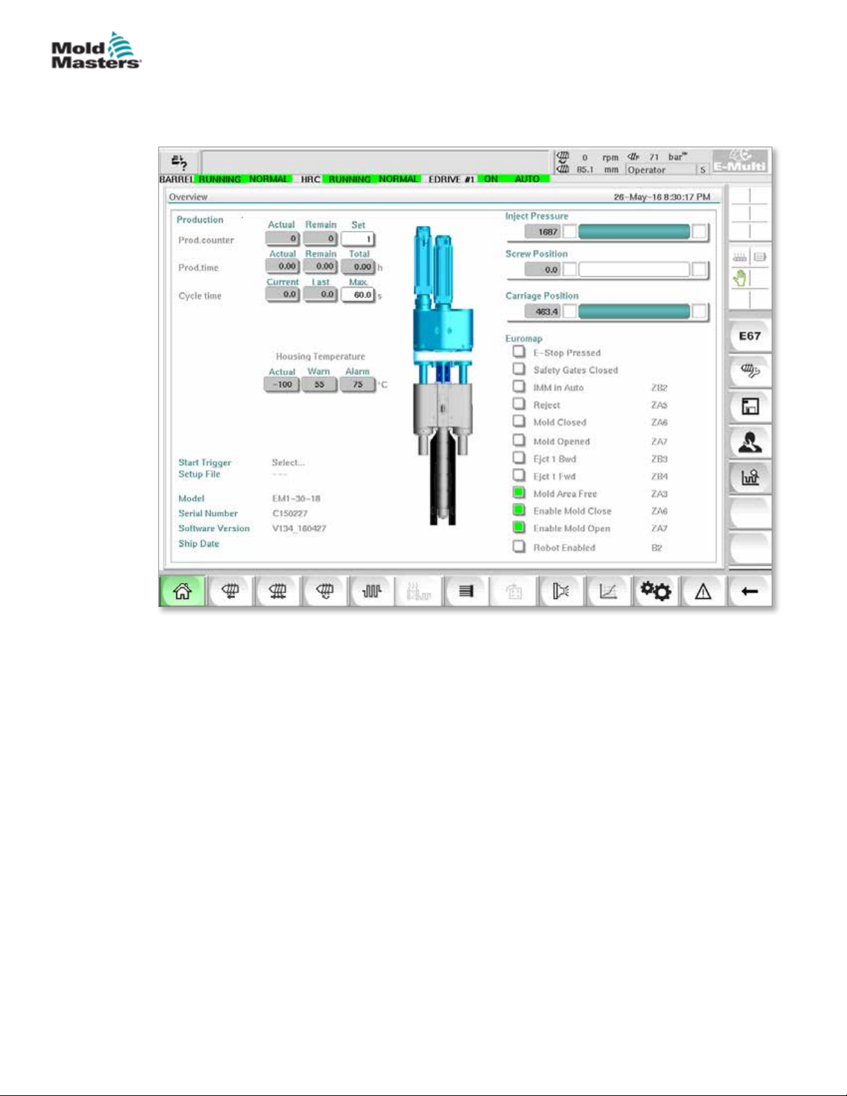
E-MULTI CONTROLLER HMI INTERFACE
7.5 Overview Screen
This screen serves as a standard display in ongoing production operation and
provides operating personnel with an overview of the machine’s key data.
7-9
Figure 7-3 Overview screen
© 2020 Mold-Masters (2007) Limited. All Rights Reserved.
E-Multi Controller User Manual
Page 63
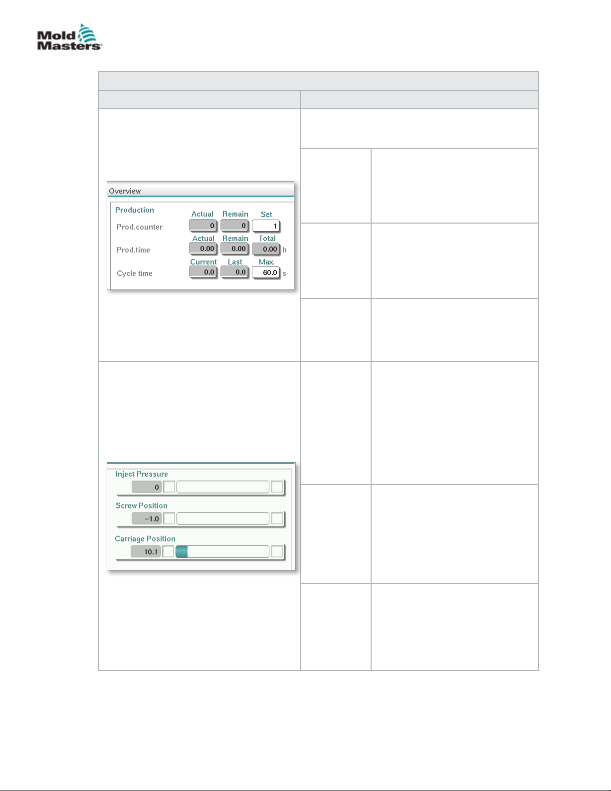
E-MULTI CONTROLLER HMI INTERFACE
Overview Screen - continued
Table 7-7 Overview Screen Components
Screen Components Description
Live E-Multi Production Values at the top of the
screen provides the operating personnel with an
overview of production data:
Prod.
counter
Prod. time The current production time is
Cycle time The current cycle time is shown in
Injection
Pressure
Screw
Position
Carriage
Position
7-10
The current number of shots (shot
counter) is shown in the Actual eld.
The remaining number of shots is
shown in the Remain eld. The total
number of shots to be produced can
be specied in the Set eld.
shown in the Actual eld. The
remaining production time is shown
in the Remain eld. The total
production time is shown in the
Total eld.
the left eld (grey). The last cycle
time is shown in the middle eld
(grey). The maximum cycle time is
shown in the right eld (white).
When machine is idle, this shows
the system preload pressure.
When an injection cycle is active,
this shows the plastic pressure
generated by the injection unit.
An analog bar shows the current
position graphically. Markers to
the left and right of the analog bar
indicate when the end position is
reached.
Current position of the E-Multi
screw, relative to the fully forward
reference position.
An analog bar shows the current
position graphically. Markers to
the left and right of the analog bar
indicate when the end position is
reached.
The position of the carriage relative
to the nozzle touch point (fully
forward). An analog bar shows the
current position graphically. Markers
to the left and right of the analog
bar indicate when the end position
is reached.
E-Multi Controller User Manual
© 2020 Mold-Masters (2007) Limited. All Rights Reserved.
Page 64
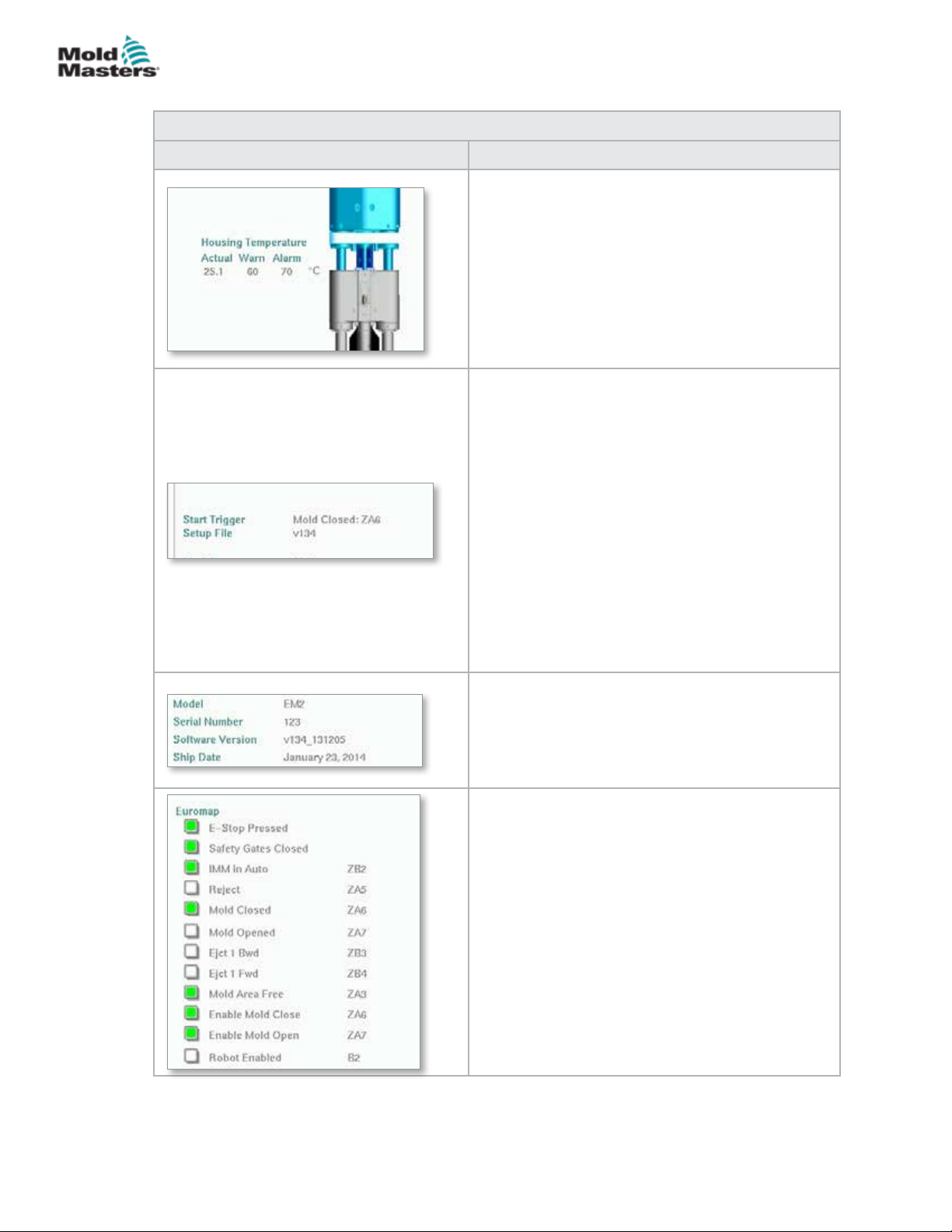
E-MULTI CONTROLLER HMI INTERFACE
Overview Screen - continued
Table 7-7 Overview Screen Components
Screen Components Description
Live E-Multi Barrel Housing Temperature
This section displays the actual and set point values
for the Housing Temperature. The housing color
will change to orange if the warning temperature
is exceeded and red if the alarm temperature is
exceeded.
Sequence Start / Trigger
This section displays the current start trigger
settings. The settings may be changed on the
Euromap 67 screen.
Trigger: This is the Euromap I/O signal from the
molding machine that starts the E-Multi process.
Start Delay Time: When the Euromap signal
is detected, this time delay is added before the
E-Multi process starts. Set to zero to disable.
Start Delay Count: At the start of the mold run
only, the chosen number of injection molding
machine cycles will automatically run before the
E-Multi injection process starts.
7-11
Setup File
Shows the current software version.
System Information
This section displays information specic to the
E-Multi system. When requesting service, provide
this information to the Mold-Masters representative.
Euromap
This screen area provides a quick overview of the
live status of the Euromap signals. The box is either
green if the input or output is on, or white (empty) if
the input or output is o.
Green - signal is logical true
Empty - signal is logical false
© 2020 Mold-Masters (2007) Limited. All Rights Reserved.
E-Multi Controller User Manual
Page 65
E-MULTI CONTROLLER HMI INTERFACE
Overview Screen - continued
Table 7-8 Overview Screen Context Menu Buttons
Mold Data
Navigates to the Mold Settings Screen where mold
data may be saved and loaded for each specic
mold. See “Mold Data Screen” on page 7-88
Euromap 67
Navigates to the EuroMap 67 screen which allows the
user to monitor communications between the E-Multi
and the injection molding machine. See “Euromap
E67 Screen” on page 7-90.
Reference Settings
Navigates to the Reference Settings screen where
carriage reference position, screw reference position
and injection pressure reference may be set or reset.
System Settings
Navigates to the System Settings Screen where
screen saver options and global settings like
language, date and time, units can be adjusted. This
screen also displays system information like current
user, software version, and IP addresses.
See “System Settings Screen” on page 7-61.
7-12
E-Multi Controller User Manual
© 2020 Mold-Masters (2007) Limited. All Rights Reserved.
Page 66
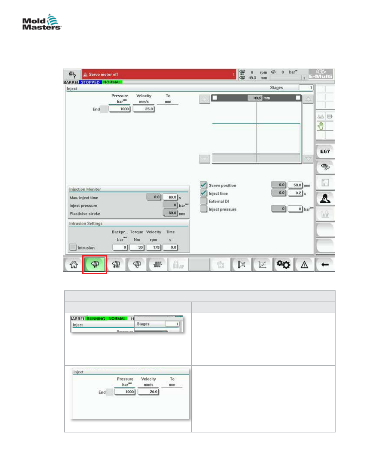
E-MULTI CONTROLLER HMI INTERFACE
7.6 Injection Settings Screen
This screen is used to adjust screw movement settings during injection. It is
also used to adjust the transition point, at which the system changes from
injection to hold pressure.
7-13
Figure 7-4 Injection settings screen
Table 7-9 Injection Settings Screen Components
Screen Components Description
Inject
This section displays the current injection prole.
The prole is displayed numerically in the elds on
the left and graphically on the right.
The number of injection steps may be adjusted
using the stages eld at the top left. A maximum of
10 steps may be selected.
Pressure and Velocity Input Fields
These settings can be adjusted by entering values
directly into these elds.
These elds are used for setting the Pressure and
Velocity between the end position of the previous
stage (in case of stage 1, the end position of the
previous part movement) and the position specied
under the 'To' column. The last step will complete
when one of the transition conditions is met.
© 2020 Mold-Masters (2007) Limited. All Rights Reserved.
E-Multi Controller User Manual
Page 67
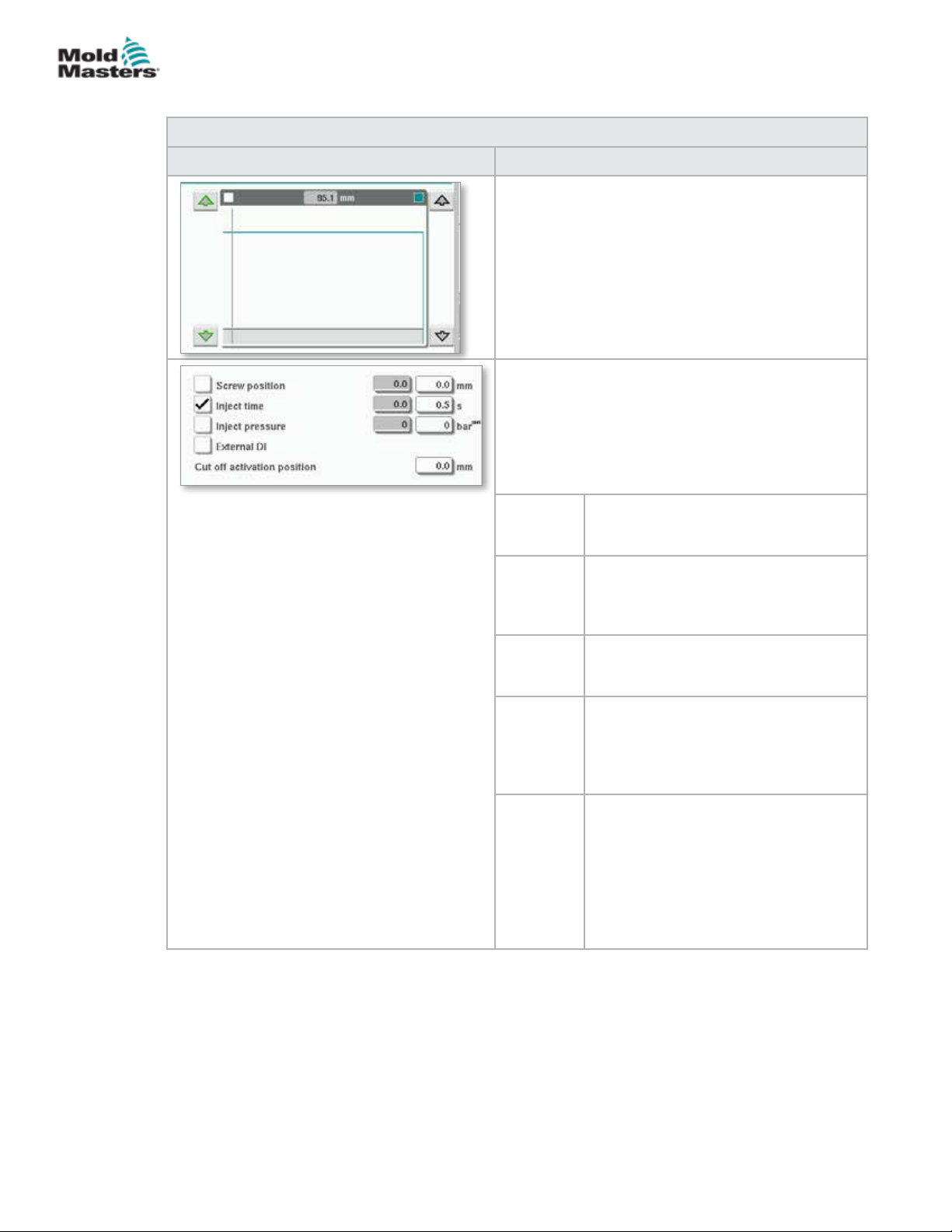
E-MULTI CONTROLLER HMI INTERFACE
Injection Settings Screen - continued
Table 7-9 Injection Settings Screen Components
Screen Components Description
Pressure and Velocity Input Graph
Alternatively, the Pressure (teal) and the Velocity
(grey) values are shown in the form of prole graphs
and the values can be adjusted using the arrow
keys next to the prole graphs.
On each tap of the arrow, the prole graph is
adjusted by +/-5 bar and/or +/-5%.
Transition Conditions
Used to set the conditions when the system
changes from injection to the hold.
If multiple conditions are selected, the change will
occur when the rst condition is met.
Activate conditions by checking the box to the left of
the eld label.
Screw
position
7-14
Species the screw position at which
the system changes to hold pressure.
Inject time Species the number of seconds after
which the system changes to hold
pressure (measured from the start of
the injection process).
Inject
pressure
External DIThe cut o position is signaled by an
Cut O
Activation
Position
Species the injection pressure at
which the system changes to hold
pressure.
external digital input. The digital input
is shown on the electrical schematics
and is labeled:
Hold Transition (External).
Injection pressure for transition will not
be monitored until the screw position
is less than this position. It is used
to prevent transition when injection
pressure spikes at the start of injection.
Note: This eld is only available when
transition on injection pressure is
selected.
E-Multi Controller User Manual
© 2020 Mold-Masters (2007) Limited. All Rights Reserved.
Page 68
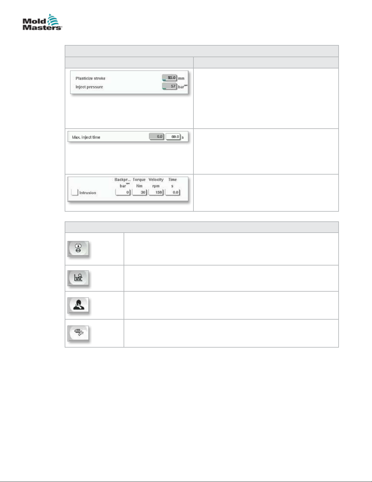
E-MULTI CONTROLLER HMI INTERFACE
Injection Settings Screen - continued
Table 7-9 Injection Settings Screen Components
Screen Components Description
Inject pressure:
Displays the current Injection pressure.
Plasticize stroke:
Displays the current plasticize stroke.
The plasticize stroke is the value of the last
plasticizing stage plus the position value of
'Decompression after plasticize' in the plasticizing
screen.
Max. inject time:
The left eld displays the inject time of the current
cycle. In the right eld, the maximum inject time
(without delay time) can be set.
If this time is exceeded an alarm will be raised and
the cycle will be stopped.
Intrusion:
The elds to the right will be used for setting
Pressure, Velocity and Time for the intrusion (screw
rotation before Inject).
7-15
Table 7-10 Injection Settings Screen Context Menu Buttons
Motor or Drive Information Screen
Production Graph - Congurable View
Production Settings
Reference Settings
© 2020 Mold-Masters (2007) Limited. All Rights Reserved.
E-Multi Controller User Manual
Page 69
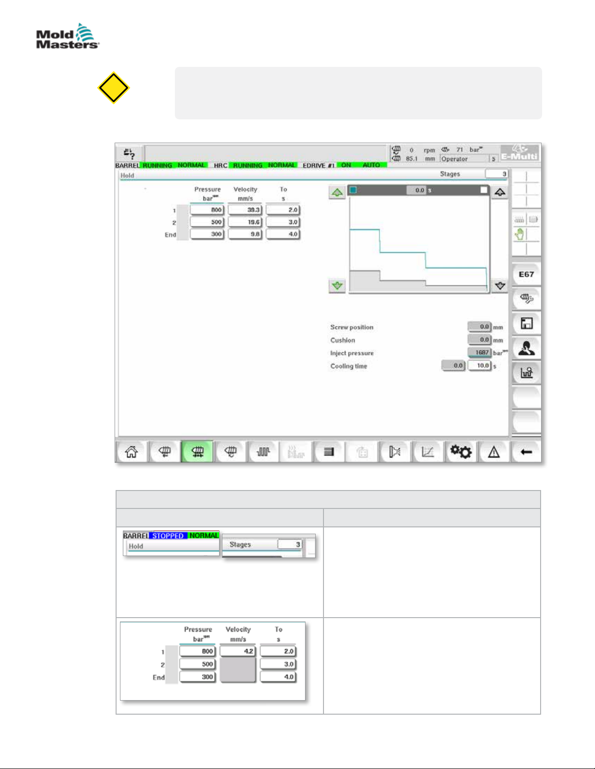
CAUTION
E-MULTI CONTROLLER HMI INTERFACE
7.7 Hold Settings Screen
CAUTION
Recovery back pressure should never be adjusted below the idle (preload)
pressure.
This screen is used for adjusting hold pressure settings.
7-16
Figure 7-5 Hold settings screen
Screen Components Description
E-Multi Controller User Manual
Table 7-11 Hold Setting Screen Components
Hold
This section displays the current hold prole.
The prole is displayed numerically in the elds
on the left and graphically on the right.
The number of hold steps may be adjusted
using the Stages eld at the top left. A maximum
of 10 steps may be selected.
Pressure and Velocity Input Fields
These settings can be adjusted by entering
values directly into these elds.
These elds are used for setting the Pressure
and Velocity between the end position of the
previous stage (in case of stage 1, the end
position of the previous part movement) and the
position specied under the 'To' column.
© 2020 Mold-Masters (2007) Limited. All Rights Reserved.
Page 70
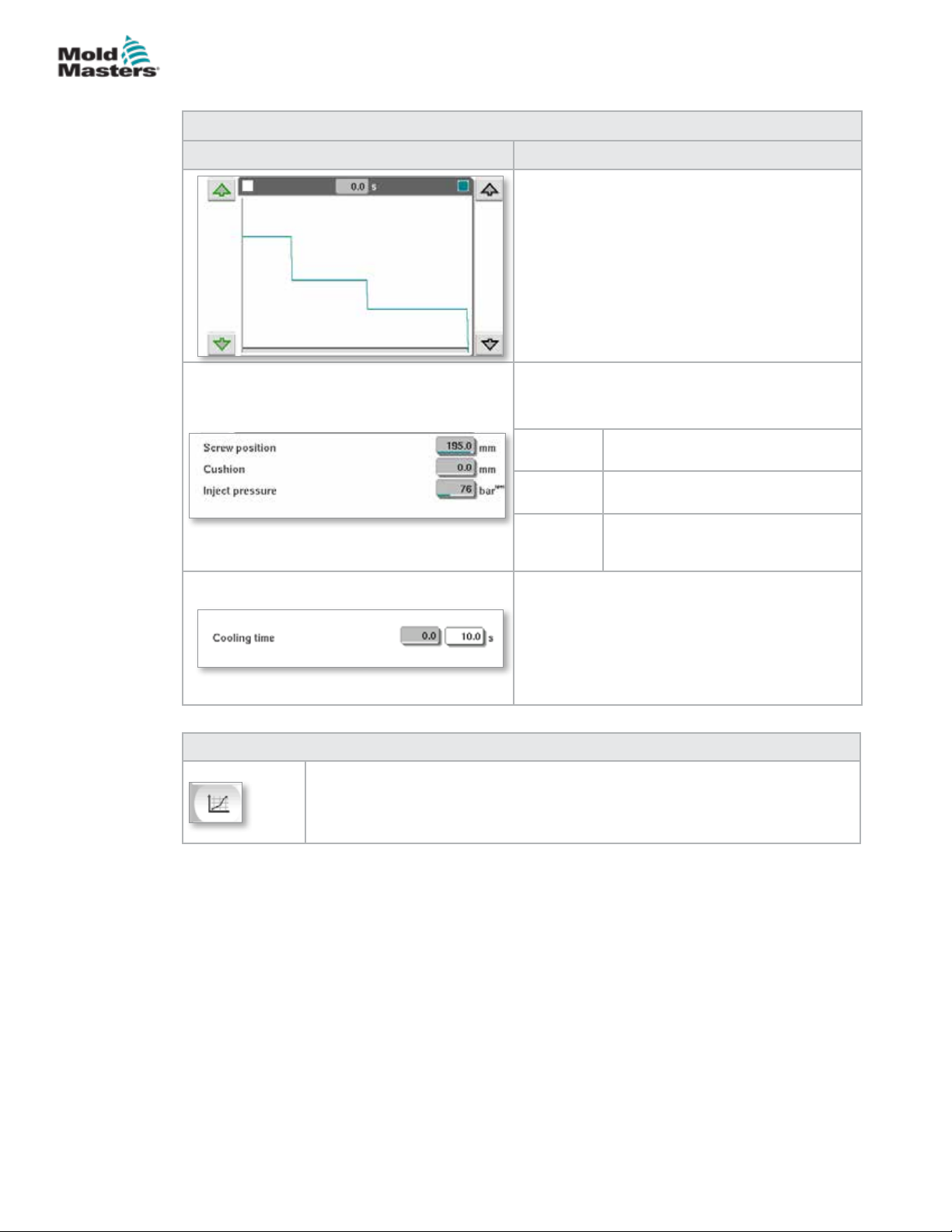
E-MULTI CONTROLLER HMI INTERFACE
Hold Settings Screen - continued
Table 7-11 Hold Setting Screen Components
Screen Components Description
Pressure and Velocity Input Graph
Alternatively, the Pressure (teal) and the Velocity
(grey) values are shown in the form of prole
graphs and the values can be adjusted using the
arrow keys next to the prole graphs.
On each click of the arrow, the prole graph is
adjusted by +/-5 bar and/or +/-5%.
Data Display
This area of the screen displays current
pressure and screw position information.
Screw
position
Cushion Display of melt cushion at the end
Inject
pressure
7-17
Maximum screw forward position at
the end of hold.
of injection.
Displays the current injection
pressure.
Cooling Time
The current cooling time (actual value) is shown
in the left eld (grey). The cooling time (set
point) may be entered into the right (white) eld.
Table 7-12 Hold Settings Screen Context Menu Buttons
Production Graphs
Navigates to the Production Graph screen which provides real time data on the
current production process.
© 2020 Mold-Masters (2007) Limited. All Rights Reserved.
E-Multi Controller User Manual
Page 71
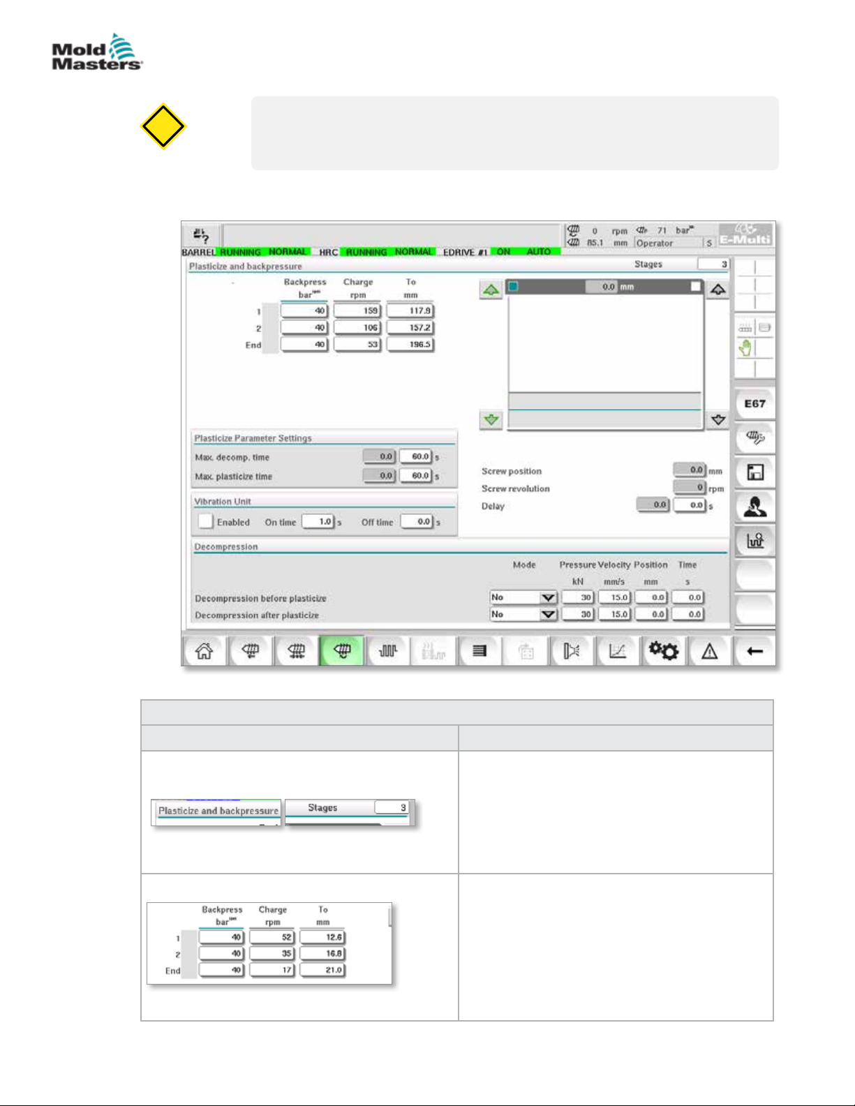
CAUTION
E-MULTI CONTROLLER HMI INTERFACE
7.8 Recovery Settings Screen
CAUTION
Recovery back pressure should never be adjusted below the idle (preload)
pressure.
This screen is used to adjust the settings for backpressure and feed screw
speed during the recovery part of the injection cycle.
7-18
Figure 7-6 Recovery settings screen
Screen Components Description
E-Multi Controller User Manual
Table 7-13 Recovery Settings Screen Components
Plasticize and backpressure
This section displays the current recovery prole.
The prole is displayed numerically in the elds on
the left and graphically on the right.
The number of recovery steps may be adjusted
using the Stages eld at the top left. A maximum of
5 steps may be selected.
Backpressure and Charge Input Fields
These settings can be adjusted by entering values
directly into these elds.
These elds are used for setting the Backpressure
and Charge between the end position of the
previous stage (in case of stage 1, the end
position of the previous part movement) and the
position specied under the 'To' column.
© 2020 Mold-Masters (2007) Limited. All Rights Reserved.
Page 72
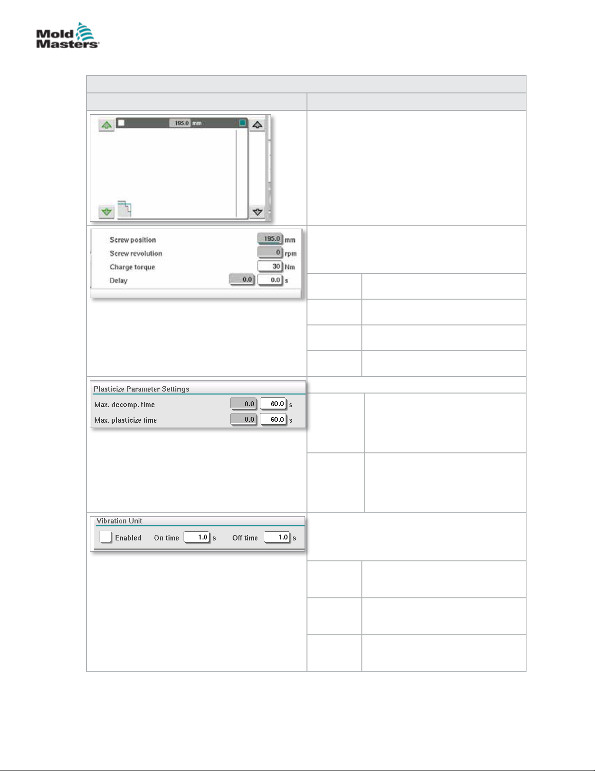
E-MULTI CONTROLLER HMI INTERFACE
Recovery Settings Screen - continued
Table 7-13 Recovery Settings Screen Components
Screen Components Description
Backpressure and Charge Input Graph
Alternatively, the Backpressure (teal) and the
Charge (grey) values are shown in the form of
prole graphs and the values can be adjusted
using the arrow keys next to the prole graphs.
On each click of the arrow, the prole graph is
adjusted by +/-5 bar and/or +/-5%.
Data Display
This area of the screen displays the current inject
pressure and screw revolution and position.
The Delay eld can be adjusted - see below.
Screw
position
Screw
revolution
Charge
torque
Delay The delay time for the start of
Plasticize Parameter Settings
Max.
decomp.
time
Max.
plasticize
time
Vibration Unit
An optional vibrator may be attached to the hopper
or feed tube. Vibration can be used to help the
ow of material into the feed block.
Enabled Checking this box will enable the
On Time Species the amount of time the
O Time Species the amount of time the
Displays the current screw position.
Displays the current screw revolution.
Species the maximum charge
torque.
plasticize is specied here.
Here the maximum allowed
decompression time can be set.
This value is the maximum allowed
value to be input on the plasticize
screen.
Here the maximum allowed
plasticize time can be set.
If the time is exceeded an alarm
will be raised and the cycle will be
stopped.
vibration unit. Unchecking the box will
disable the vibration unit.
vibration is on within the on / o
cycle.
vibration is o within the on / o
cycle.
7-19
© 2020 Mold-Masters (2007) Limited. All Rights Reserved.
E-Multi Controller User Manual
Page 73
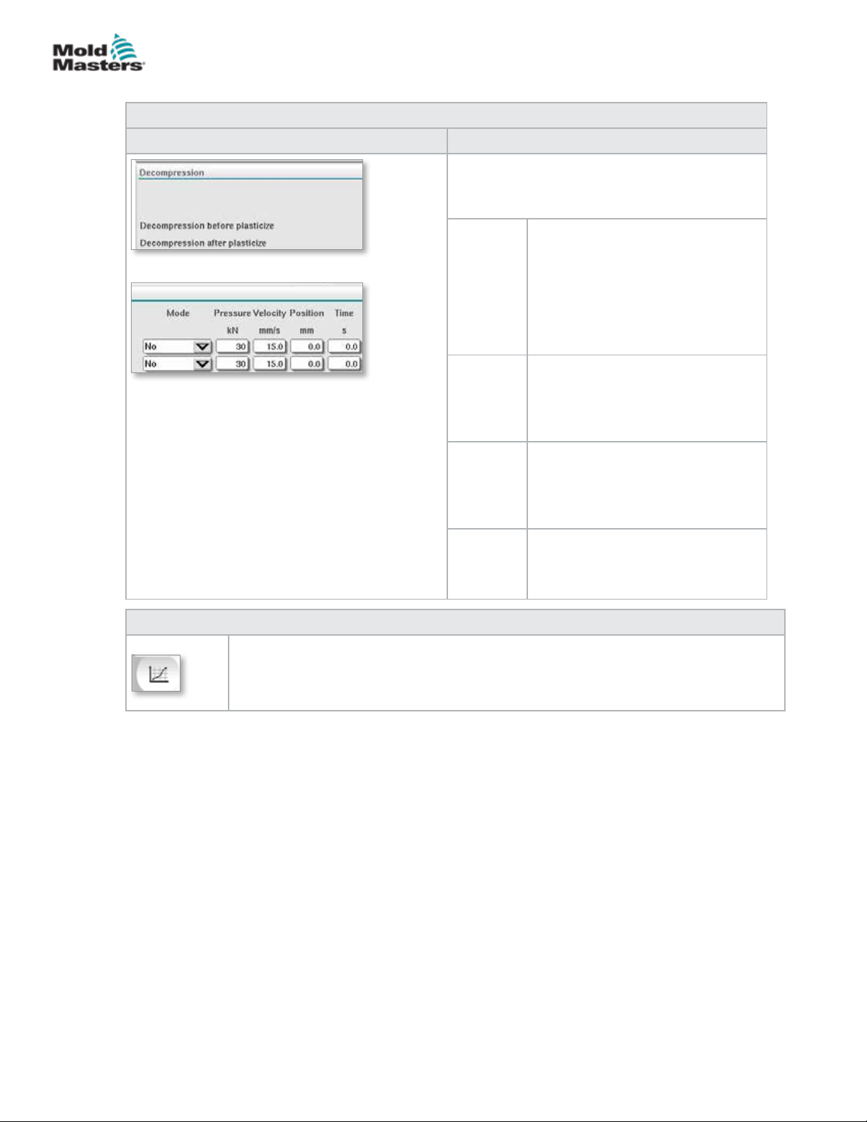
E-MULTI CONTROLLER HMI INTERFACE
Recovery Settings Screen - continued
Table 7-13 Recovery Settings Screen Components
Screen Components Description
Decompression
These settings apply only for manual and
automatic mode.
Mode Mode of decompression before
Pressure Species the pressure for the linear
Velocity Species the velocity for the linear
Position /
Time
plasticizing, with the following
selection options:
No: No decompression
Time: Decompression for a specied
time duration
Position: Decompression until a
specied screw position
screw movement.
This eld can only be edited when
'Time' or 'Position' mode has been
selected.
screw movement.
This eld can only be edited when
'Time' or 'Position' mode has been
selected.
Species the screw position or the
duration of the decompression.
The display is dependent on the
mode selected.
7-20
Table 7-14 Recovery Settings Screen Context Menu Buttons
Production Graphs
Navigates to the Production Graph Screen which provides real time data on the current
production process.
E-Multi Controller User Manual
© 2020 Mold-Masters (2007) Limited. All Rights Reserved.
Page 74
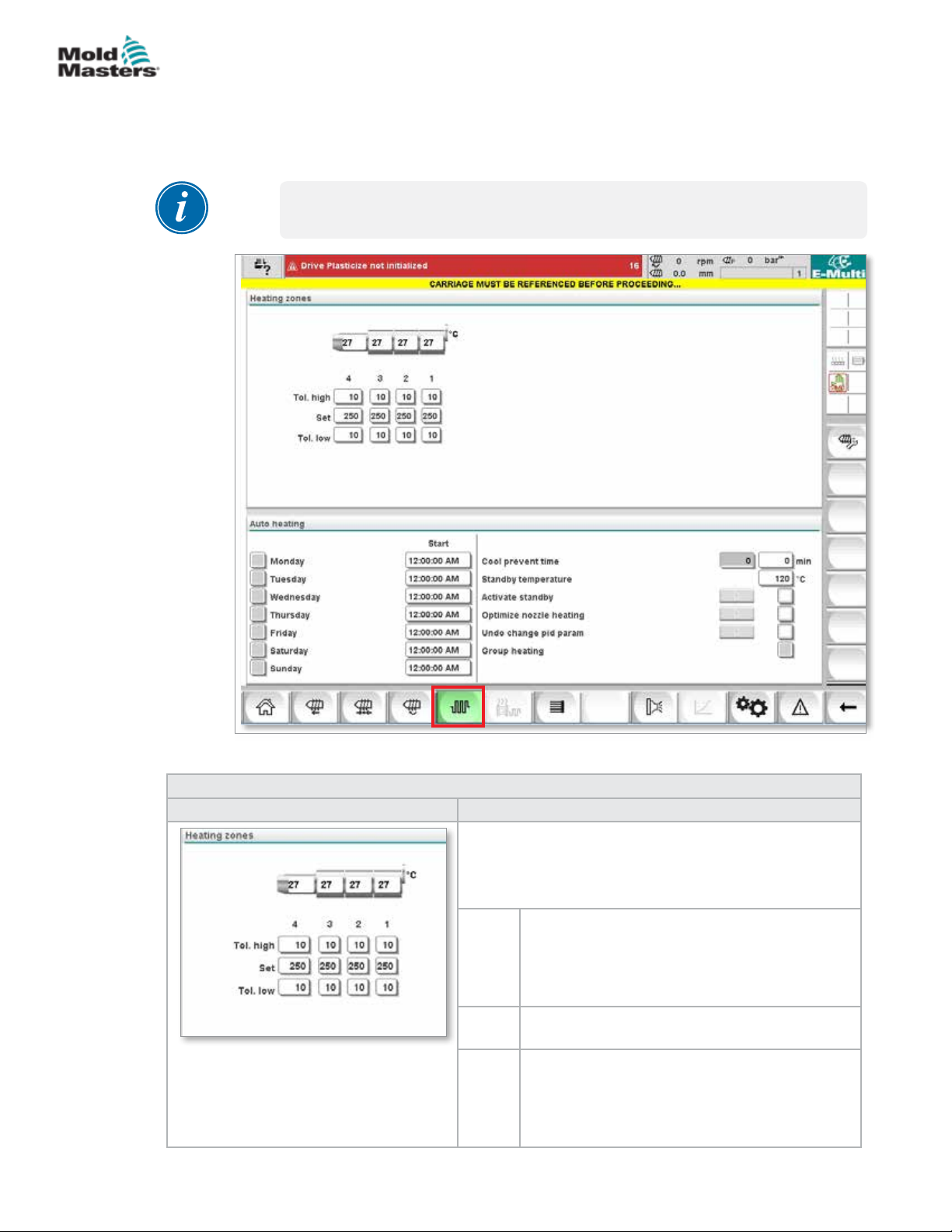
E-MULTI CONTROLLER HMI INTERFACE
7.9 Barrel Temperature Settings - Legacy
Controllers*
This screen is used to adjust temperature settings for the barrel heating
zones.
*NOTE
These screens were available only on certain systems prior to 2015.
7-21
Figure 7-7 Legacy style barrel temperature settings screen
Table 7-15 Legacy Style Barrel Temperature Setting Screen Components
Screen Component Description
© 2020 Mold-Masters (2007) Limited. All Rights Reserved.
Heating zones
The individual heating zones are graphically displayed
with the current temperature in the middle of each zone.
The display will depend on the number of heating zones.
Tol.
high
Set Species the temperature set-point value of the
Tol.
low
Species the high tolerance within which the
actual temperature of the heating zones must
sit. If this tolerance is exceeded an alarm will
be triggered. Only when all zones are within the
tolerance is movement of the screw possible.
corresponding heating zone (in degrees).
Species the low tolerance within which the
actual temperature of the heating zones must
sit. If this tolerance is exceeded an alarm will
be triggered. Only when all zones are within the
tolerance is movement of the screw possible.
E-Multi Controller User Manual
Page 75
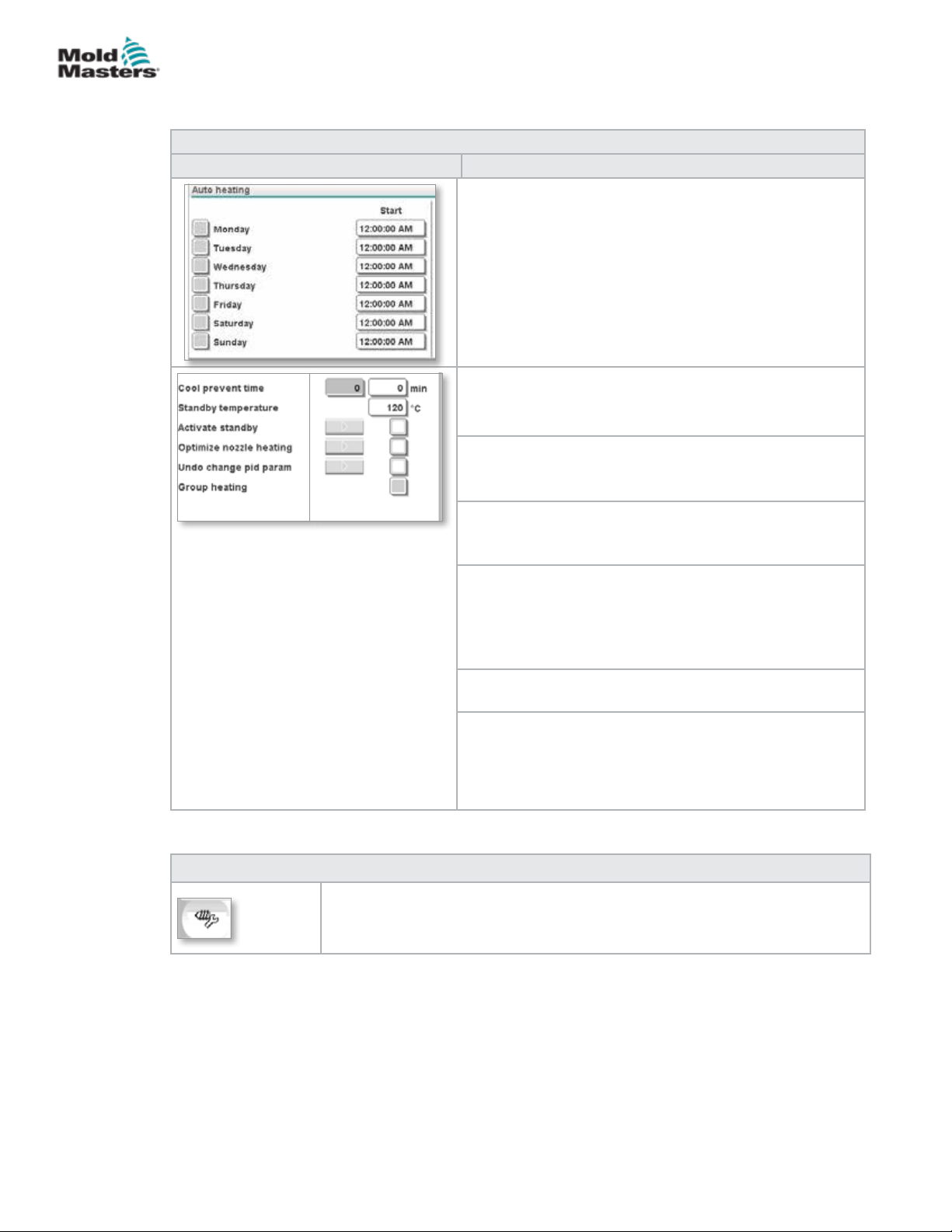
E-MULTI CONTROLLER HMI INTERFACE
Barrel Temperature Settings - Legacy Controllers* continued
Table 7-15 Legacy Style Barrel Temperature Setting Screen Components
Screen Component Description
Auto Heating
Barrel heats may be switched on automatically using this
feature.
Check the box next to the day to enable auto heat for that
day.
Barrel heats will turn on at the specied time.
Note: Heaters will stay on until manually turned o.
Soak Time
This is the amount of time the unit has to be at process
temperature before the screw can move.
Standby temperature
Temperature setpoint when Activate Standby is checked.
7-22
Activate standby
Barrel heating is switched to standby mode.
Standby temperature setpoints are used.
Optimize nozzle heating
Used to optimize heat zone PID tuning after adding a
heater, replacing a heater, changing the mold or after a
software update.
Optimization can only be done when the barrel is cold.
Undo change pid param
Reset heater PID tuning to pre-optimization values.
Group heating
When enabled, Group Heating monitors heat zones when
they are rst heated to process temperature and ensures
that all zones heat up at the same rate.
This feature is not required for standard congurations.
Table 7-16 Legacy Style Barrel Temperature Setting Screen Context Menu Buttons
Reference Settings
E-Multi Controller User Manual
© 2020 Mold-Masters (2007) Limited. All Rights Reserved.
Page 76
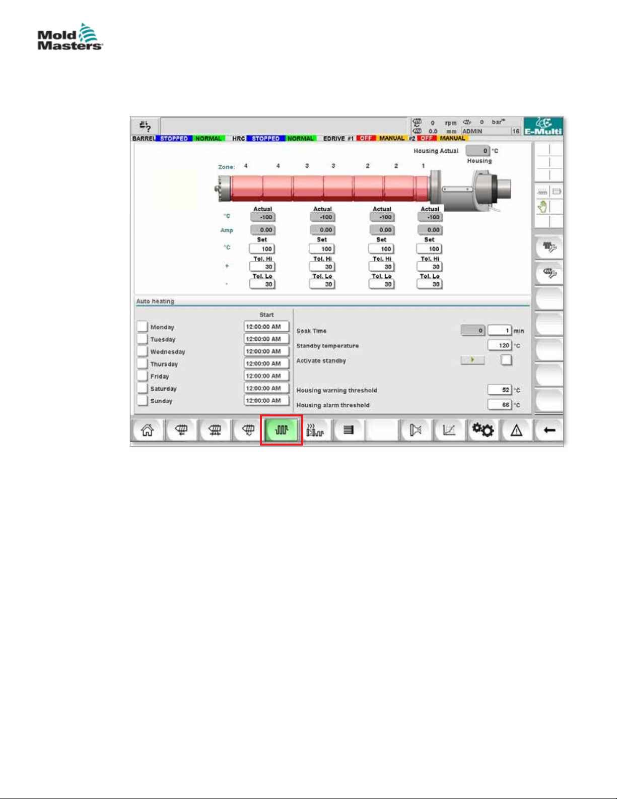
E-MULTI CONTROLLER HMI INTERFACE
7.10 Barrel Temperature Settings - Mold-Masters
Screen
This screen is used to adjust temperature settings for the barrel heating
zones.
7-23
Figure 7-8 Mold-Masters barrel temperature settings screen
© 2020 Mold-Masters (2007) Limited. All Rights Reserved.
E-Multi Controller User Manual
Page 77
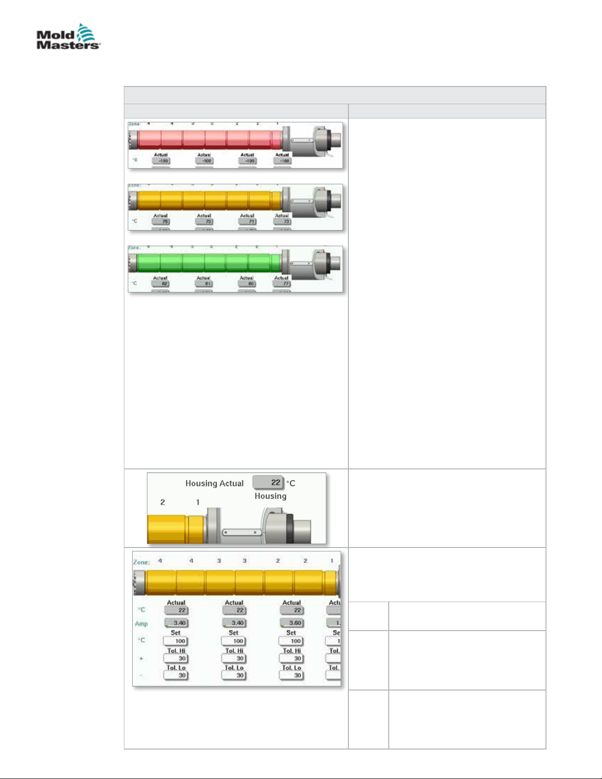
E-MULTI CONTROLLER HMI INTERFACE
Barrel Temperature Settings - Mold-Masters Screen continued
Table 7-17 Mold-Masters Barrel Temperature Screen Components
Screen Component Description
Zone Status - Visual Display
Referenced with the Top Bar Status Display
for information on the current condition.
The barrel temperature indicator zones will
change color depending on the temperature
of the corresponding barrel zone.
Green - Indicates barrel zone is at operating
temperature.
Yellow - Indicates barrel zone is close to
operating temperature but auto soak has not
completed.
Red - Indicates barrel is zone is outside of set
temperature window.
7-24
When AutoSoak is used, the system will wait
until the barrel temperature is just below the
setpoint and will attempt to turn the feed
screw using low torque. If the screw can turn,
the AutoSoak status will change to Pass and
the color will change to green.
When AutoSoak is not used, the system will
wait until the barrel temperature is just below
the setpoint and will start the soak timer. After
the soak timer completes, the soak status will
change to Pass and the color will change to
green.
Housing Actual
Actual temperature of barrel housing.
Heating Zones
The individual heating zones are graphically
displayed with real time temperature and
current feedback displayed below each zone.
Set Species the temperature set-point
value of the heating zone.
E-Multi Controller User Manual
Tol Hi Species the temperature above
which the zone will be out of
tolerance. If the temperature
exceeds this value, an alarm is
triggered.
Tol Lo Species the temperature below
which the zone will be out of
tolerance. If the temperature
drops below this value, an alarm is
triggered.
© 2020 Mold-Masters (2007) Limited. All Rights Reserved.
Page 78
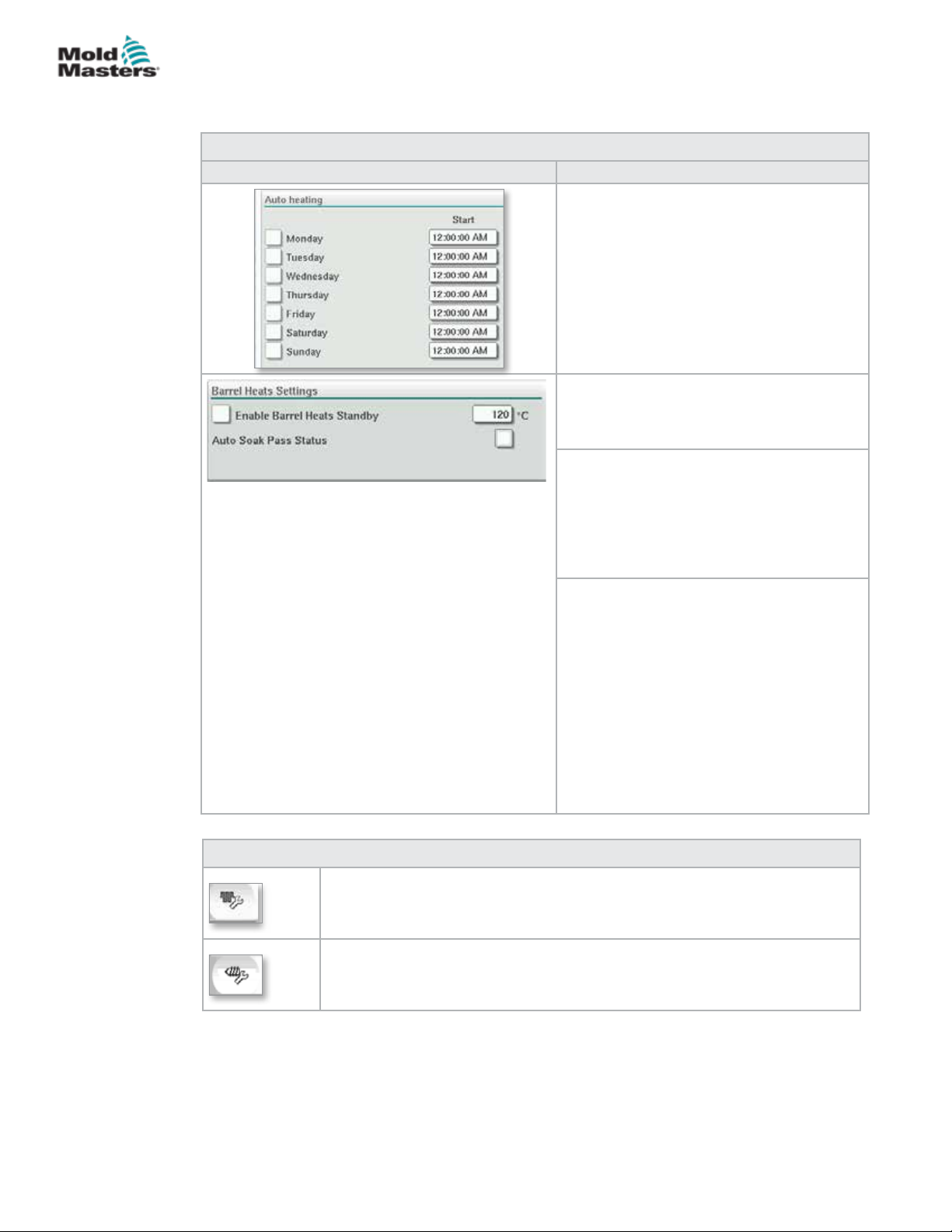
E-MULTI CONTROLLER HMI INTERFACE
Barrel Temperature Settings - Mold-Masters Screen continued
Table 7-17 Mold-Masters Barrel Temperature Screen Components
Screen Component Description
Auto Heating
Barrel heats may be switched on
automatically using this feature. Check the
box next to the day to enable auto heat for
that day.
Barrel heats will turn on at the specied time.
Note: Heaters will stay on until manually
turned o.
AutoSoak Pass Status
This indicator shows whether the AutoSoak
has been successfully completed or not after
all the barrel heats are up to temperature.
Standby Temperature
When Standby is activated, all barrel zone
temperatures will be decreased by this
amount.
For example, if the barrel temperature
setpoint is 200C and the Standby setpoint is
120C, the barrel heat will be reduced to 80C.
Activate Standby: Standby mode holds the
heating zones at a preset temperature during
a stop in production. Standby temperature is
usually lower than processing temperature
but higher than ambient temperature.
7-25
On: temperature is set to the Standby
temperature. No screw movement is
possible.
O: temperature is reset to the production
operating temperatures. Screw movement is
possible.
Table 7-18 Mold-Masters Temperature Settings Screen Context Menu Buttons
Hot Runner Control Setup Screen
Navigates to the Integrated Hot Runner Control Setup screen where
integrated hot runner control settings can be adjusted.
Reference Settings
© 2020 Mold-Masters (2007) Limited. All Rights Reserved.
E-Multi Controller User Manual
Page 79
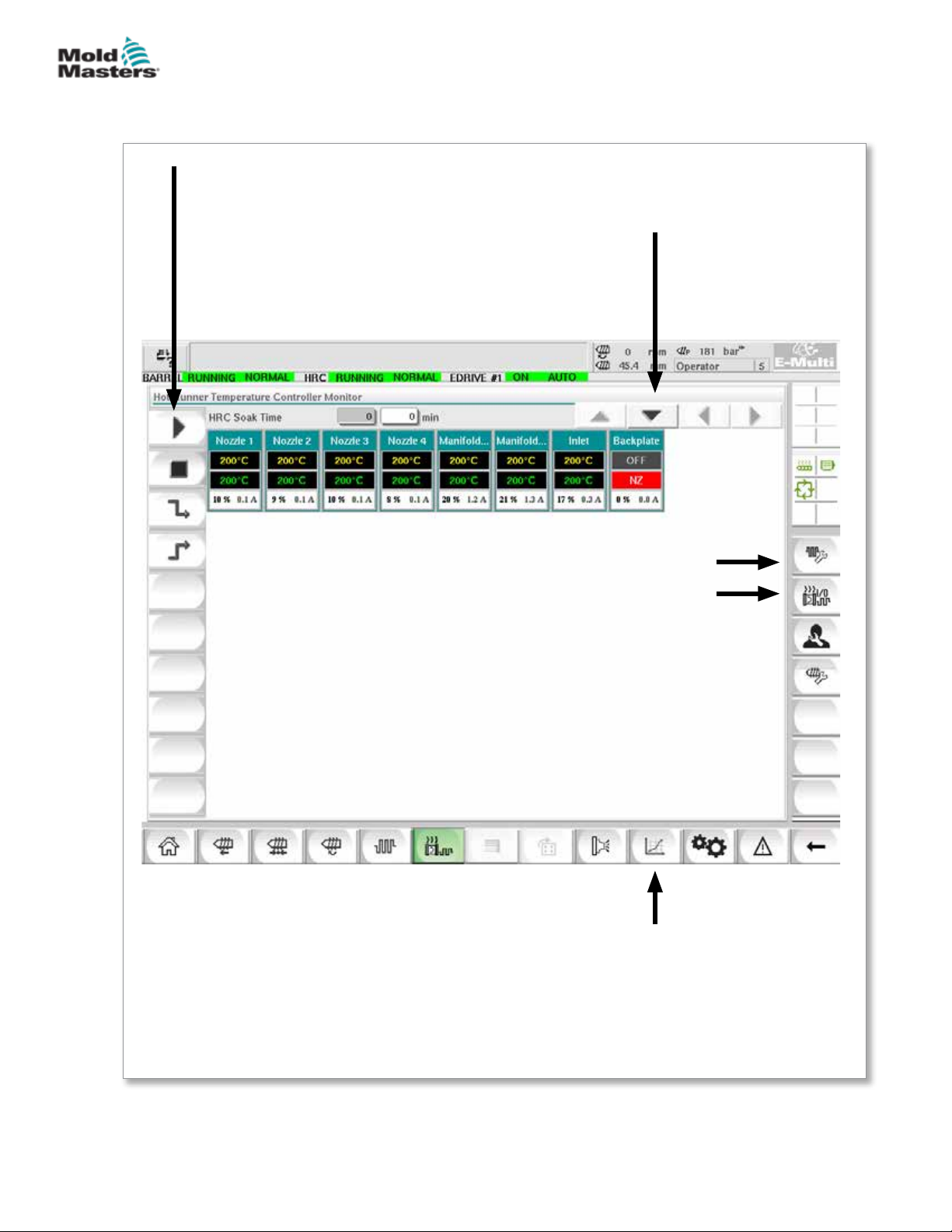
E-MULTI CONTROLLER HMI INTERFACE
7.11 Integrated Hot Runner Temperature Control
(Option)
7-26
Left Bar - Hot Runner
Temperature Control
Buttons
Scroll Buttons
For scrolling through the zone
rows and columns
Supervisor Level Settings
Hot Runner Control Setup Screen
Hot Runner Control Utilities Screen
Figure 7-9 Integrated hot runner controller overview screen
E-Multi Controller User Manual
Lower Bar - E-Multi Screen
Navigation and System
Buttons
See “Bottom Bar - Screen Navigation
Buttons” on page 7-6.
© 2020 Mold-Masters (2007) Limited. All Rights Reserved.
Page 80
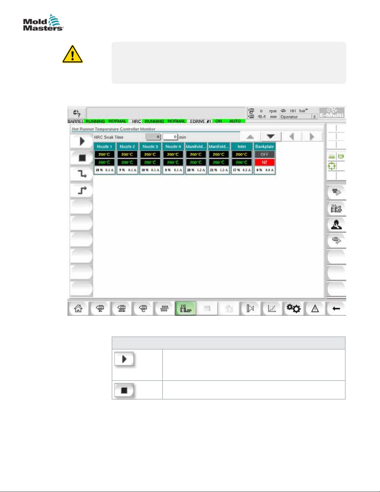
E-MULTI CONTROLLER HMI INTERFACE
7.11.1 Monitor Screen
WARNING
Selecting [Stop] does not remove voltage from the heaters. Selecting
[Stop] sets all the target temperatures to zero. DO NOT try to change fuses
or disconnect units while in this mode.
This screen is the main screen for the integrated hot runner temperature
control and provides an overview of operational data.
7-27
Figure 7-10 Hot runner controller monitor screen
© 2020 Mold-Masters (2007) Limited. All Rights Reserved.
Table 7-19 Monitor Screen Control Buttons
[Run] switches on all heat zones, so that they independently rise
up to their set point temperatures.
[Stop] switches o all heat zones.
E-Multi Controller User Manual
Page 81
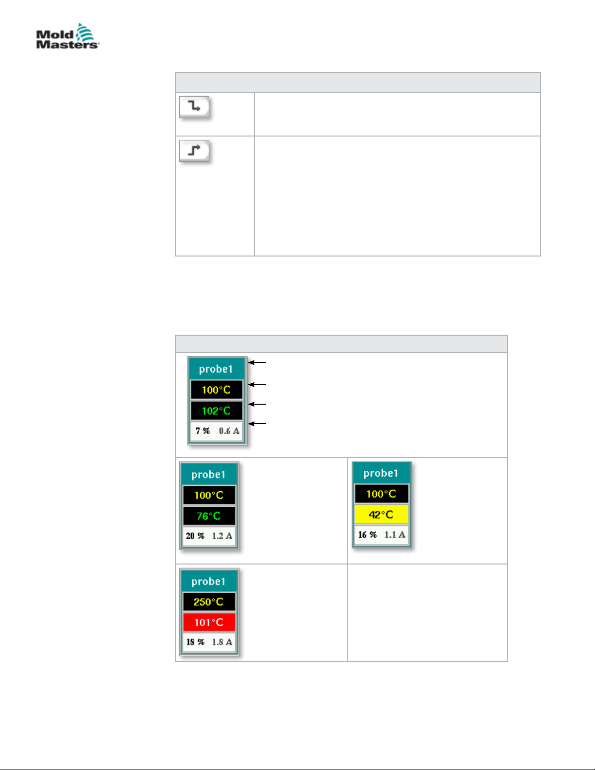
E-MULTI CONTROLLER HMI INTERFACE
Monitor Screen - continued
Table 7-19 Monitor Screen Control Buttons
[Standby] This mode is used when the molding cycle is stopped
for a short time.
Standby remains active until the run button is pressed.
[Boost] This mode allows you to temporarily raise the
temperatures of selected zones for a set period. Boost values
are entered on the Setup screen on a zone by zone basis. Any
zones that are left at zero will not respond to a Boost request
but stay at their normal operating temperature. During a Boost
command, the Boost time set in the global conguration is the
main determining factor. If, on a slow responding manifold, you
set a high Boost temperature while the Boost time is set short,
then the zone is unlikely to reach your set Boost temperature
before the Boost time limit expires.
Heat Zone Display
Each heat zone is displayed as a control panel that carries ve pieces of
information. The window changes color to show normal and alarm states.
7-28
Table 7-20 Heat Zone Display
Zone Identier or Alias
Actual Zone Temperature
Temperature Set Point
Power Level / Current
Green lettering
on a black
background:
Temperature
within range.
White lettering on
a red background:
Fatal error or
temperature
exceeds alarm
limits.
Black lettering on a
yellow background:
Temperature zone
is heating.
E-Multi Controller User Manual
© 2020 Mold-Masters (2007) Limited. All Rights Reserved.
Page 82
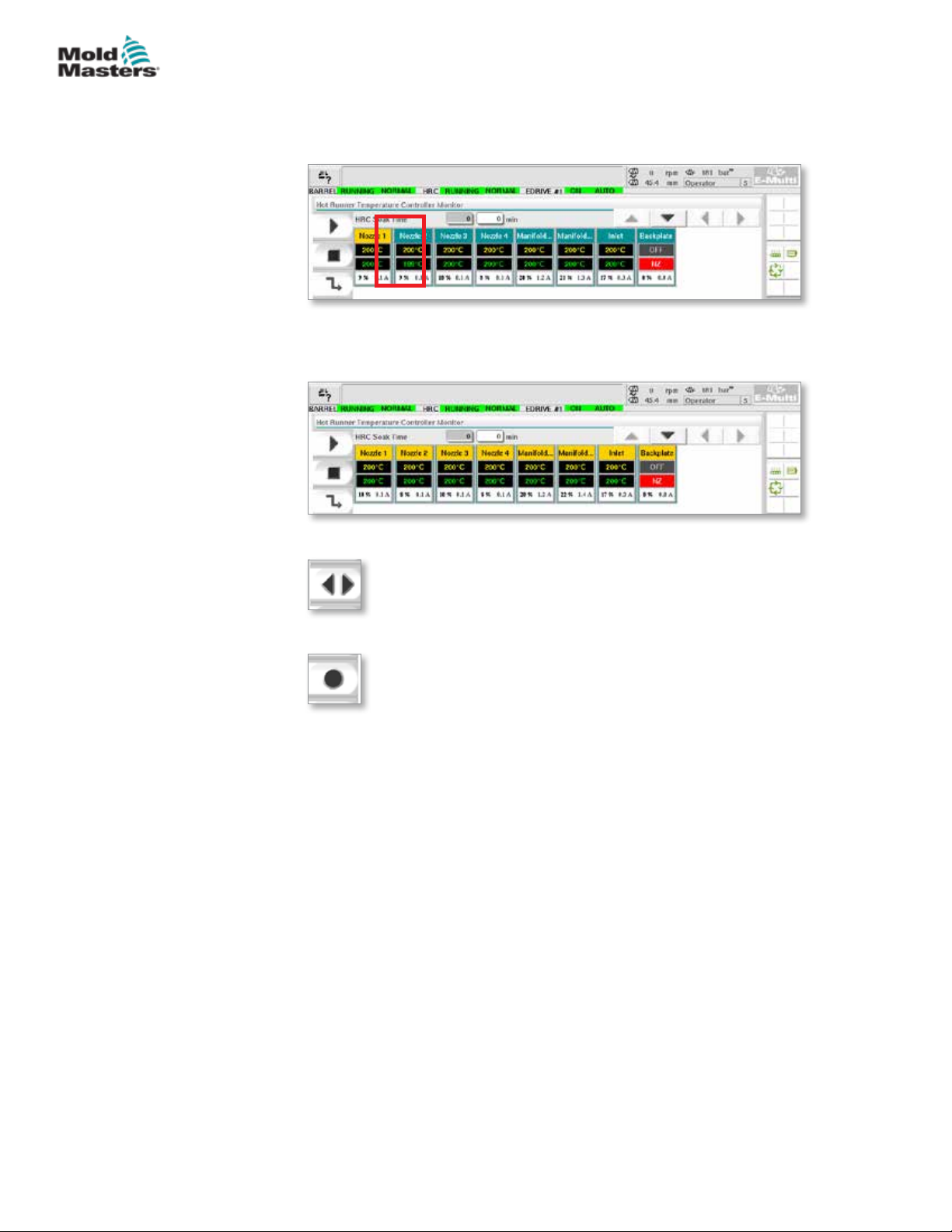
E-MULTI CONTROLLER HMI INTERFACE
Adjust Heat Zone Set Points
Select the desired zone(s):
a) To select a single zone tap the desired heat zone panel.
b) To select a group of zones:
Tap the rst zone panel.
Tap the last zone panel.
7-29
Tap the [Group] button:
1. Tap the [Set] button to display the keypad:
2. Choose the set-point mode. The options are [Auto], [Man] and [Slave],
as described below.
Auto - Tap [Auto] and enter the required zone temperature. This is the
default mode for the controller [i.e. closed loop] where the controller output
is determined as a set temperature and which relies on feedback from the
thermal sensor.
Manual - Tap [Man] and enter the percentage power. This is an optional
mode [i.e. open loop] where the controller output is xed at a set power level,
which is determined by the operator.
Slave a Zone - Tap [Slave] and select a similar Master zone from the zone
list. For more information see “Slaving Zones” on page 7-30.
3. Use the number keys to enter the set point value.
4. Tap [Enter] to save the set point value in the controller.
© 2020 Mold-Masters (2007) Limited. All Rights Reserved.
E-Multi Controller User Manual
Page 83
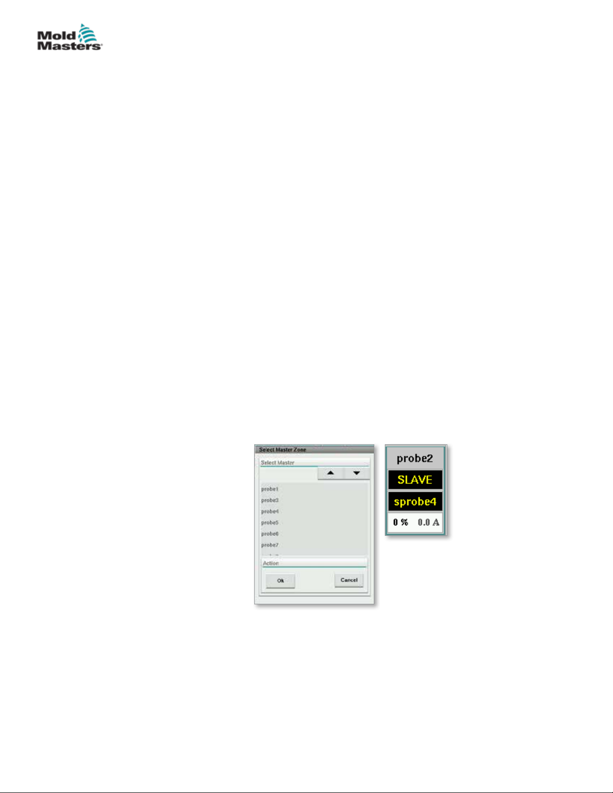
E-MULTI CONTROLLER HMI INTERFACE
Other Keypad Buttons
[Del] - Delete: removes the last number typed in.
[Esc] - Closes the keypad and does not enter the value into the controller.
[O] - Turns the selected zone o.
Slaving Zones
This mode can be used if a thermal sensor has failed. Rather than switching
to manual, this option allows a faulty zone to be slaved to a working one. The
temperature on the faulty zone then mimics the good zone that is working in
auto (or closed loop).
There are several points to remember when slaving zones.
1. Zones can only be slaved to zones of the same type; i.e. manifold to
manifold or probe to probe.
2. Zones that are already slaved to a master cannot be used as masters for
another slave.
3. Zones cannot be slaved in loops. If zone 2 is slaved to zone 1, zone 1
cannot be slaved to zone 2.
7-30
4. Zones should only be slaved to masters of a similar power rating. Slaving
a zone to master of a signicantly dierent power rating may result in
incorrect temperature regulation.
5. When a zone is slaved its temperature readout will be replaced with
SLAVE.
A slave zone will be identied along with the zone it is slaved to (see below).
E-Multi Controller User Manual
© 2020 Mold-Masters (2007) Limited. All Rights Reserved.
Page 84
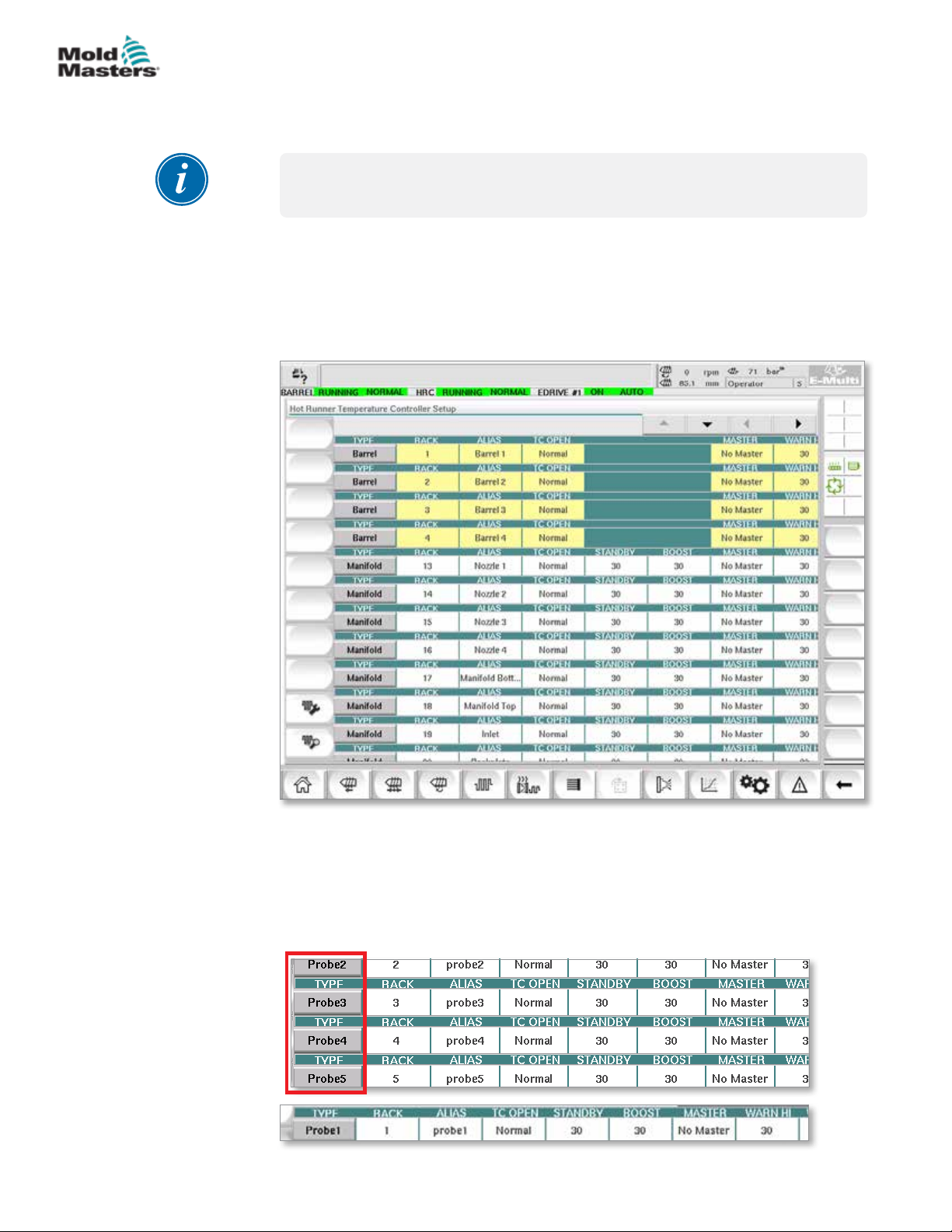
E-MULTI CONTROLLER HMI INTERFACE
7.11.2 Setup Screen (Supervisor Level)
The Setup screen is used to set heat zone parameters and congure some
global parameters.
NOTE
The Setup screen can only be accessed with supervisor or higher credentials.
Use the scroll bars to see information for all the cards within the controller.
The same grid that displays this information is also used to set up the heat
zone parameters. Heat zone set points such as Set Temperature and Actual
Temperature are displayed here but cannot be changed from this screen.
They are changed from the Monitor Screen. See “Table 7-19 Monitor Screen
Control Buttons” on page 7-27 for the description of elements.
7-31
Figure 7-11 Setup screen (supervisor level)
Heat Zone Display
The rst column displays all the heat zones detected on the controller. This
column is used to select heat zones in order to change their parameters.
Zone parameters are identied by colored column headings.
© 2020 Mold-Masters (2007) Limited. All Rights Reserved.
E-Multi Controller User Manual
Page 85
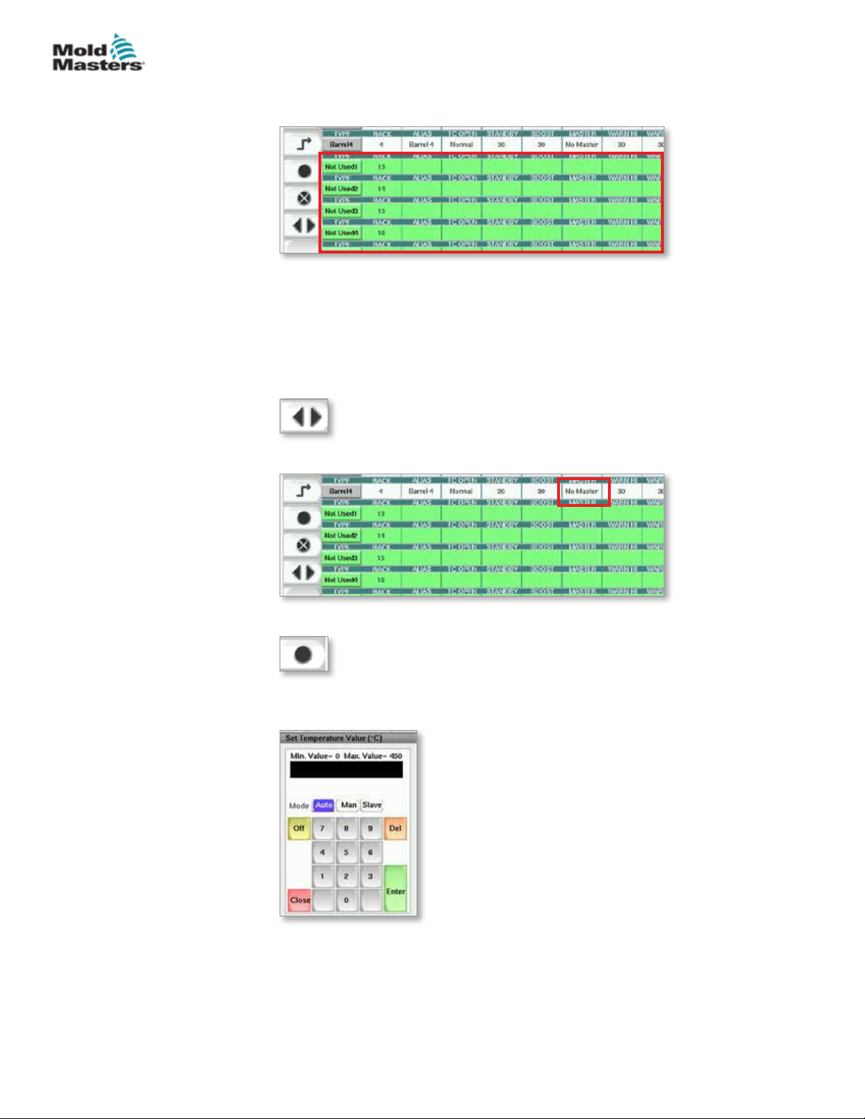
E-MULTI CONTROLLER HMI INTERFACE
Adjust Heat Zone Set Points
Heat Zone parameters are accessed within the Setup screen grid.
1. Select the desired zone row(s):
a) To select a single zone row tap the desired heat zone row.
b) To select a group of zones:
Tap the rst zone row.
Tap the last zone row.
Tap the [Group] button.
2. Tap the parameter column.
7-32
3. Tap the [Set] button to display the keypad.
4. Set the value. Tap [Enter] to save the new parameter setting in the
controller.
E-Multi Controller User Manual
© 2020 Mold-Masters (2007) Limited. All Rights Reserved.
Page 86
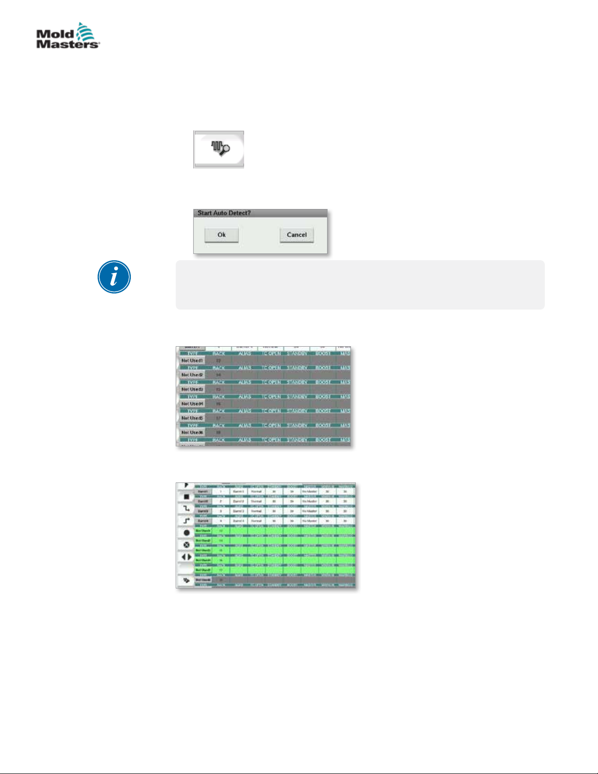
E-MULTI CONTROLLER HMI INTERFACE
Detect Heat Zones and Congure Zone Types
The console can run an automatic zone detection routine to detect the zones
available on the controller cards. This needs to be done during initial setup of
the controller or if a card change takes place.
1. Tap [Auto Detect] to open the Auto Detect conrmation dialog.
2. Tap [OK] to run the zone detection routine. Wait for Auto Detect to nish
Auto detecting zones may take up to 5 minutes.
NOTE
Auto detect will reset all barrel and hot runner controller temperature
setpoints.
7-33
All available zones will be displayed on the Setup screen. They will be autonumbered and display as Not Used without parameter settings.
Once auto detection completes, the setup area will be populated with heater
zones. The number of zones detected should always be an even number.
3. To setup zone types:
a) Tap the rst zone of the same type.
© 2020 Mold-Masters (2007) Limited. All Rights Reserved.
E-Multi Controller User Manual
Page 87
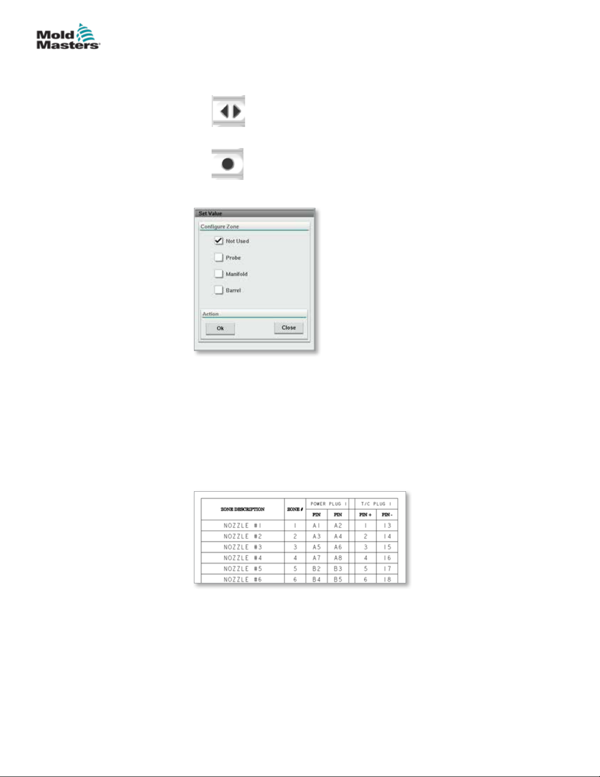
E-MULTI CONTROLLER HMI INTERFACE
Detect Heat Zones and Congure Zone Types - continued
b) Tap the last zone of the same type.
c) Tap group.
d) Tap set.
The congure heat zone window will open:
7-34
4. Select the zone type:
• [Not Used] - to switch o unwanted zones.
• [Probe] - Nozzle heat control required.
• [Manifold] - Manifold heat control required.
5. Tap the type to place a checkmark in the desired box.
6. Tap [OK].
7. Refer to the hot runner wiring diagram for a table showing heater type and
position of each zone. A sample table is shown for reference:
E-Multi Controller User Manual
© 2020 Mold-Masters (2007) Limited. All Rights Reserved.
Page 88
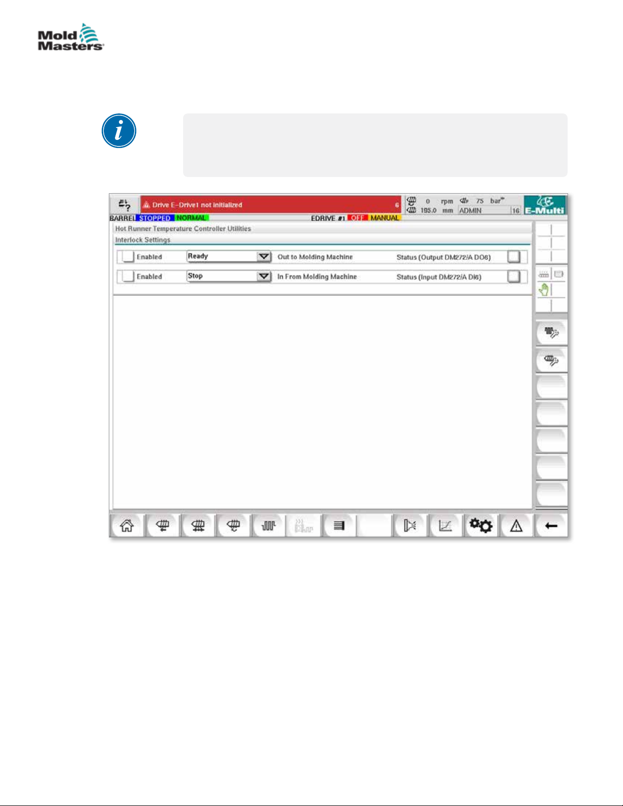
E-MULTI CONTROLLER HMI INTERFACE
7.11.3 Utilities Screen (Supervisor Level)
The Integrated Hot Runner Controller Utilities screen is used to change the
settings of the interlocks with the molding machine. These interlock signals
are not necessary for operation but are supplied for customer use if needed.
NOTE
The Utilities screen can only be accessed by supervisor credentials or
above level authorized personnel. See the electrical schematic for further
information.
7-35
Figure 7-12 Utilities screen (supervisor level)
© 2020 Mold-Masters (2007) Limited. All Rights Reserved.
E-Multi Controller User Manual
Page 89
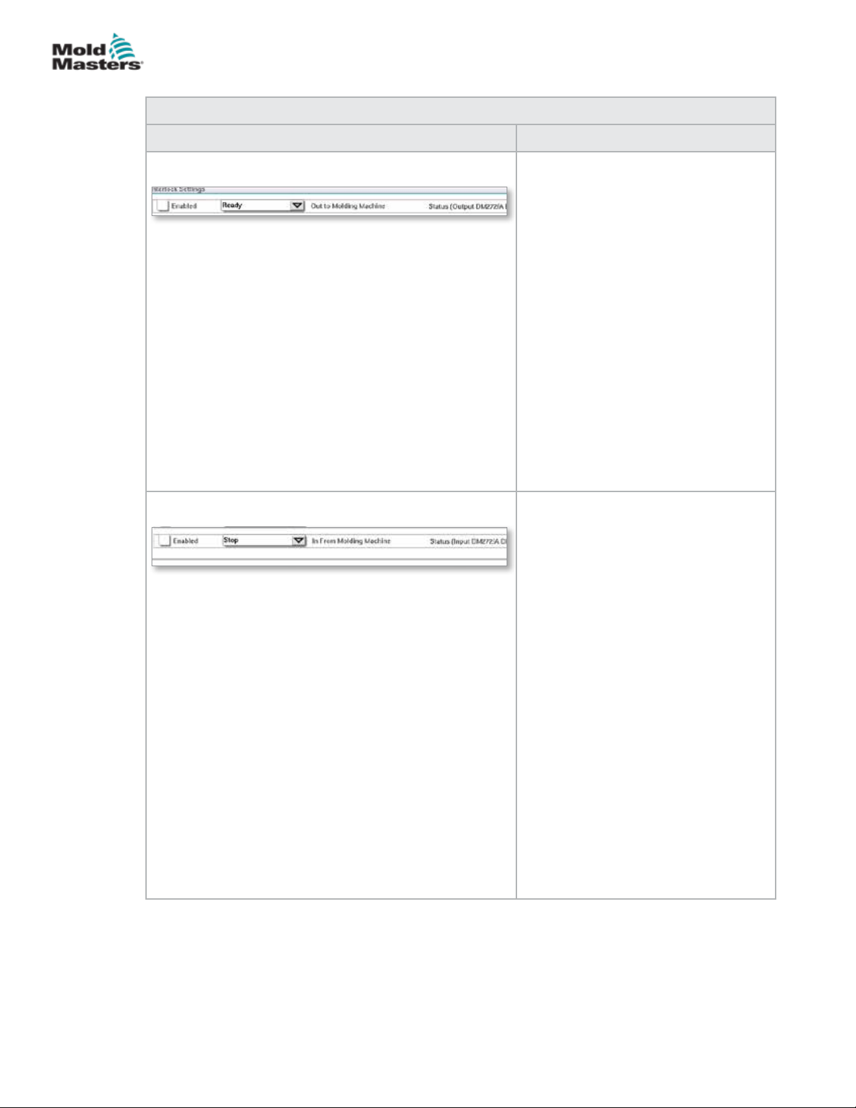
E-MULTI CONTROLLER HMI INTERFACE
Utilities Screen (Supervisor Level) - continued
Table 7-21 Utility Screen Elements
Screen Components Description
Interlock Settings - Out to Molding
Machine
Enabling this interlock sends a signal
to the molding machine when the
controller is ready (i.e. heat zones are
at temperature, there are no alarms and
controller is in RUN mode).
Tap the drop down box and select
[Ready].
Tap the [Enabled] box and an interlock
window will open.
Tap the checkmark to enable the
interlock.
The status (On = green) / (O = white)
and PLC address are displayed on the
right.
Interlock Settings - In from Molding
Machine
7-36
Enabling this interlock accepts a signal
from the molding machine that forces
the E-Multi temperature controller into
the selected mode of operation.
Tap the drop down box and select from
the following Modes:
Stop
Run
Standby
Boost
Tap the [Enabled] box and an interlock
window will open.
Tap the checkmark to enable the
interlock.
The status (On = green) / (O = white)
and PLC address is displayed on the
right.
E-Multi Controller User Manual
© 2020 Mold-Masters (2007) Limited. All Rights Reserved.
Page 90
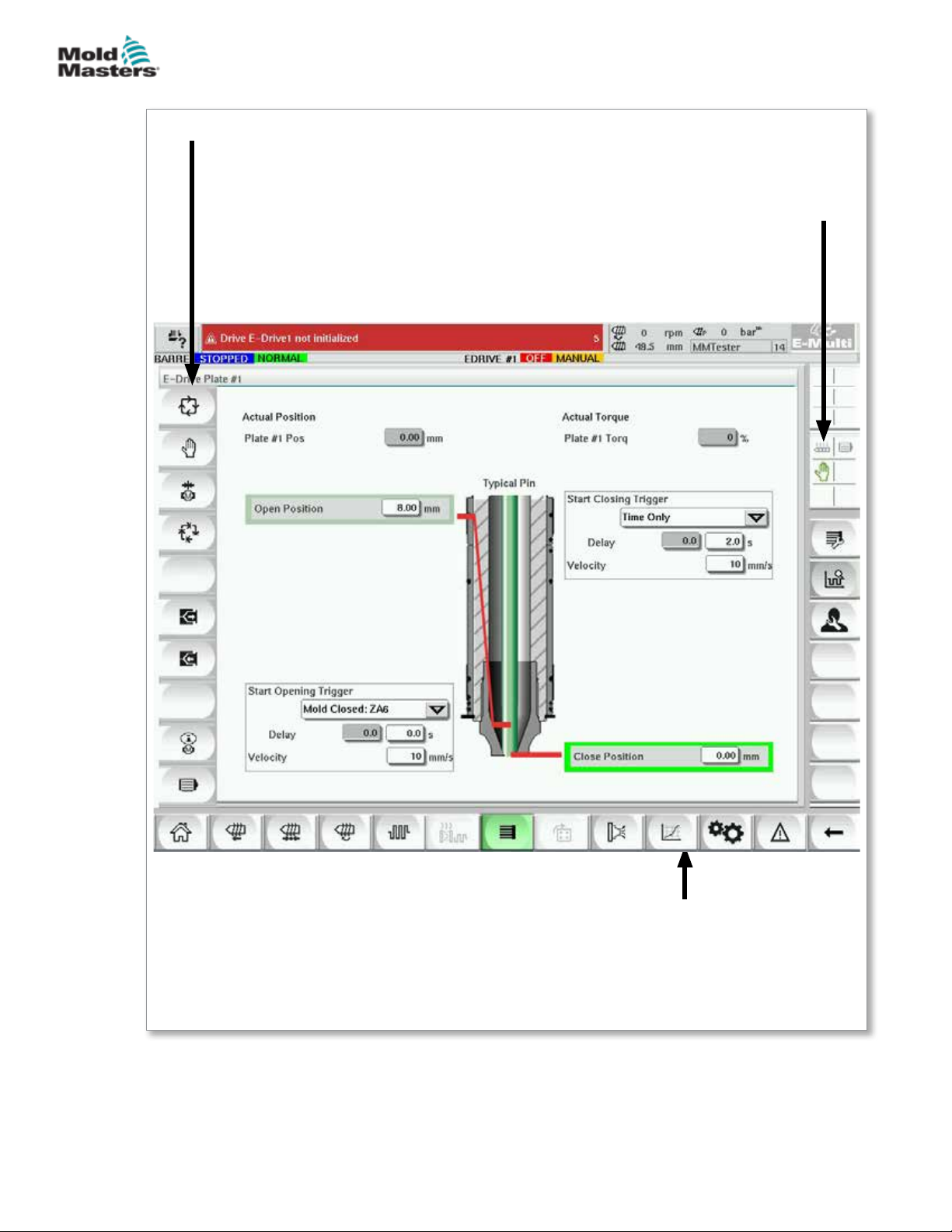
E-MULTI CONTROLLER HMI INTERFACE
7.12 Integrated E-Drive Control (Option)
Left Bar - E-Drive Control Buttons
7-37
E-Drive Context Buttons
Includes access to overview and setup
screens for each E-Drive Plate.
Figure 7-13 E-Drive control screen components
© 2020 Mold-Masters (2007) Limited. All Rights Reserved.
Lower Bar - E-Multi Screen
Navigation and System Buttons
See “Bottom Bar - Screen Navigation
Buttons” on page 7-6 .
E-Multi Controller User Manual
Page 91
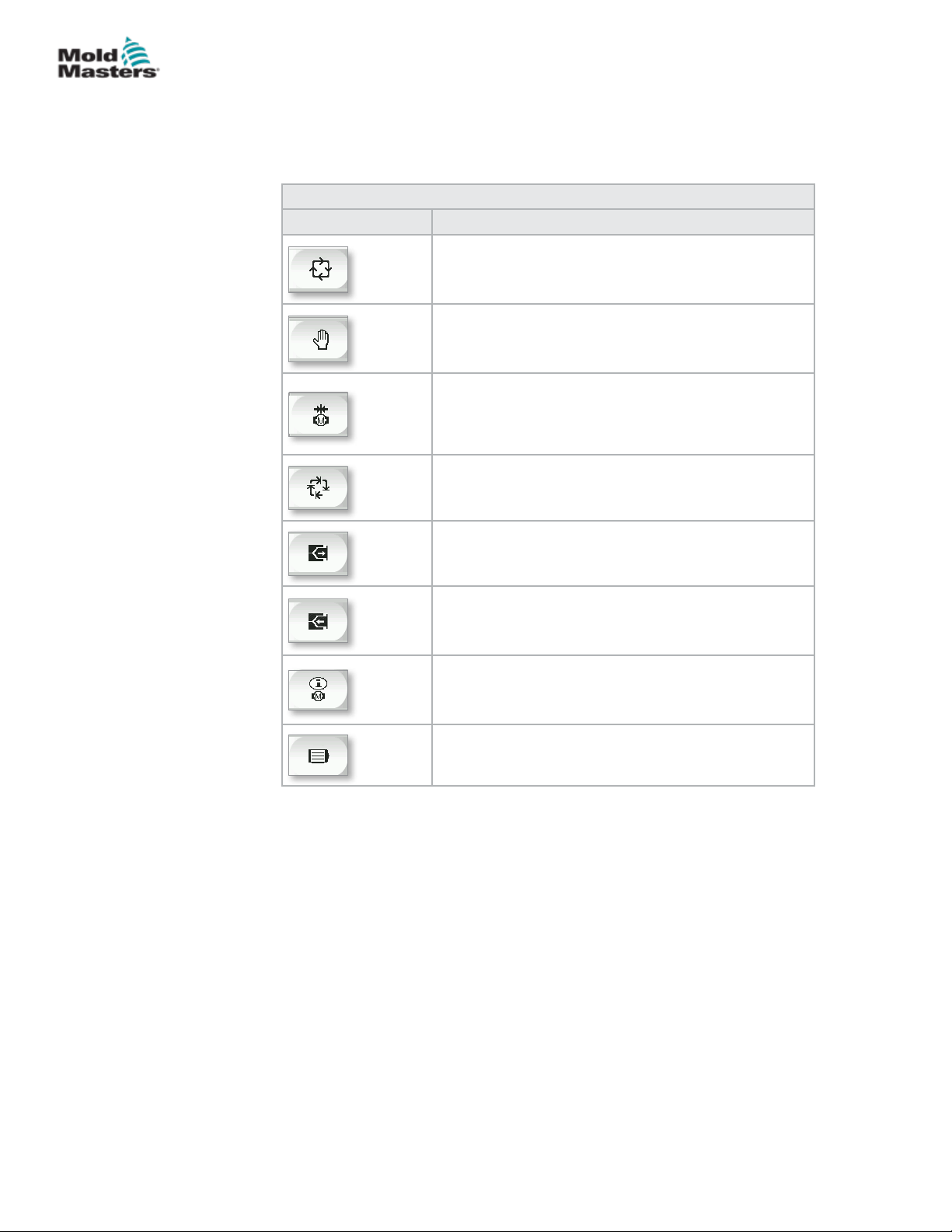
E-MULTI CONTROLLER HMI INTERFACE
7.12.1 E-Drive Control Buttons
On the left hand edge of each screen is the E-Drive button bar.
To operate functions simply tap the button using either your ngers or a blunt
pointer.
Table 7-22 E-Drive Control Buttons
Button Description
Auto – Required to automatically sequence the
E-Drive controller based on external triggers.
Manual – Used for Home and jog mode.
Home – Used to reference the E-Drive controller (set
the forward – 0.00) position.
Step ON – Each press of the step button will step the
E-Drive controller through one step of the automatic
sequence.
7-38
Jog Forward- used to manually move the plates
forward. Position is ignored. Only available in setup
mode.
Jog Backward – used to manually move the plates
back. Position is ignored. Only available in setup
mode.
Servo Drive Management functions.
Servo State - used to turn the E-Drive servo drive
on and o. Button will be green when servos are
enabled.
E-Multi Controller User Manual
© 2020 Mold-Masters (2007) Limited. All Rights Reserved.
Page 92

E-MULTI CONTROLLER HMI INTERFACE
7.13 Overview Screen
This screen gives an overview of the Integrated E-Drive operation. If more
than one E-Drive plate is in use, additional context menu buttons will be
accessible on the right. However, if Master mode is used, any slaved plates
will not be accessible on the right, only master plates.
7-39
Figure 7-14 E-Drive controller overview screen
Table 7-23 E-Drive Overview Screen Elements
Screen Elements Description
© 2020 Mold-Masters (2007) Limited. All Rights Reserved.
This eld shows the actual plate position relative to the
forward hardstop position when the plate was last referenced
(See Homing on next page).
This eld shows the real-time motor torque for the plate 1
motor.
The [Start Opening Trigger] is selected from the drop down
list. See Trigger Conguration.
A time delay may also be added.
The [Set Velocity] button opens a dialog where users may
further adjust settings.
E-Multi Controller User Manual
Page 93
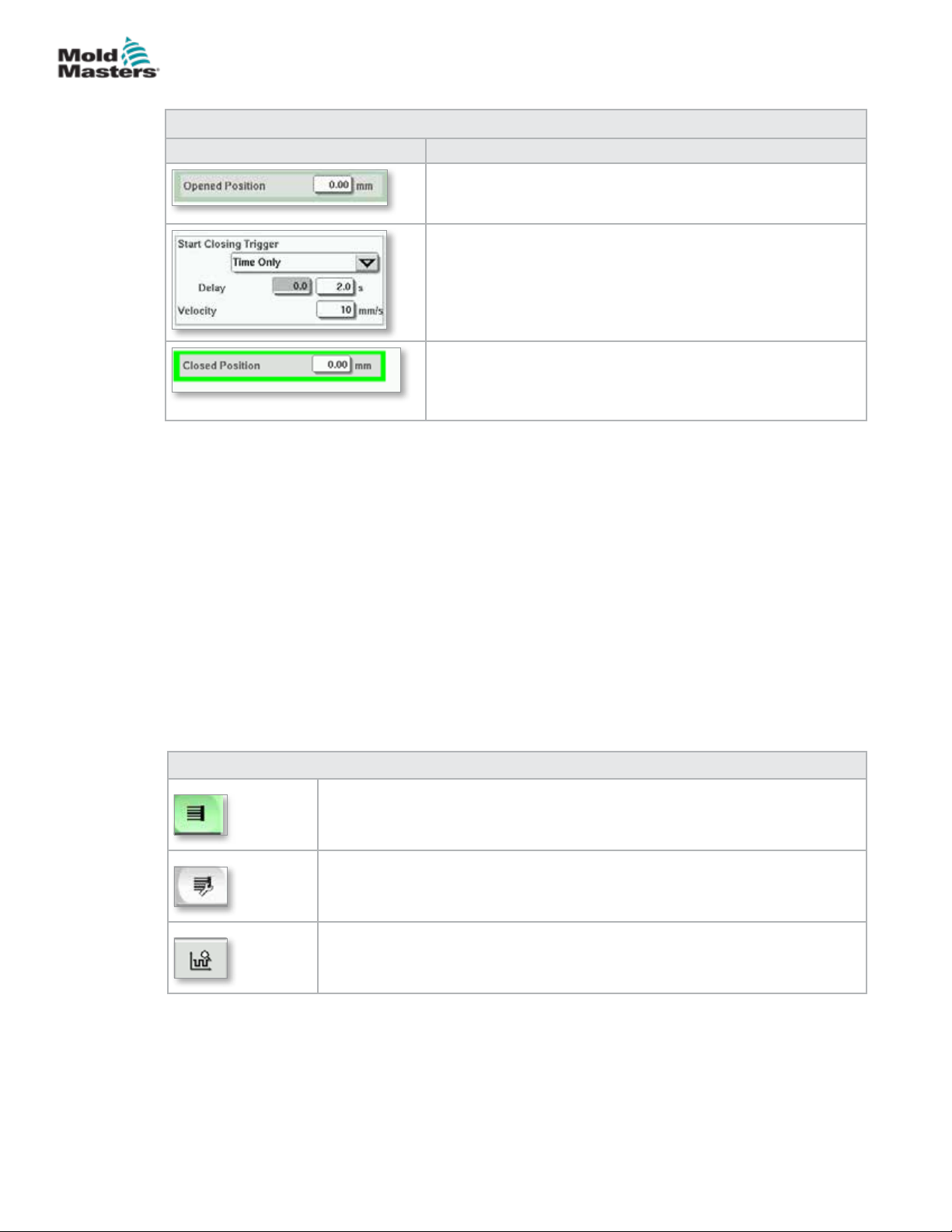
E-MULTI CONTROLLER HMI INTERFACE
Overview Screen - continued
Table 7-23 E-Drive Overview Screen Elements
Screen Elements Description
When the trigger conditions in the rst step are met, the
E-Drive controller will move the plate to the [Opened
position]. The actual open position is displayed here.
The [Start Closing Trigger] initiates the E-Drive closing
sequence.
The trigger is selected from the drop down list.
A time delay can also be added.
The [Set Velocity] button opens a dialog where users can
further adjust settings.
When the trigger conditions in the step above are met,
the E-Drive controller will move the plate to the [Closed
Position]. This also represents the starting position for the
next cycle.
7.13.1 Homing
Prior to running the E-Drive, the pin position must rst be referenced.
7-40
1. The E-Multi must be in setup mode and the E-Drive Servo must be turned
ON.
2. Press the [Home] button to initiate the automatic reference cycle, which is
described below.
STEP 1 – Move pins all the way back (IN) to the hardstop.
STEP 2 – Move pins all the way forward (OUT) to the hardstop.
STEP 3 – Calibrate this position as 0.00.
STEP 4 – Move the pins to the Closed Position.
3. The E-Drive can now be run in step mode or switched to Auto mode.
Table 7-24 E-Drive Screen Context Menu Buttons
E-Drive Overview Screen
Goes to the Integrated Hot Runner Control Setup screen where Integrated
Hot Runner Control settings can be adjusted.
E-Drive Settings Screen
Goes to the E-Drive Settings screen where settings can be adjusted.
Production Graph - Customizable view.
E-Multi Controller User Manual
© 2020 Mold-Masters (2007) Limited. All Rights Reserved.
Page 94
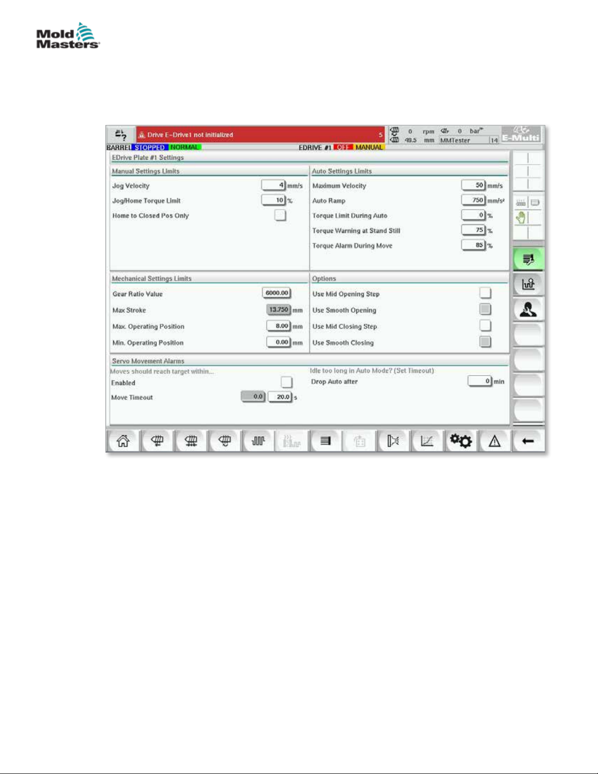
E-MULTI CONTROLLER HMI INTERFACE
7.14 Settings Screen (Supervisor Level)
This screen gives an overview of the Integrated E-Drive operation. If more
than one E-Drive plate is in use, additional context menu buttons will be
accessible on the right. However, if Master mode is used, any slaved plates
will not be accessible on the right, only master plates.
7-41
Figure 7-15 E-Drive setting screen
© 2020 Mold-Masters (2007) Limited. All Rights Reserved.
E-Multi Controller User Manual
Page 95
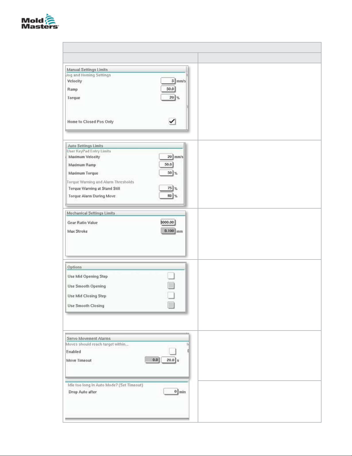
E-MULTI CONTROLLER HMI INTERFACE
Settings Screen (Supervisor Level) - continued
Table 7-25 E-Drive Settings Screen Elements
Screen Elements Description
Manual Settings Limits
Sets the maximum limits available for
adjustment when in manual mode.
Home to Closed Position Only
The plate moves to home position, nds the
hard stop and does not check the stroke by
going to the other hard stop.
Auto Settings Limits
Sets the maximum limits available for
adjustment by the operator on the overview
screen.
Torque Warning and Alarm Thresholds
Sets the threshold (%) at which warnings and
alarms would be generated.
7-42
Mechanical Settings Limits
Gear Ratio Value: This is the overall rotational
motor degrees per each linear mm of stroke.
Maximum Stroke: This the maximum stroke
set for the E-Drive plate. This is set at the
factory.
Options
A mid opening or closing step may be
activated here.
If activated, elds for setting position and delay
will be available on the Overview screen.
Smooth opening/closing
E-Drive plate transitions from one step to
another step without stopping.
Servo Movement Alarms
Moves should reach target within the specied
time. If the position is not reached, the system
will fault.
Enabled - check to enable
Time setting after which it times out.
E-Multi Controller User Manual
Idle too long in Auto Mode? (set timeout)
Exit from Auto mode after the specied period
of inactivity.
© 2020 Mold-Masters (2007) Limited. All Rights Reserved.
Page 96
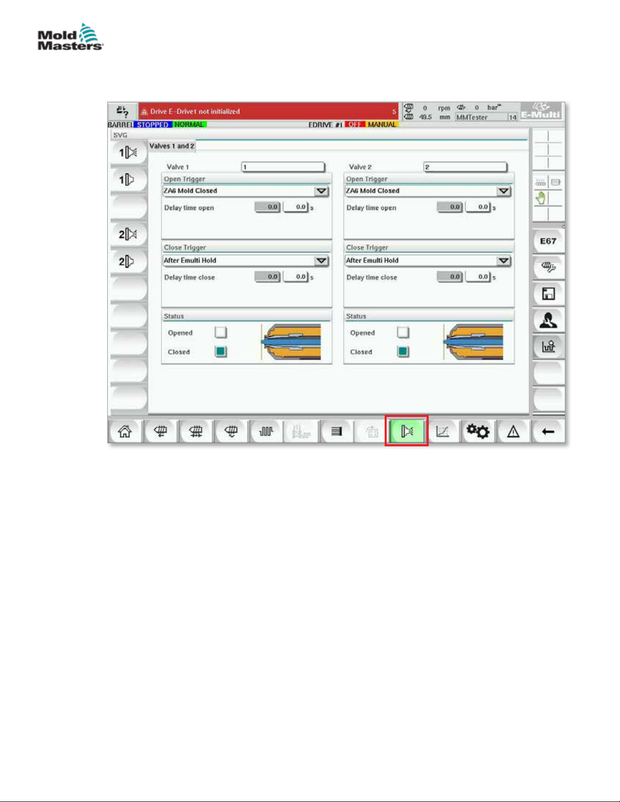
E-MULTI CONTROLLER HMI INTERFACE
7.15 Valve Gate Settings Screen
This screen is used to control individual valve gates, typically for single acting
solenoids in pneumatic or hydraulic systems.
7-43
Figure 7-16 Valve gate settings screen
© 2020 Mold-Masters (2007) Limited. All Rights Reserved.
E-Multi Controller User Manual
Page 97
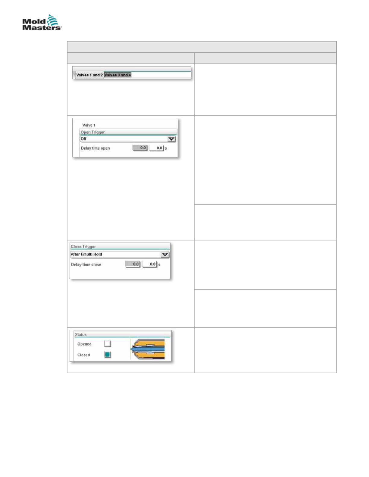
E-MULTI CONTROLLER HMI INTERFACE
Valve Gate Settings Screen - continued
Table 7-26 Valve Gate Settings Screen Elements
Screen Components Description
Top Tabs
The tabs at the top of the screen take the user
to the settings for two valve gates at a time (e.g.
Valves 1 and 2; Valves 3 and 4).
For each valve gate the user can set the Open and
Close triggers and timing.
Open Trigger
Drop down options:
O
MoldClosing
ZA6 Mold Closed - signal
ZB3 Eject 1 Bwd- signal (ejection)
ZB4 Eject 1 Fwd- signal (ejection)
ZB5 Core 1 Pos 1- signal (robot)
ZB5 Core 1 Pos 2- signal (robot)
ZB5 Core 2 Pos 1- signal (robot)
ZB5 Core 2 Pos 2- signal (robot)
7-44
Delay time open
In addition to the open trigger, a delay time in
seconds may be added to ne tune the valve
movement relative to the trigger signal.
Close Trigger
Drop down options:
After E-Multi Hold
After E-Multi Decompression
After E-Multi Plasticize
Delay time close
In addition to the close trigger, a delay time in
seconds may be added to ne tune the valve
movement relative to the trigger signal.
Current Status
A green indicator box shows whether the valve
gate is currently open or closed.
E-Multi Controller User Manual
© 2020 Mold-Masters (2007) Limited. All Rights Reserved.
Page 98
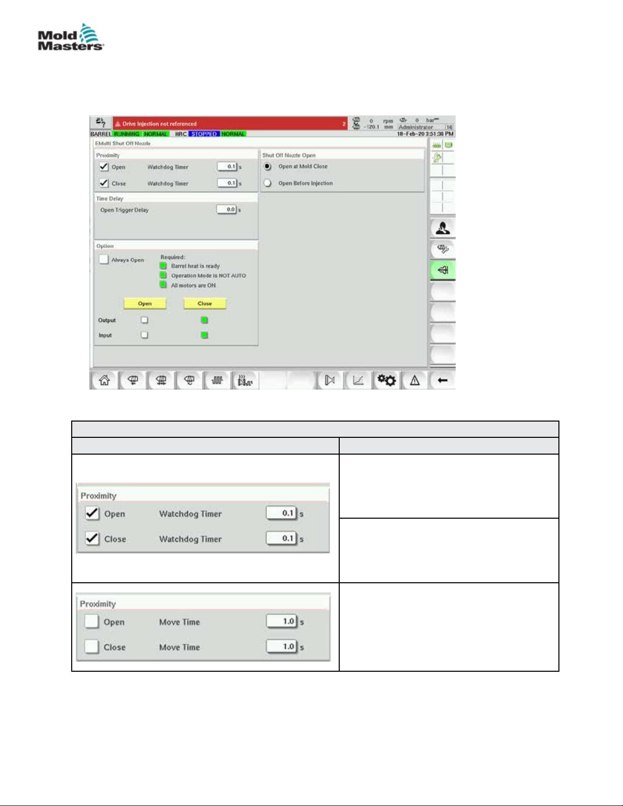
E-MULTI CONTROLLER HMI INTERFACE
7.16 Shutoff-Nozzle Settings Screen
The shuto-nozzle settings screen is used to congure an optional shuto nozzle:
7-45
Table 7-27 Screen Elements of Shuto-Nozzle Settings
Screen Element Descripon
Proximity
When the open or close boxes are checked,
the shuto nozzle has sensors to indicate that
the nozzle is in the open or closed position.
Watchdog Timer
When sensors are present, the watchdog
timers set the maximum time for the shuto to
change state after the trigger is received.
Move Time
When sensors are not present, the watchdog
timers change to move timers. These timers
add a delay to the process to allow the shuto
nozzle to open or close before the process
continues.
© 2020 Mold-Masters (2007) Limited. All Rights Reserved.
E-Multi Controller User Manual
Page 99
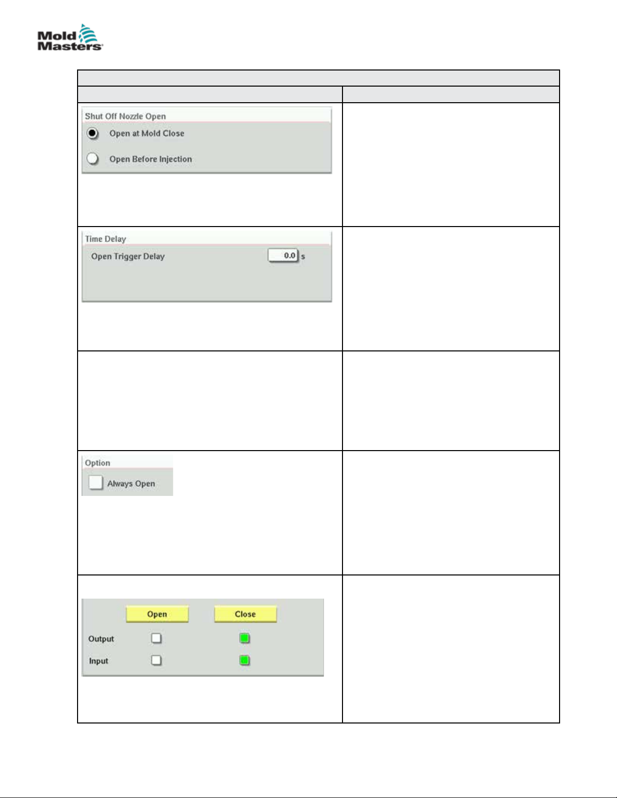
E-MULTI CONTROLLER HMI INTERFACE
Table 7-27 Screen Elements of Shuto-Nozzle Settings
Screen Element Descripon
Shut O Nozzle Open
Selects the open trigger for the shuto nozzle.
Mold Close—The shuto nozzle opens when
the Mold Close (A6) signal from the IMM turns
on.
Before Injection—The shuto opens when
the injection trigger specied on the E67
settings page turns on.
Time Delay
Adds a delay of the specied time after the
open trigger turns on.
The delay is only active if the open trigger is
Mold Closed and the injection trigger is not
Mold Closed.
7-46
Delay time is ignored if the shuto nozzle is
set to Always Open.
Close Trigger
The shuto nozzle closes automatically
after pre-decompression (also known as
decompression before plasticize) completes.
If a recovery delay is set on the recovery
settings page, the shuto nozzle will close
after the recovery delay has elapsed.
Option—Always Open
The shuto nozzle may be set to always be
open for testing or in case where the process
does not require the shuto nozzle to be
closed.
The nozzle will stay open except when the
safety gate is opened, an emergency stop
condition is present, or the system is turned
o.
Manual Operation
Tapping the Open or Close buttons will open
or close the shuto nozzle if the movement
conditions are met.
E-Multi Controller User Manual
With Sensors
The Output indicators show the status of the
PLC outputs to the hydraulic or pneumatic
valve.
The Input indicators show the status of the
sensors.
© 2020 Mold-Masters (2007) Limited. All Rights Reserved.
Page 100
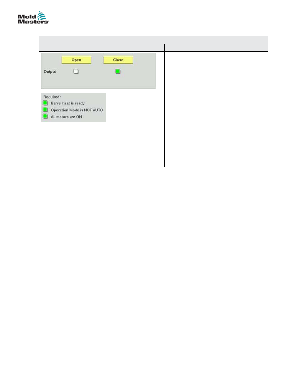
E-MULTI CONTROLLER HMI INTERFACE
Table 7-27 Screen Elements of Shuto-Nozzle Settings
Screen Element Descripon
Without Sensors
Only the Output indicators are shown.
Movement Conditions
The shuto nozzle will only operate if certain
conditions are met.
The barrel heats must be up to temperature
and auto-soak completed successfully or the
soak timer must be nished.
The shuto nozzle cannot be operated
manually when the system is in automatic
mode.
7-47
The servo motors must be on (F10 LED on).
© 2020 Mold-Masters (2007) Limited. All Rights Reserved.
E-Multi Controller User Manual
 Loading...