

Page 1

HBAnyware
Last Updated January 25, 2008
®
Version 3.4
User Manual
Utility
Page 2

Copyright© 2008 Emulex Corporation. All rights reserved worldwide. No part of this document may be reproduced
by any means nor translated to any electronic medium without the written consent of Emulex Corporation.
Information furnished by Emulex Corporation is believed to be accurate and reliable. However, no responsibility is
assumed by Emulex Corporation for its use; or for any infringements of patents or other rights of third parties which
may result from its use. No license is granted by implication or otherwise under any patent or patent rights of Emulex
Corporation.
Emulex, AutoPilot Installer, BlockGuard, cLAN, FabricStream, FibreSpy , Giganet, HBAnyware, InSpeed, IntraLink,
LightPulse, MultiPulse, SAN Insite, SBOD and Vixel are registered trademarks, and AutoPilot Manager, EZPilot,
SLI and VMPilot are trademarks of Emulex Corporation. All other brand or product names referenced herein are
trademarks or registered trademarks of their respective companies or organizations.
Emulex provides this manual "as is" without any warranty of any kind, either expressed or implied, including but not
limited to the implied warranties of merchantability or fitness for a particular purpose. Emulex Corporatio n may
make improvements and changes to the product described in this manual at any time and without any notice. Emulex
Corporation assumes no responsibility for its use, nor for any infringements of patents or other rights of third parties
that may result. Periodic changes are made to information contained herein; although these changes will be
incorporated into new editions of this manual, Emulex Corporation disclaims any undertaking to give notice of such
changes.
The HBAnyware Utility User Manual Page ii
Page 3

Introduction.............................................................................................................. 1
Known Issues.................................................................................................... 3
Installing HBAnyware Components..........................................................................4
Installing the HBAnyware Utility.........................................................................4
Installing the HBAnyware Utility with Web Launch.............................................6
Installing the HBAnyware Utility Security Configurator......................................7
Uninstalling the HBAnyware Security Configurator............................................ 8
Uninstalling HBAnyware Web Launch Only....................................................... 9
Uninstalling the Utility Package.........................................................................9
Using the HBAnyware Components....................................................................... 11
Starting the HBAnyware Utility......................................................................... 11
Starting HBAnyware with Web Launch............................................................ 11
Starting the HBAnyware Security Configurator................................................ 11
Starting HBAnyware from the Command Line................................................. 12
Examples of Modifications ..................................................................12
The HBAnyware Utility Window Element Definitions ....................................... 13
The Menu Bar ...........................................................................................14
The Toolbar............................................................................................... 14
The Toolbar Buttons.................................................................................. 14
Sort Toolbar Buttons........................................................................... 14
The Discovery-Tree................................................................................... 15
Discovery-Tree Icons..........................................................................15
Property Tabs............................................................................................16
Status Bar................................................................................................. 16
Changing Management Mode ......................................................................... 17
Resetting HBAs...............................................................................................18
Changing HBA Names .................................................................................... 19
Discovering HBAs ........................................................................................... 20
Automatic Fibre Channel Discovery.......................................................... 20
Remote SAN Management Using TCP/IP Access Protocol....................... 20
Adding a Single Host ..........................................................................21
Adding a Range of Hosts.................................................................... 21
Removing Hosts..................................................................................23
Configuring Discovery Settings................................................................. 23
Sorting HBA Information .................................................................................. 24
Viewing Remote and Local HBAs..............................................................24
Viewing HBA Information.................................................................................25
Viewing Discovery Information..................................................................25
Viewing Host Information ..........................................................................26
The Host Information Tab....................................................................26
The Driver Parameters Tab................................................................. 27
Viewing General HBA Attributes ............................................................... 28
Viewing Detailed HBA Information ............................................................29
Viewing Fabric Information........................................................................ 31
Viewing Target Information........................................................................ 32
Viewing LUN Information...........................................................................33
Masking and Unmasking LUNs (Windows, Solaris LPFC and
Solaris emlxs (SFS))........................................................................... 34
Viewing Port Statistics............................................................................... 35
Viewing Firmware Information...................................................................37
Viewing Target Mapping (Windows, Solaris LPFC and
Solaris emlxs (SFS))................................................................................. 38
The HBAnyware Utility User Manual Page iii
Page 4

Viewing Target Mapping (Linux)................................................................ 39
Viewing and Setting Up Authentication (Windows, Linux 8.2,
Solaris LPFC and Solaris emlxs (SFS)).............................................. 40
Viewing or Changing Authentication Configuration............................. 42
Changing Your Password.................................................................... 42
Updating Firmware..........................................................................................43
Updating Firmware (Batch Mode)..............................................................44
Enabling or Disabling an HBA’s BIOS .......................................................47
Configuring the Driver ..................................................................................... 48
Setting Driver Parameters......................................................................... 48
Restoring All Parameters to Their Earlier Values................................ 49
Resetting All Default Values ................................................................ 49
Setting an HBA Parameter Value to the Host Parameter Value.......... 50
Saving HBA Driver Parameters to a File.............................................50
Setting Driver Parameters for All HBAs in a Host ...............................50
Changing Non-dynamic Parameter Values (Linux)..............................51
Creating and Assigning a Batch Mode Driver Parameters File.................. 52
Storport Miniport Driver Parameters................................................................ 54
Driver for Solaris LPFC – Configuration File Reference ................................. 60
Driver For Solaris emlxs (SFS) Driver Parameters.......................................... 74
Solaris emlxs (SFS) and Solaris LPFC Driver Parameter Cross-Reference.... 79
Driver for Linux Parameter Tables...................................................................85
Version 8.0 LPFC and LPFCDFC Parameter............................................ 85
Version 8.2 LPFC and LPFCDFC Parameter........................................... 88
DH-CHAP Authentication and Configuration....................................... 88
Enabling Authentication...................................................................... 88
The lpfc_enable_auth Module Parameter........................................... 88
The fcauthd Daemon .......................................................................... 88
fcauth Daemon Parameters................................................................ 89
Setting Remote and Local Passwords ................................................ 89
Driver for VMware ESX Configuration Parameters..........................................92
Server Performance (Windows).......................................................................95
I/O Coalescing .......................................................................................... 95
Performance Testing................................................................................. 95
Mapping and Masking ..................................................................................... 96
Automapping SCSI Devices (Windows) .................................................... 96
Mapping and Masking Defaults (Windows) ............................................... 97
Setting Up Persistent Binding (Windows, Solaris LPFC and
Solaris emlxs (SFS))................................................................................. 97
Adding New Targets Using sd.conf for Solaris 8................................. 99
HBAnyware Security............................................................................................100
Introduction ................................................................................................... 100
Creating the Access Control Group............................................................... 100
Designating a Master Security Client.............................................................101
Access Control Groups..................................................................................101
Introduction............................................................................................. 101
Access Control Group Tab on the MSC................................................... 102
Access Control Group Tab on a Non-MSC.............................................. 103
ACG Icons............................................................................................... 103
Adding a Server to the ACG .................................................................... 104
Deleting a Server from the ACG.............................................................. 104
Removing Security from all Servers in the ACG...................................... 104
Generating New Security Keys ............................................................... 104
The HBAnyware Utility User Manual Page iv
Page 5

Restoring the ACG to Its Last Saved Configuration ................................ 105
Accessing a Switch................................................................................. 105
Access Sub-Groups.......................................................................................105
Introduction............................................................................................. 105
ASG Icons............................................................................................... 106
Creating an ASG..................................................................................... 106
Reserved Indices - Examples.................................................................. 107
Adding a Server to an ASG..................................................................... 108
Deleting an ASG ..................................................................................... 108
Restoring an ASG to Its Last Saved Configuration.................................. 108
Editing an ASG .......................................................................................108
About Offline ASGs................................................................................. 110
Backup Masters..............................................................................................111
Introduction..............................................................................................111
Backup Master Eligible Systems..............................................................111
Backup Master Tab and Controls ............................................................ 112
Creating a Backup Master ....................................................................... 112
Reassigning a Backup Master as the New MSC from the Old MSC........ 113
Reassigning a Backup Master as the New MSC from the
Backup Master........................................................................................ 113
Diagnostics.......................................................................................................... 115
Performing Diagnostic Tests ......................................................................... 115
Running a Quick Test.............................................................................. 116
Running a Power On Self Test (POST)................................................... 116
Using Beaconing..................................................................................... 116
Creating Diagnostic Dumps..................................................................... 117
Displaying PCI Registers and Wakeup Information................................. 118
Running Advanced Diagnostic Tests............................................................. 118
Running Loopback Tests......................................................................... 119
Running End-to-End (ECHO) Tests ......................................................... 121
Saving the Log File........................................................................................ 122
Using the HBAnyware Utility Command-Line Interface........................................ 123
Using the CLI Client ...................................................................................... 123
Syntax Rules........................................................................................... 123
Troubleshooting...................................................................................................136
General Situations.........................................................................................136
Emulex Driver for Windows and HBAnyware Situations................................ 138
Emulex Driver for Solaris LPFC and HBAnyware Situations ......................... 138
Emulex Driver for Linux and HBAnyware Situations ..................................138
Security Configurator Situations - Access Control Groups (ACG) ................. 143
Security Configuration Situations - Access Sub-Groups (ASG).....................143
HBAnyware Security Configurator Situations - Backup Masters.................... 145
Error Message Situations.............................................................................. 146
Master Security Client Situations................................................................... 147
Non-Hierarchical and Hierarchical ASG ........................................................ 148
The HBAnyware Utility User Manual Page v
Page 6

Introduction
Emulex® drivers have many properties that you can modify using the HBAnyware® configuration utility.
The utility is client/server based and provides 'remote' configuration capability to other host platforms
running the utility. This remote configuration capability can be provided by either Fibre Channel (FC)
access (host systems on the same FC Storage Area Network (SAN) or by Transmission Control
Protocol/Internet Protocol (TCP/IP) access (from IP addresses of remote machines). The HBAnyware
utility also enables local discovery of Emulex and OEM branded Emulex host bus adapters (HBAs).
This manual supports the following versions of the HBAnyware application.
• Windows
• Solaris LPFC
• Solaris emlxs (SFS)
• Linux
• VMware ESX Server
• Use the HBAnyware utility to do any of the following (see Table 1 to determine if a sp ecific
feature or task is supported by your operating system):
• Discover local and remote hosts, HBAs, targets and Logical Unit Numbers (LUNs)
• Enable local and FC discovery of Emulex and OEM branded Emulex HBAs
• Reset HBAs
• Set up persistent binding
• Set HBA driver parameters simultaneously to multiple HBAs using Batch Update
• Set global driver parameters to HBAs
• Update firmware and FC boot code (x86 BootBIOS, OpenBoot or EFIBoot) on a single
HBA or multiple HBAs using Batch Update
• Enable or disable the x86 BootBIOS
• Run diagnostic tests on HBAs
• Manage local, FC remote and TCP/IP accessed HBAs
• Locate HBAs using beaconing
• Mask and unmask LUNS
• Perform authentication using the Fibre Channel Security Protocol Diffie-Hellman Challenge Handshake Authentication Protocol (FC-SP DH-CHAP)
The HBAnyware Utility User Manual Page 1
Page 7

Table 1: HBAnyware Features and Tasks Cross-Reference
Feature/Task Windows
HBAnyware Graphical User
Interface (GUI)
HBAnyware Command Line
Interface (CLI)
HBAnyware with Web Launch
utility
HBAnyware Security
Configurator
Discover local hosts, HBAs,
targets and LUNs
Discover remote hosts, HBAs,
targets and LUNs
Enable local discovery of
Emulex and OEM branded
Emulex HBAs
Enable FC discovery of
Emulex and OEM branded
Emulex HBAs
Reset HBAs
Set up persistent binding
Set HBA driver parameters
simultaneously to multiple
HBAs using Batch Update
Set global driver parameters to
HBAs
Update firmware and FC boot
code on a single HBA or
multiple HBAs using Batch
Update
Enable or disable the x86
BootBIOS
Run diagnostic tests on HBAs
Manage local HBAs
Manage FC remote and
TCP/IP accessed HBAs
Locate HBAs using beaconing
Mask and unmask LUNS
Perform authentication using
FC-SP DH-CHAP
XXXX
XXXXX
XXXX
XXXX
XXXXX*
XXXXX*
XXXXX*
XXXXX*
XXXXX*
XXX
XXXX
XXXXX**
XXXXX*
XXXXX*
XXXX
XXXXX*
XXXXX*
XXXXX
XXX
XXXX
Solaris
LPFC
Solaris
(emlxs) SFS
Linux
VMware ESX
Server
* Supported by only hbacmd on VMware ESX Server. Remote management clients can perform these func-
tions on ESX Server HBAs using the HBAnyware GUI.
** Temporary (not persistent) driver parameters are supported only by hbacmd on VMware ESX Server.
The HBAnyware Utility User Manual Page 2
Page 8

Known Issues
The following issues have been reported at the time of publication. These issue s may not have been
verified or confirmed and may apply to another product, such as hardware.
• Emulex provides support for LightPulse
Names (WWPNs) outside the typical Emulex range, such as Hewlett-Packard’s upcoming Virtual
Connect for FC on the BladeSystem c-Class platform. In these environments, HBAnyware utility
version 3.2 or later must be deployed across all servers on the SAN, and on any o ther
management console used for TCP/IP access management.
• If there are multiple versions of the Java Runtime Environment (JRE) installed on your Internet
Explorer client, then you may see the following text in the browser's main display window when
you attempt to launch the HBAnyware utility via the browser:
Emulex Corporation HBAnyware Demo of HBAnyware WebStart web
n.n.n.n.....
If you verified that the HBAnyware Web Launch Services package is installed and is running on
the target server, try one of these two workarounds:
• Exit the browser, then restart it. The HBAnyware utility launches successfully.
• Uninstall all non-essential versions of the JRE. HBAnyware Web Launch services
require only a single version of the JRE be installed on the Windows browser client.
• On the VMware ESX Server, there is a known issue with the discovery-threads parameter. The
range for this parameter should be 30 - 64 (decimal). The default is erroneously set to 1. Set this
driver parameter to a valid value. If you do not, when you change any driver parameter value,
the following error message may be displayed: “Driver Parameter ‘discovery-threads’ is not
within the allowed range”.
• Centraliz ed management of HBAs acros s VMware ESX servers must be limi ted to, at most, one
HBAnyware client. This limitation applies to HBAnyware remote con nectivity for both FC (inband) and TCP/IP (out-of-band) management. The remote HBAnyware client configuration must
be modified to disable automatic periodic polling of remote servers.
To disable automatic periodic polling of remote servers:
®
HBAs that are reprogrammed with World Wide Port
1. Start the HBAnyware utility.
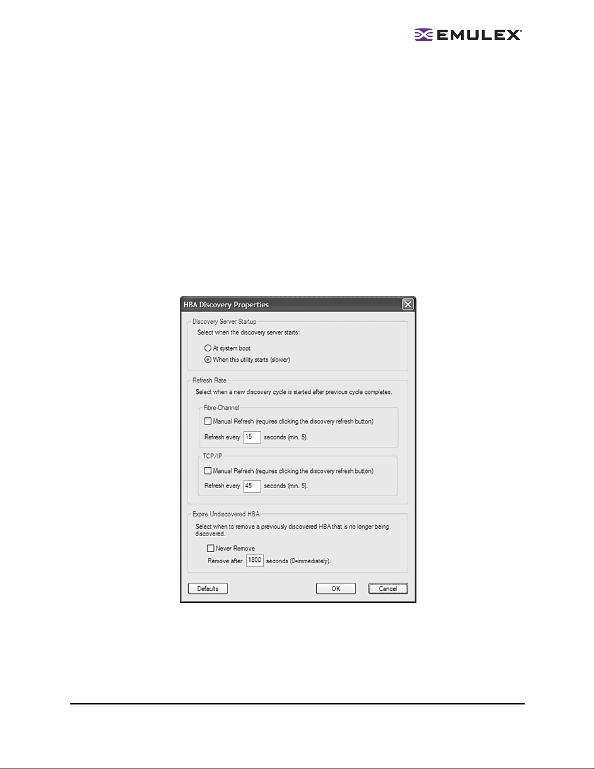
2. From the Menu bar, click Discovery>Modify Settings. The HBA Discovery Properties dialog box appears.
3. Define the discovery properties as follows:
• Discovery Server Startup area: This setting defaults to When the utility starts.
Keep this default or if necessary select it.
• Refresh Rate, Fibre Channel area: Select the Manual Refresh (requires click-
ing the discovery refresh button) checkbox.
• Refresh Rate, TCP/IP area: Select the Manual Refresh (requires clicking the
discovery refresh button) checkbox.
• Expire Undiscovered HBA area: Select the Never Remove checkbox.
4. Click OK.
Emulex recommends that remote management of other Windows, Linux and Solaris servers
take place in an environment separate from management of ESX servers. For example, other
servers should exist in a separate zone so that the HBAnyware client that manage them does
not automatically discover ESX servers.
The HBAnyware Utility User Manual Page 3
Page 9

Installing HBAnyware Components
Installing the HBAnyware Utility
In Windows:
The AutoPilot Installer
the Quick Installation Manual for more information. This ma nual is available on the Emulex Web site for
your driver version.
In Solaris LPFC, Solaris emlxs (SFS) and Linux:
The following must be installed before you can install the utilities:
• The appropriate driver for your operating system:
• Solaris LPFC driver version 6.20i or later.
• Solaris emlxs (SFS) driver version 2.21 or later
• Linux driver version 8.0.16.34 or later.
• Emulex Driver for VMware ESX, version 7.4 or later . See the Emulex Driver for VMware ESX
User Manual for specific information on driver support in ESX Releases.
• For Solaris LPFC and Solaris emlxs (SFS), JRE 5.0; HBAnyware utilities will not run under
earlier versions of the JRE. The JRE and instructions for installation are available at
http://java.sun.com/downloads/index.html.
Caution: The utilities require java runtime binaries and libraries, their path must be included at
®
software streamlines the Emulex driver and HBAnyware utility installation. See
the beginning of the PATH environment variable to avoid conflict s with earlier versions
of java that may still be installed on the system. For example, if the java runtime
binaries are in /usr/java/bin, then include this path in the PATH environment variable.
For example: (bash> export PATH="/usr/java/bin:$PATH")
• For Solaris emlxs (SFS), the Emulex Fibre Channel Adapter (FCA) utilities; See the FCA Utilities
User Manual for instructions on unpacking and installing the FCA Utilities.
• In Linux, previous versions of the application helper module must be uninstalled. You must run
the uninstall script that shipped with the version of the application helper module you want to
remove.
To install the HBAnyware utilities in Solaris LPFC and Solaris emlxs (SFS):
1. Uncompress and untar the EmlxApps file included in the driver package. For Solaris emlxs
(SFS), proceed to step 3.
2. For Solaris LPFC, run the unpack script to obtain the correct package version. Type:
./unpack_apps
3. Unzip the file. Type:
gunzip HBAnyware-<version>-<platform>.tar.gz
4. Untar the file. Type:
tar -xvf HBAnyware-<version>-<platform>.tar
5. Run the pkgadd utility. Type:
pkgadd -d .
6. When prompted by pkadd, choose to install HBAnyware.
7. When prompted by pkadd, answer the HBAnyware installation option questions.
The HBAnyware Utility User Manual Page 4
Page 10

To install the HBAnyware utilities in Linux:
Note: This procedure also installs the application helper module on your system.The
application helper module allows HBAnyware to communicate with the Emulex driver
for Linux. The 'elxlpfc' init script is also installed and configured to start and stop the
'lpfcdfc' driver during system startup and shutdown.
1. Log on as ‘root’.
2. Download the utilities from the Emulex web site or copy them to the system from the installation
CD.
3. Copy the ElxLinuxApps-<AppsRev><DriverRev>.tar file to a directory on the install machine.
4. Change (use cd command) to the directory to which you copied the tar file.
5. Untar the file. Type:
tar xvf ElxLinuxApps-<AppsRev><DriverRev>.tar
6. Uninstall any previously installed versions. Type:
./uninstall
7. Run the install script. Type:
./install
8. Enter the type of management you want to use:
1 Local Mode : HBA's on this Platform can be managed by
HBAnyware clients on this Platform Only.
2 Managed Mode: HBA's on this Platform can be managed by local
or remote HBAnyware clients.
3 Remote Mode : Same as '2' plus HBAnyware clients on this
Platform can manage local and remote HBA's.
9. You are prompted as to whether or not to allow users to change management mode after
installation. Enter 'y' for yes, or 'n' for no.
You can also install the applications kit on an upgraded kernel. The lpfc driver must be part of the target
kernel distribution and the utilities package must have been installed on the current kernel.
To install the applications kit on an upgraded kernel :
1. Boot to the new kernel.
2. Log on as ‘root’.
3. Change (use the cd command) to the directory containing the unpacked Applications Kit.
4. Run the install upgrade kernel script. Type:
./install upgradekernel
To install the HBAnyware Agent in VMware ESX Server:
The LPFC driver must be loaded before you can install the HBAnyware Agent.
1. Log in as ‘root’.
2. Copy the <AppsRev><DriverRev>.rpm file to a directory on the install machine.
3. CD to the directory to which you copied the rpm file.
4. Install the rpm. Type:
rpm -i <AppsRev><DriverRev>.rpm
The rpm contents are installed in /opt/hbanyware. The hbacmd utility is also located in this directory.
The HBAnyware Utility User Manual Page 5
Page 11

Installing the HBAnyware Utility with Web Launch
In addition to the driver and HBAnyware utilities, the following must be installed before you can install
the Web Launch feature:
Note: The HBAnyware utility with Web Launch is not supported on the VMWare ESX
Server.
• In Windows:
• Microsoft Internet Information Services (IIS) Server must be installed. See the Microsoft
Web site for information on downloads and installation.
• JRE must be installed. See the www.java.com Web site for information on downloads and
installation.
• In Solaris LPFC, Solaris emlxs (SFS) and Linux:
• Apache must be installed and running on the server that is hosting the Web Launch Services
software.
• The Java Web Start application must be installed and running on the browser host.
The system on which you are installing the Web Launch services package (the server) requires:
• The HTTP server must be configured to handle the JNLP MIME file type. The followin g
MIME file type/file extension must be added to your server configuration:
MIME type: application/x-java-jnlp-file
File Extension: jnlp
• The HTTP server must be configured and running.
The system on which you are running the browser (the client) requires:
• JRE 5.0 or later must be installed. The HBAnyware-installed JRE must match the
HBAnyware code base. Specific requirements:
• Sun 32-bit JRE 5.0 or later for Intel based systems (x86 and IA64)
• Sun 32-bit JRE 5.0 or later x86-64
• 64-bit JRE 5.0 or later for RH4 and SL9 (ppc64)
• 32-bit JRE 5.0 or later for RH5 and SL10 (ppc64)
See the appropriate vendor documentation for detailed instructions about configuring MIME
types, configuring and starting the HTTP server and installing the JRE.
To install the HBAnyware utility with Web Launch:
In Windows:
Click Programs>Emulex >HBAnyware WebLaunch Install. Web Launch installation begins.
In Solaris LPFC, Solaris emlxs (SFS) and Linux:
1. Log on as ‘root’.
2. Navigate to the HBAnyware directory.
• Solaris LPFC and Solaris emlxs (SFS):
cd /opt/hbanyware
• Linux:
cd /usr/sbin/hbanyware
The HBAnyware Utility User Manual Page 6
Page 12

3. Run the install script. Type:
./wsinstall
4. When prompted, enter the Web server's document root directory. For example:
/srv/www/htdocs
5. You are provided with the IP address of the host and asked if that is the IP address that is being
used by your Web server. Answer Y or N as appropriate. If you answer N, you are prompted for
the IP address you wish to use.
6. You are asked if your Web server is listening on the normal default HTTP port (80)? Answer Y or
N as appropriate. If you answer N, you are prompted for the port you wish to use.
You are notified when the installation of the HBAnyware Web Launch package is complete.
Once the necessary information is entered, you are notified when the installation of the HBAny-
ware Web Launch package is complete. The Web Launch configuration files are created and
Web Launch Services automatically starts.
7. To verify installation, locate another client, open a Web browser window and enter this URL
according to this format:
http://IP_ADDR:PORT_NUM/hbanyware.jnlp
where IP_ADDR is the IP address of host on which you installed the HBAnyware Web Launch
service, and PORT_NUM is the TCP port number of the listening hosts' Web server. The standard HBAnyware user interface is displayed.
Installing the HBAnyware Utility Security Configurator
The Emulex driver and the HBAnyware utilities must be installed before you can install the HBAnyware
Security Configurator.
Note: The HBAnyware utility Security Configurator is not supported on the VMWare ESX
Server.
To install the HBAnyware utility Security Configurator:
In Windows:
1. Locate the SSCsetup.exe file. The default path for this file is:
C:\Program Files\HBAnyware
2. Double-click the SSCsetup.exe file. A welcome window appears.
3. Click Next. The Setup Status window is displayed. After setup completes, the Emulex
HBAnyware Security Setup Completed window appears.
4. Click Finish.
In Solaris LPFC and Solaris emlxs (SFS):
1. Copy the <HBAnywareSSC_version>.tar.gz file to a directory on the install machine.
2. cd to the directory to which you copied the .gz file.
3. Untar the file. Type:
gzcat <HBAnywareSSC_version>.tar.gz | tar xvf-
4. Log on as ‘root’.
5. At the shell prompt, type:
pkgadd -d `pwd`
The HBAnyware Utility User Manual Page 7
Page 13

6. When prompted by pkadd, choose to install HBAnywareSSC.
7. When prompted by pkadd, answer the HBAnyware installation option questions.
In Linux:
1. Log on as ‘root’.
2. Change (use the cd command) to the directory to which you copied the tar file. (See “Installing
the Utilities and the application helper module” on page 7 step 2 for reference.)
3. Run the install script with the ssc parameter specified. Type:
./install ssc
Uninstalling the HBAnyware Security Configurator
To uninstall the HBAnyware Security Configurator:
In Windows:
1. Select Start>Settings>Control Panel. The Control Panel appears.
2. Click Add/Remove Programs. The Add or Remove Programs window appears.
3. Select Emulex HBAnyware Security Configurator>Change/Remove.
4. Click Next. The Security Configurator is removed from the system.
5. Click Finish. Uninstallation is complete.
In Solaris LPFC and Solaris emlxs (SFS):
1. Log on as ‘root’.
Note: If the HBAnyware Security Configurator is installed, it must be uninstalled before
uninstalling the HBAnyware and driver utilities.
2. Type:
pkgrm HBAnywareSSC
In Linux:
Note: You must run the uninst all script that shipped with the ve rsion of HBAnyware Security
Configurator you want to remove. If the uninstall script resides in the usr/src directory,
be sure to copy it to a temporary directory before you run it.
1. Log on as ‘root’.
2. Change (use the cd command) to the directory to which you copied the tar file during installation.
3. Run the uninstall script with the ssc parameter specified. Type:
./uninstall ssc
The HBAnyware Utility User Manual Page 8
Page 14
Uninstalling HBAnyware Web Launch Only
To uninstall HBAnyware Web Launch, but leave the HBAnyware utility installed:
In Windows:
1. Select Start> Programs>Emulex>HBAnyware WebLaunch Uninstall. The following screen
appears:
Figure 2: HBAnyware Web Launch, Uninstallation screen
2. HBAnyware Web Launch is removed. Press any key to continue.
In Solaris LPFC, Solaris emlxs (SFS) and Linux:
1. Log on as ‘root’.
Note: If you inst alled HBAnyware with We b Launch, you must uninst all it before uni nstallin g
HBAnyware.
2. Execute the uninstallation script.
• Solaris LPFC and Solaris emlxs (SFS):
/opt/hbanyware/wsuninstall
• Linux:
/usr/sbin/hbanyware/wsuninstall
This script stops the HBAnyware Web Launch Service daemons (if they are running) and removes all
Web Launch related files from the host.
Uninstalling the Utility Package
To uninstall the HBAnyware utility and HBAnyware Web Launch:
In Windows:
1. Select St art>Settings>Control Panel. The Add/Remove Programs window appears. Select the
Install/Uninstall tab.
2. Select Emulex Fibre Channel and click Change/Remove. Click Next. The utilities are removed
from the system.
3. Click Finish. Uninstallation is complete.
In Solaris LPFC and Solaris emlxs (SFS):
1. Log on as ‘root’.
2. Type:
pkgrm HBAnyware
The HBAnyware Utility User Manual Page 9
Page 15

In Linux (also uninstalls the application helper module):
1. Log on as ‘root’.
2. Change (use the cd command) to the directory to which you copied the tar file during installation.
3. Uninstall any previously installed versions. Type:
./uninstall
In VMware ESX Server (uninstalls the HBAnyware Agent):
1. Log in as ‘root’.
2. Type:
rpm -qa | grep elx
3. Locate the <AppsRev><DriverRev>.rpm file. The .rpm contents are installed in
/usr/sbin/hbanyware. The hbacmd utility is also located in this directory.
4. Type:
rpm -e <AppsRev><DriverRev>.rpm
The HBAnyware Utility User Manual Page 10
Page 16

Using the HBAnyware Components
Note: To properly view the HBAnyware utility, ensure your system meets the following
display requirements:
For Windows systems the display resolution must be set to 800 by 600 or better.
For UNIX systems the display resolution must be set to 1024 by 768 or better.
The display must run in 256-color mode or higher. HBAnyware icons use 256 colors.
If the display is set for 16 color mode, HBAnyware icons will not be displayed.
Starting the HBAnyware Utility
To start the HBAnyware utility:
In Windows:
On the Windows desktop, select Start>All Programs>Emulex>HBAnyware. If you have a Vista
system, right-click and select Run As Administrator.
In Solaris LPFC, Solaris emlxs (SFS) and Linux:
1. Log on as ‘root’.
2. Run the script to start the HBAnyware utility.
• Solaris LPFC and Solaris emlxs (SFS):
cd /opt/hbanyware/hbanyware
• Linux:
cd /usr/sbin/hbanyware/hbanyware
Starting HBAnyware with Web Launch
After the HBAnyware Web Launch software is installed and the Web Launch server is initialized, you can
launch the HBAnyware utility directly with your Web browser.
Note: Only the HBAnyware Web Launch graphic GUI is being exported to the requesting
client. All HBA discovery and remote management operations are performed by
resources running on the remote host that served up the GUI component. Therefore,
the SAN view displayed by the GUI is not from the client running the GUI, but rather
from the host from which this GUI was retrieved.
To launch the HBAnyware utility with your Web browser:
1. Open your Web browser.
2. Enter the URL of an HBAnyware.jnlp file. Make sure that the URL specifies a remote server
which has the HBAnyware Web Launch software installed and running. For example:
http://138.239.20.30/hbanyware.jnlp
Starting the HBAnyware Security Configurator
Before starting the HBAnyware Security Configurator:
• Ensure that all of the systems that are part of, or will be part of, the security configuration are
online on the network so that they receive updates or changes made to the security
configuration.
The HBAnyware Utility User Manual Page 11
Page 17

• If you are running the HBAnyware Security Configurator with TCP/IP access, TCP/IP hosts must
be added to the discovery-tree or they will not be seen by the Security Configurator.
Note: When you install the HBAnyware utility security software on a system and run the
HBAnyware utility Security Configurator for the first time, that system becomes the
Master Security Client (MSC). For more information, see “Creating the Access
Control Group” on page 100.
To start the HBAnyware Security Configurator:
In Windows:
On the desktop, click Start>All Programs>Emulex>HBAnyware Security Configurator. The
HBAnyware Security Configurator Discovery window appears. After discovery is completed, the
HBAnyware Security Configurator appears.
In Solaris LPFC, Solaris emlxs (SFS) and Linux:
• Log on as ‘root’.
• Solaris LPFC and Solaris emlxs (SFS):
cd /opt/hbanyware/ssc
• Linux:
cd /usr/sbin/hbanyware/ssc
Starting HBAnyware from the Command Line
Not all HBAs for a specific host can run FC. Therefore, if you run with TCP/IP access, that host may
display HBAs that do not appear when running FC.
To start HBAnyware from the command line:
From the directory in which the HBAnyware utility is installed, type hbanyware and press <Enter>. This
starts the HBAnyware utility with FC access.
Note: In Solaris LPFC, Solaris emlxs (SFS) and Linux: This command is case sensitive
and must be entered in all lowercase.
• Start the HBAnyware utility with TCP/IP access by adding an argument in the form “h=<host>”.
The <host> argument may be either the IP address of the host or its system name. The call will
use a default IP port of 23333, but you can override this by optionally appending a colon (:) and
entering the IP port number.
Examples of Modifications
• ./hbanyware h=138.239.82.2
The HBAnyware utility will show HBAs in the host with the IP address 138.239.82.2.
• ./hbanyware h=Util01
The HBAnyware utility will show HBAs in the host named Util01.
• ./hbanyware h=Util01
The HBAnyware utility will show HBAs in the host named Util01.
Run this modified command line to launch the HBAnyware utility for a single, remote host in
local mode.
The HBAnyware Utility User Manual Page 12
Page 18
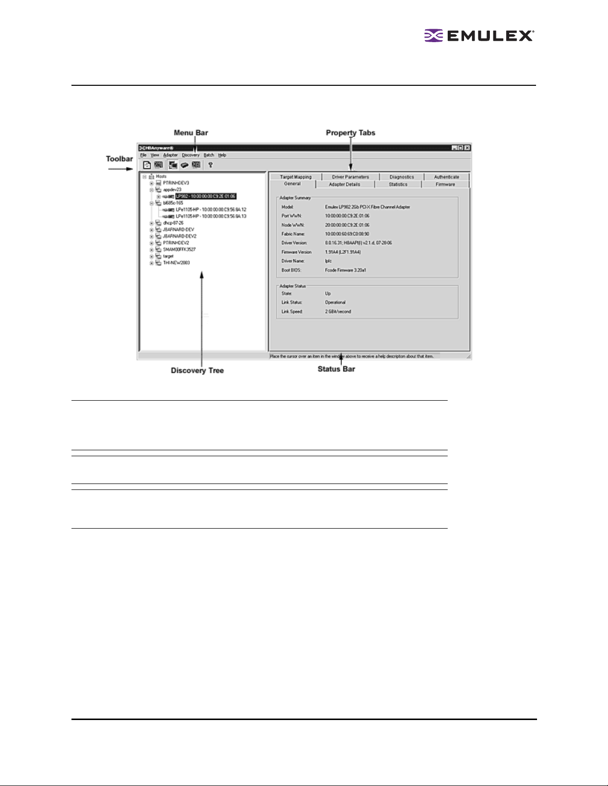
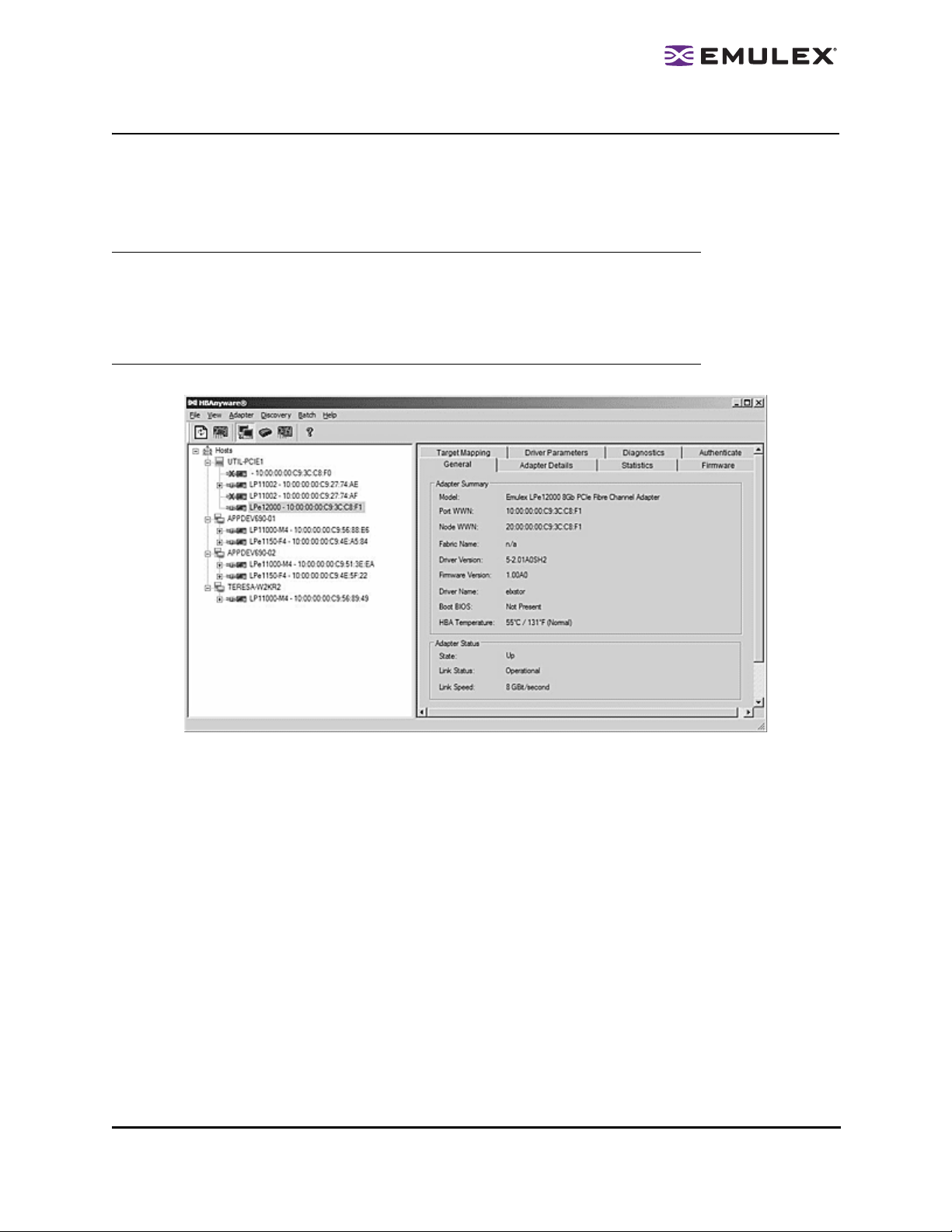
The HBAnyware Utility Window Element Definitions
The HBAnyware utility window contains five basic components: the menu bar, the toolbar, the discoverytree, the property tabs and the status bar.
Figure 3: HBAnyware Utility window
Note: The element you select in the discovery-tree determines whether a menu item or
toolbar icon is active. For example, if you select the local host or other system host,
the Reset Adapter item on the Adapter menu is unavailable. The Reset Adapter
toolbar button is unavailable as well.
Note: Screenshots in this manual are for illustrative purposes only . Your syste m information
may vary slightly.
Note: If you are using this version of the HBAnyware utility to access a remote server on
which an older version of HBAnyware is installed, features that are not available
through the server’s version of HBAnyware are grayed out.
The HBAnyware Utility User Manual Page 13
Page 19

The Menu Bar
The menu bar contains command menus that enable you to perform a variety of tasks such as exiting
the HBAnyware utility, resetting HBAs and sorting items in the discovery-tree view. Many of the menu
bar commands are also available from the toolbar.
The Toolbar
Many of the toolbar functions are also available from the menu bar. The toolbar is visible by default. Use
the Toolbar item in the View menu to hide the toolbar. If the item is checked, the toolbar is visible.
Figure 4: Toolbar
The Toolbar Buttons
The toolbar buttons perform the following tasks:
Click the Rediscover button to refresh the discovery-tree display.
Click the Reset button to reset the selected HBA.
Sort Toolbar Buttons
You can sort discovered HBAs by host name or fabric addresses. You can also choose to display only
local or remote HBAs. See page 24 for details on sort buttons.
Sort by Host Name button (default)
Sort by Fabric ID button
Local HBAs Only button
Help button
The HBAnyware Utility User Manual Page 14
Page 20
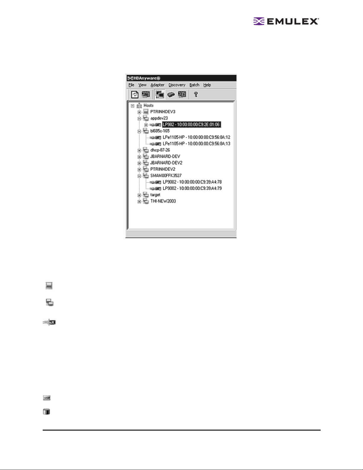
The Discovery-Tree
The discovery-tree (left pane) has icons that represent discovered network (SAN) elements (local host
name, system host names and all HBAs active on each host). Targets and LUNs are also displayed.
Figure 5: Discovery-tree
Discovery-Tree Icons
Discovery-tree icons represent the following:
This icon represents the local host.
This icon represents other hosts connected to the system.
A green HBA icon with black descriptive text represents an online HBA.
A gray HBA icon with a red X and red text represents an offline or otherwise temporarily inacces-
sible HBA. Several situations could cause the HBA to be offline or inaccessible:
• The HBA on a local host is not connected to the network, but is available for local access.
• The HBA on a local host is malfunctioning and inaccessible to the local host and the
network.
• The HBA on a local host is busy performing a local download and is temporarily inaccessible
to the local host and the network.
The Target icon represents connections to individual storage devices.
The LUN icon represents connections to individual LUNs.
The HBAnyware Utility User Manual Page 15
Page 21

The Tape LUN icon represents LUNs that are tape devices.
The Target Controller LUN icon represents LUNs that are storage controllers.
The Switch icon represents connections to the switch.
Property Tabs
The property tabs display configuration, statistical and status information for network elements. The set
of available tabs is context-sensitive, depending on the type of network element or HBA currently
selected in the discovery-tree.
Status Bar
The status bar is located near the bottom of the HBAnyware utility window. The status bar displays
messages about certain HBAnyware utility functions, such as “Discovery in process”.
The status bar is visible by default. Use the Status Bar item in the View menu to hide the status bar. If
checked, the status bar is visible.
The HBAnyware Utility User Manual Page 16
Page 22
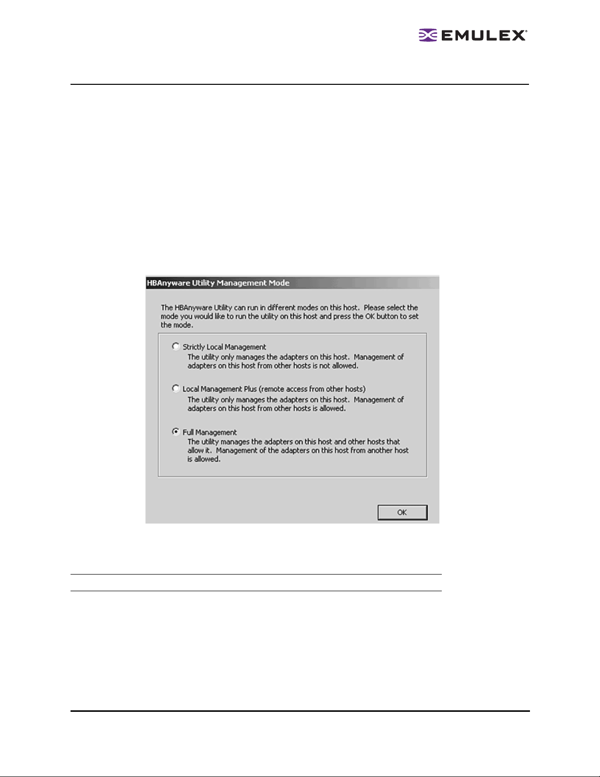
Changing Management Mode
During installation you selected a management mode, however you can chang e it if you enab led that
option during installation. The HBAnyware utility enables you to choose three types of host/HBA
management:
• Strictly Local Management - This setting only allows management of HBAs on this host.
Management of HBAs on this host from other hosts is not allowed.
• Local Management Plus - This setting only allows management of HBAs on this host, but
management of HBAs on this host from another host is possible.
• Full Management - This setting enables you to manage HBAs on this host and other hosts that
allow it.
To change HBAnyware management mode using the Management Mode dialog box:
In Windows:
1. From the File menu, select Management Mode. Th e Manage ment Mod e dialog box appears.
Figure 6: Management Mode dialog box
2. Choose the management type you want.
3. Click OK.
Note: The HBAnyware utility must be restarted to see the new management mode.
In Solaris LPFC, Solaris emlxs (SFS) and Linux:
1. Run the script to change the management mode.
• Solaris LPFC and Solaris emlxs (SFS):
cd /opt/hbanyware/set_operating_mode
• Linux:
cd /usr/sbin/hbanyware/set_operating_mode
2. Choose the management type you want.
The HBAnyware Utility User Manual Page 17
Page 23
Resetting HBAs
You can reset remote and local HBAs.
Caution: Do not reset your HBA while copying or writing files. This could result in data loss or
corruption.
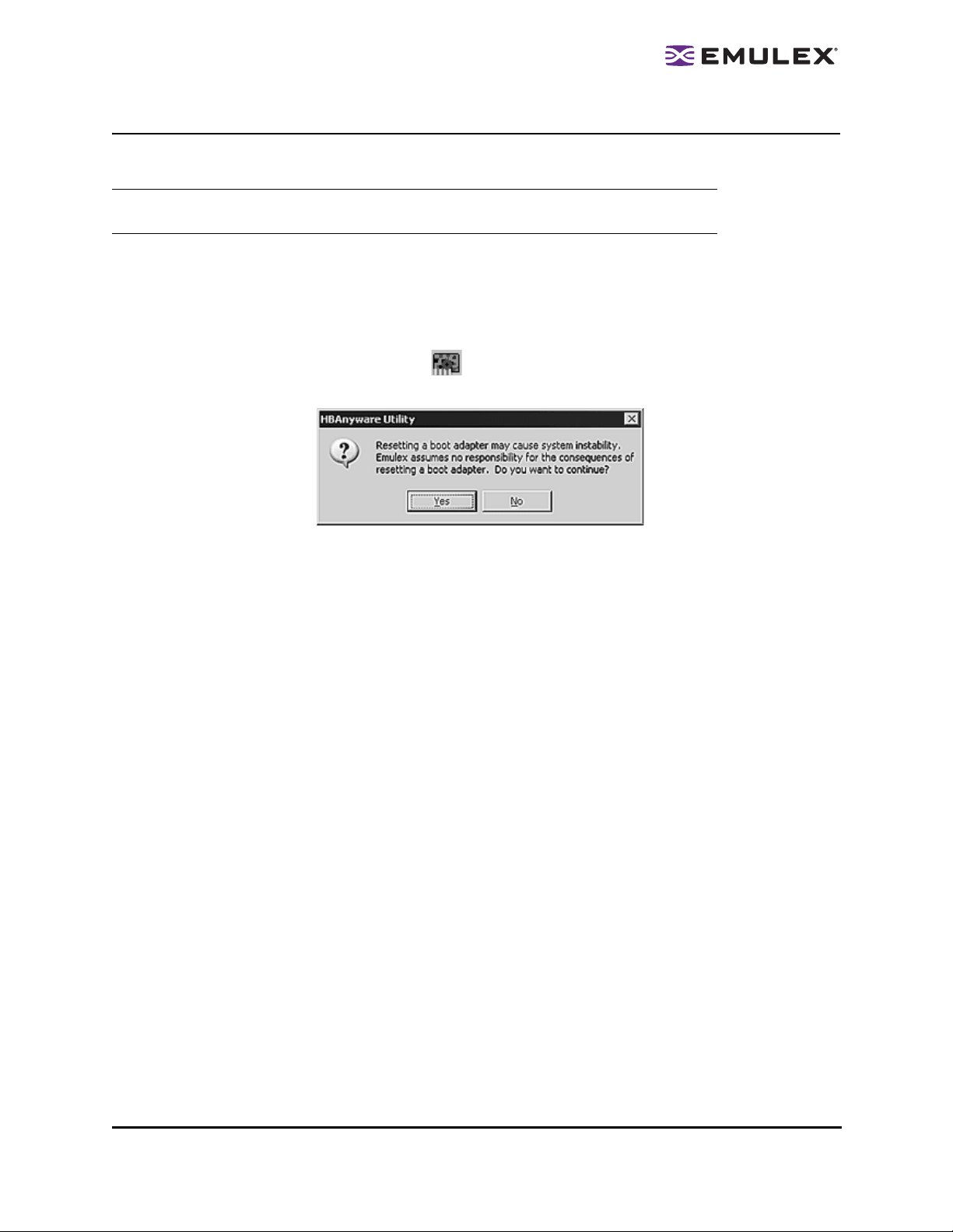
To reset the HBA:
1. In the discovery-tree, select the HBA you want to reset.
2. Do one of the following:
• From the menu bar, click Adapter, and then click Reset Adapter.
• Click the Reset HBA button: .
The following warning appears:
Figure 7: Reset Warning
3. Click Yes. The HBA resets.
The reset may require several seconds to complete. While the HBA is resetting, the status bar
shows “Reset in progress.” When the reset is finished, the status bar shows “Ready”.
The HBAnyware Utility User Manual Page 18
Page 24
Changing HBA Names
The HBAnyware utility enables you to change HBA names. For example, you may want to identify a
particular HBA with the function it supports, such as a tape drive, scanner, or some other device.
Use any characters you want for names, and names can be up to 255 characters in length. You may
also revert to the HBA's default name if you wish.
Note: Although you can change the HBA's displayed name from the default WWPN, the
change occurs in the discovery-tree only. The WWPN is still active, it is simply
replaced for display purposes with the name you enter . For example, the Port WWPN
field of the General tab is not changed. Also, any change you make to the HBA
names in your discovery-tree will be seen only by you; people running the
HBAnyware utility on another host will not see your name changes
Figure 8: General tab
To change the name of an HBA:
1. From the discovery-tree, select the HBA whose name you wish to change.
2. Do one of the following:
• Select Edit Name from the Adapter menu.
• From the discovery-tree, right-click the HBA whose name you wish to change and select
Edit Name (or Change Name).
3. Edit the HBA name in the discovery-tree.
To use the HBA's default name:
1. From the discovery-tree, select the HBA whose name you wish to change.
2. Do one of the following:
• Select Use Default Name from the Adapter menu.
• From the discovery-tree, right-click the HBA whose name you wish to change and select
Use Default Name (or Restore Default Name).
The HBAnyware Utility User Manual Page 19
Page 25
Discovering HBAs
Automatic Fibre Channel Discovery
HBAs that have a physical FC connection to the same SAN are discovered automatically when
HBAnyware is launched. HBAs that don't have a physical FC conne ctio n to the SAN whe re HBAnywar e
is launched can be discovered by sending management requests to a remote host using TCP/IP.
Note: The HBAnyware utility can only discover and manage remote HBAs on hosts running
the HBAnyware utility’s remote management server. Remote FC capabilities of the
HBAnyware utility are subject to fabric zoning and whether HBAnyware security is
being utilized. Hosts you want to discover and manage using the HBAnyware utility
must be in the same zone or discovered and managed through TCP/IP access.
Note: After adding an HBA to a running system (commonly called a hot plug), click
Discovery Refresh ( ) or restart the HBAnyware utility to display the new HBA in
the discovery-tree.
Figure 9: Discovery Information
Remote SAN Management Using TCP/IP Access Protocol
You can discover HBAs on TCP/IP hosts. Remote SAN management over TCP/IP sends remote
management requests on another LAN using TCP/IP access protocol to remote hosts. TCP/IP access
enables you to access HBAs via their host IP-address or by the name of the host on which they reside.
Since HBAs may exist on a host but not be a part of a FC network, they will not appear during normal FC
discovery. Thus, TCP/IP access enlarges the number of HBAs that can be querie d or modifie d.
Note: In Windows, if yo u are running a firewall you may need to add the HBAnyware remote
server to the firewall’s exception list. This remote server’s path is:
\Program Files\Emulex\Util\Common\rmserver.exe
The HBAnyware Utility User Manual Page 20
Page 26
The principle differences between FC and TCP/IP access are:
• A TCP/IP host with an HBA inst alled does not need to connect to a fabric to manage other hosts.
• A TCP/IP management host can manage all of the HBAs in a remote host, not just the ones
connected to the same fabric. FC can only manage HBAs connected to the same fabric.
• You can manage many more hosts since TCP/IP access is not constrained by the boundaries of
a fabric or zoning.
• True board status (e.g. link down) is available since the FC path is not necessary to send a
status request to the remote host.
• HBA security in a TCP/IP environment is much more important since many more hosts are
available for management and TCP/IP access is not affected by fabrics or zoning.
• Discovery of hosts in a TCP/IP environment is not automatic like FC discovery.
Adding a Single Host
The HBAnyware utility enables you to specify a single TCP/IP host to manage. If the host is successfully
discovered, it is added to the static list of hosts. If it has not been discovered over FC, the host and its
HBAs are added to the discovery-tree.
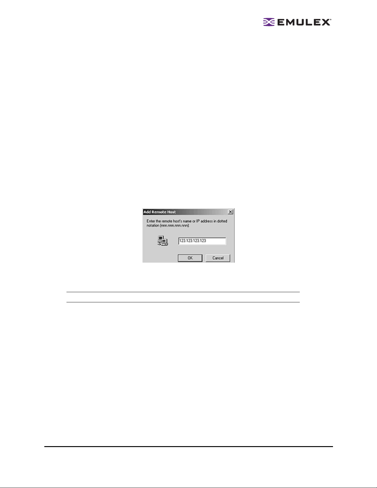
To add a single host:
1. From the Discovery menu, select TCP/IP>Add Host. The Add Remote Host dialog box appears.
Figure 10: Add Remote Host dialog box
2. Enter the name or the IP address of the host to be added. Entering the IP address is the best
way to add a new host.
Note: Using the IP address to identify the host avoids name resolution issues.
3. Click OK. You will receive a message indicating if the new host was successfully added.
Adding a Range of Hosts
You can find the TCP/IP accessed manageable hosts by searching a range of IP addresses using the
Add Range of IP Hosts dialog box. The Add Range of IP Hosts dialog box enables you to build the initial
list of TCP/IP accessed manageable hosts.
The HBAnyware Utility User Manual Page 21
Page 27
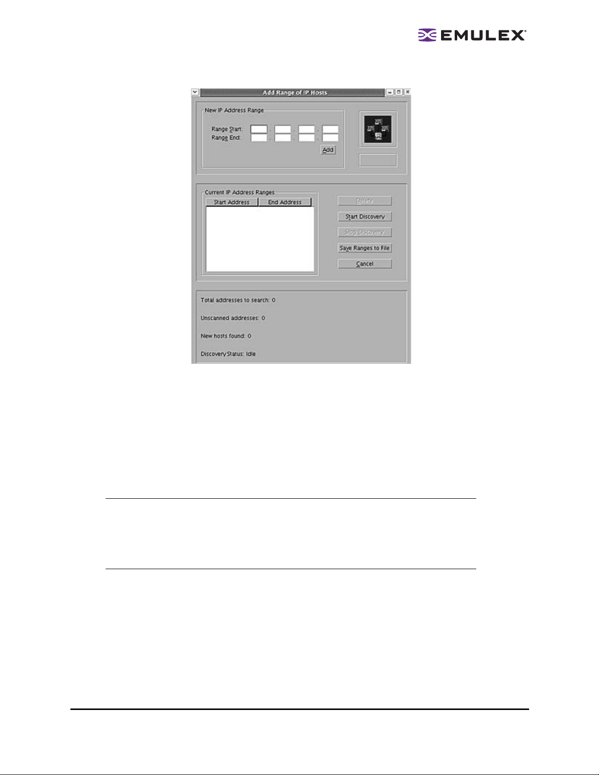
Figure 11: Add Range of IP Hosts dialog box
To add a range of hosts:
1. From the Discovery menu, select TCP/IP>Add Range of Hosts. The Add Range of IP Hosts
dialog box appears.
2. Enter the complete start and end address range and click Add. The added address range
appears in the dialog box. Add any additional ranges you wish to search.
3. Click Start Discovery. The utility checks each address in the range to determine if the host is
available and remotely manageable. The number of addr esses discovered (of m anagea ble
hosts) is periodically updated on the dialog box.
Note: The number of addresses doe s not correspond directly to the number of hosts added
to the discovery-tree. For example, some of the addresses discovered may be for
hosts that have already been discovered over FC. However, new HBAs may be
discovered on those hosts that were not discovered over FC. Also, a host may have
more than one HBA installed and both IP addresses for that host are discovered
during the search, but only one host will possibly be added to the discovery-tree.
4. Save the IP ranges:
• In Windows: A dialog box appears asking you to save the IP ranges you searched. Click Yes
to save the address ranges. If you save the address ranges, these address ranges will
appear the next time you use the Add Range of IP Hosts dialog box. Click No if you do not
want to save the address ranges.
• In Solaris LPFC, Solaris emlxs (SFS) and Linux: Click Save Ranges to File to save the
specified range(s) to a file so that these address ranges will appear the next time you use
the Add Range of IP Hosts dialog box.
The HBAnyware Utility User Manual Page 22
Page 28
Removing Hosts
Removing hosts that can no longer be discovered improves the operation of the discovery server. For
example, you may want to remove a host when it is removed from the network or detect hosts that are
no longer being discovered.
To remove hosts:
1. From the Discovery menu, select TCP/IP>Remove Host(s). The Remove TCP/IP Hosts dialog
box shows a list of discovered hosts. Any host not currently discovered appears in red. Click
Show Undiscovered Hosts Only to only display currently undiscovered hosts.
2. From the Remove TCP/IP Hosts dialog box, select the hosts you wish to remove. You can select
all the displayed hosts by clicking Select All.
3. Click OK (or Remove) to remove the selected hosts.
Configuring Discovery Settings
Use the HBAnyware Discovery Settings dialog box to configure several discovery server parameters.
You can define when to start the discovery server, when to refresh FC and TCP/IP accessed discoveries
and when to remove previously discovered HBAs that are no longer being d iscovered.
Figure 12: HBA Discovery Properties dialog box
To configure discovery settings:
1. From the Menu bar, select Discovery/Modify Settings. The HBA Discovery Properties dialog
box appears.
2. Define the discovery properties you wish and click OK. Click Defaults to return the discovery
properties to their default settings.
The HBAnyware Utility User Manual Page 23
Page 29

Sorting HBA Information
Y ou can so rt discovered HBAs by host name, fabric ID, HBA name, t arget name and LUN n umber . You can
also view local or remote HBAs. By default, both local and remote HBAs are sorted by host name.
To sort HBAs, switch between host name or fabric ID in one of two ways:
• From the menu bar: click View, then click Sort by Host Name or Sort by Fabric ID.
• From the toolbar, click one of the following button s:
• Sort HBAs by Host Name (default) .
• Sort HBAs by Fabric ID .
The HBAnyware utility sorts in ascending order. The sort recognizes letters, numbers, spaces
and punctuation marks.
Sort by Host Name
• Initially sorts by host name. Y ou cannot change host names using the HBAnyware utility;
names must be changed locally on that system.
• Within each host system, sorts by HBA model.
• If multiple HBAs have the same model number, sorts models by World Wide Node Name
(WWNN).
• If targets are present, sorts by WWPN. Multiple HBAs may refer to the same target.
• If LUNs are present, sorts by LUN number.
Sort by Fabric ID
• Initially sorts by fabric ID.
• Within each fabric ID, sorts by HBA model.
• If multiple HBAs have the same model number, sorts models by WWNN.
• If targets are present, sorts by WWPN. Multiple HBAs may refer to the same target.
• If LUNs are present, sorts by LUN number.
• If the fabric ID is all zeros, no fabric is attached.
Viewing Remote and Local HBAs
The Local HBAs Only menu item and button both work with the Sort by Host Name and Sort by Fabric ID
buttons. The first time you select this menu item or click this button, only local HBAs are displayed. To
change the view back to remote HBAs, select the menu item or click the Local HBAs Only button again.
Toggle between remote and local HBA views in one of two ways:
• From the menu bar: click View, then click Local HBAs Only.
• From the toolbar, click the Local HBAs Only button: .
The HBAnyware Utility User Manual Page 24
Page 30
Viewing HBA Information
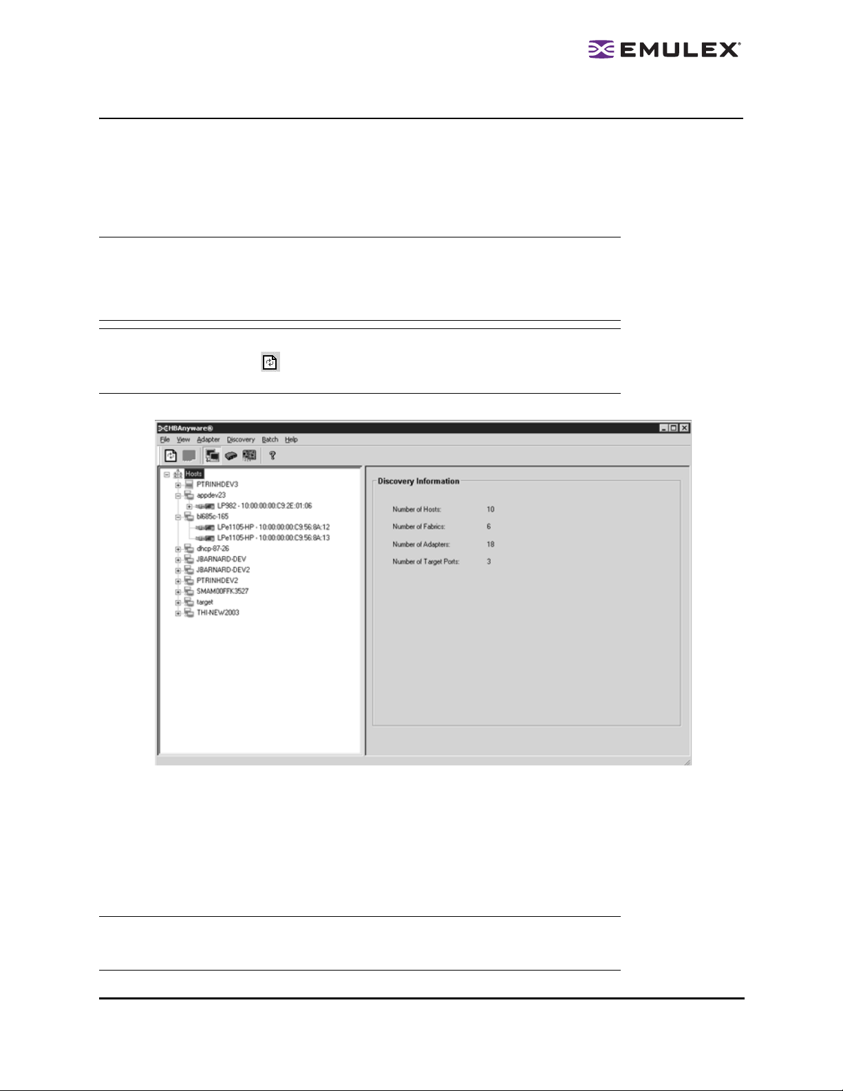
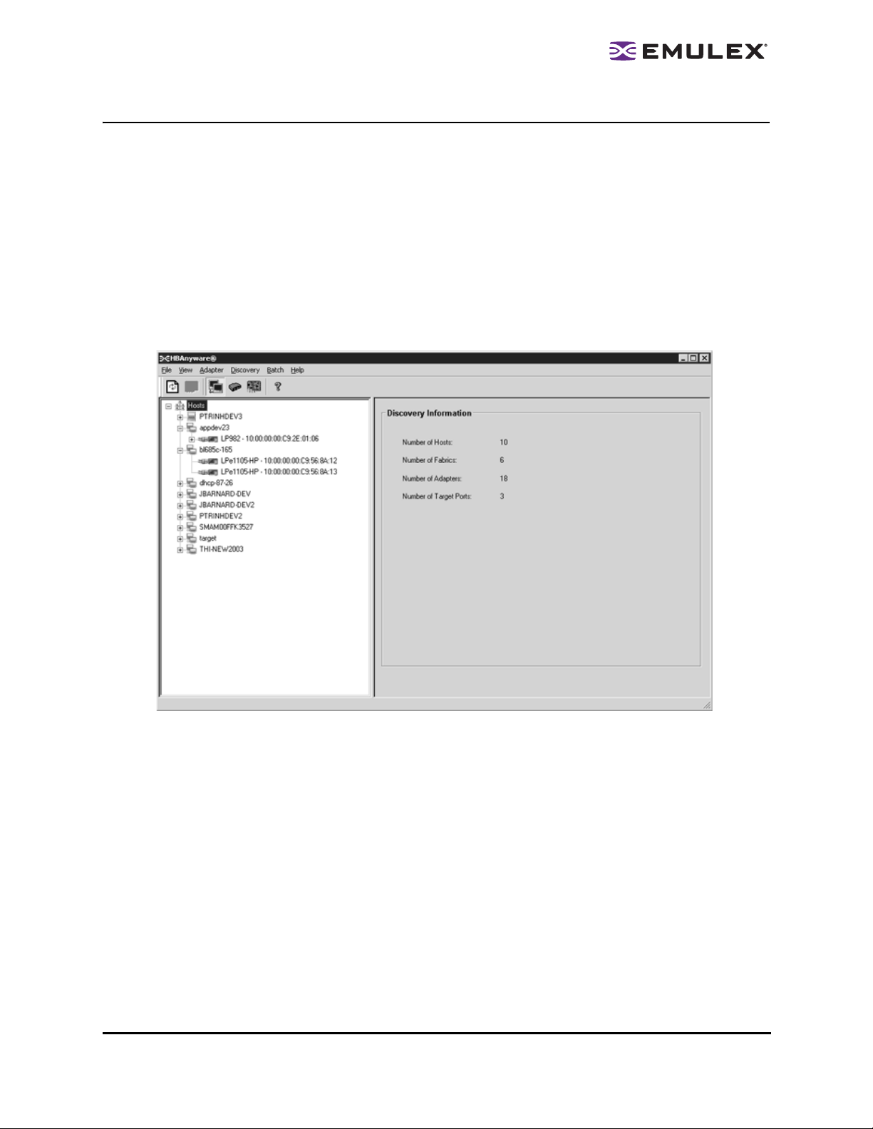
Viewing Discovery Information
Discovery Information contains a general summary of the discovered elements. The Host or Fabric icon,
depending upon which view you select, is the root of the discovery-tree, but it does not repres ent a
specific network element. Expanding it reveals all hosts, LUNs, targets and HBAs that are visible on the
SAN.
To view the discovery inform ation:
1. Click the Host or Fabric icon at the root of the discovery-tree. Discovered SAN elements appear
in the discovery-tree.
2. Select an element from the discovery-tree to learn more about it.
Figure 13: Discovery Information
Discovery Information Field Definitions
• Number of Hosts - The total number of discovered host computers. This includes servers,
workstations, personal computers, multiprocessors and clustered computer complexes.
• Number of Fabrics - The total number of discovered fabrics.
• Number of Adapters - The total number of discovered HBAs.
• Number of Target Ports - The total number of unique discovered targets on the SAN. In the
discovery-tree, the same target can appear under more than one HBA.
The HBAnyware Utility User Manual Page 25
Page 31

Viewing Host Information
There are two tabs that show host information: the Host Information tab and the Driver Parameters tab.
The Host Information tab is read-only. The Driver Parameters tab enables you to view and define HBA
driver settings for a specific host.
To view the Host Information and Driver Parameters tabs:
1. Do one of the following:
• From the menu bar, click View, then click Sort by Host Name.
• From the toolbar, click the Sort by Host Name button: .
2. Select a host in the discovery-tree.
3. Select the Host Information tab or the Driver Parameters tab.
The Host Information Tab
The Host Information tab displays information for the selected host including the number of HBAs in the
selected host, the number of fabrics to which it is connected and so on.
Figure 14: Host Information tab
Host Information Field Definitions
• Number of Adapters - The number of HBAs installed in the host.
• Number of Fabrics - The number of fabrics to which this host is attached.
• Number of Targets - The number of storage devices seen by the host.
• Remote Manager Server Version - The version of the HBAnyware utility server that is running on
the host. If different versions of the HBAnyware utility are installed on different hosts in the SAN,
those differences appear in this field.
• Host IP Address - If the host is discovered with FC, the dialog box displays "Host discovered inband". If the host has been added with TCP/IP access, the Host IP Address field displays the
host's IP address, e.g., 138.239.82.131.
The HBAnyware Utility User Manual Page 26
Page 32

The Driver Parameters Tab
The Driver Parameters tab enables you to view and edit the HBA driver settings contained in a specific
host. The host driver parameters are global values and apply to all HBAs in that host unless they are
overridden by parameters assigned to a specific HBA using the HBA Driver Parameters tab. For each
parameter, the tab shows the current value, the range of acceptable values, the default value, and
whether the parameter is dynamic (a dynamic parameter allows the change to take effect without
resetting the HBA or rebooting the system).
Note: For the Linux 2.6 kernel, most driver parameters are set globally. You can set the
lpfc_log_verbose, lpfc_nodev_tmo and lpfc_use_adisc locally.
For information on changing parameters for a single HBA, see “Setting Driver Parameters” on page 48.
For information changing parameters for the host, see “Setting Driver Parameters for All HBAs in a Host”
on page 50 .
Figure 15: Driver Parameters tab
Note: If there is more than one driver type installed, the Installed Driver Types menu show s
a list of all driver types and driver versions that are installed on the HBAs in the host.
Driver Parameters Field Definitions
• Installed Driver Type - The current driver and version installed.
• Adapter Parameter table - A list of HBA driver parameters and their current values.
Modify Adapter Parameter Area
• HBA-specific information displays in this area. This can include Value, Range, Default,
Activation Requirements and Description.
Driver Parameter Tab Buttons
• Restore - Click to save and restore parameters to this last saved value, if you have made
changes to parameters and have not saved them by clicking Apply.
• Defaults - Click to reset all parameter values to their default (out-of-box) values.
• Apply - Click to apply any driver parameter changes. If you changed a parameter that is not
dynamic, you must unload the driver and reload it.
The HBAnyware Utility User Manual Page 27
Page 33

Viewing General HBA Attributes
The General tab contains general attributes associated with the selected HBA.
To view general attributes:
1. Select Host or Fabric sort.
2. Select an HBA in the discovery-tree.
Figure 16: General tab
General Field Definitions
Adapter Summary Area
• Model - The complete model name of the HBA.
• Port WWN - The Port World Wide Name of the HBA.
• Node WWN - The Node World Wide Name of the selected HBA.
• Fabric Name or Host Name - The Fabric Name field shows if you selected, “Sort by Host Name”.
The fabric name is a 64-bit worldwide unique identifier assigned to the fabric. T he Host Name
field shows if you selected “Sort by Fabric ID”. The host name is the name of the host containing
the HBA.
• Driver Version - The version of the driver installed for the HBA.
• Firmware Versio n - The version o f Emulex firmwar e currently a ctive on the HBA.
• Driver Name - The executable file image name for the driver as it appears in the Emulex driver
download package.
• Boot Bios - Indicates if the boot code is enabled or disabled. if the boot code is enabled, shows
the boot code version. If no boot code is present on the HBA, “Not Present” is displayed in this
field.
The HBAnyware Utility User Manual Page 28
Page 34

• HBA Temperature - If supported by the selected HBA, this field displays the HBA's temperature
and one of the following temperature-related status messages:
• Normal: The HBA temperature is within normal operational range.
• Exceeded operational range - Critical: The HBA temperature is beyond norm al operational range. If the temperature continues to increase, the HBA will shut down. Y ou must
determine the cause of the temperature problem and fix it immediately. Check for system cooling issues. Common causes of system cooling issues include clogged air filters,
inoperable fans and air conditioning problems that cause high ambient air temperatures.
• Exceeded operational range - HBA stopped: The temperature has re ached critical lim it,
forcing the HBA to shut down. You must determine the cause of the temperature problem and fix it before resuming operation. Check for system cooling issues. Comm on
causes of system cooling issues include clogged air filters, inoperable fans and a ir co nditioning problems that cause high ambient air temperatures.
After the system overheating issue is resolved and the HBA has cooled down, reboot the system
or, if the system supports hot swapping, cycle the power of the HBA slot.
Adapter Status Area
• State - The current operatio nal state of the HBA: “Up”, “Down” or “Undiscovered”.
• Link Status - The current link status between the HBA and the fabric. There are several possible
states:
• The “Operational” state indicates that the HBA is connected to the network and operating
normally.
• All other states indicate that the HBA is not connected to the network. Green HBA icons with
red descriptive text indicate that the HBA is offline. These offline states are:
• “User offline” - The HBA is down or not connected to the network.
• “Bypassed” - The HBA is in FC discovery mode.
• “Diagnostic Mode” - The HBA is controlled by a diagnostic program.
• “Link Down” - There is no access to the network.
• “Port Error” - The HBA is in an unknown state; try resetting it.
• “Loopback” - An FC-1 mode in which information passed to the FC-1 transmitter is
shunted directly to the FC-1 Receiver. When a FC interface is in loopback mode, the
loopback signal overrides any external signal detected by the receiver.
• “Unknown” - The HBA is offline for an unknown reason.
• Link Sp eed - The link speed of the HBA in giga bits per second.
Viewing Detailed HBA Information
The Adapter Details tab contains detailed information associated with the selected HBA.
To view the detailed attributes:
1. Select Host or Fabric sort.
2. Select an HBA in the discovery-tree.
The HBAnyware Utility User Manual Page 29
Page 35

3. Select the Adapter Details tab.
Figure 17: Ad a pt e r Deta i ls tab
Adapter Details Field Definitions
Adapter Details Area
• Symbolic Node Name - The FC name used to register the driver with the name server.
• Hardware Version - Th e JEDEC ID board ve rsion of the selected HBA.
• Serial Number - The manufacturer assigned serial number of the selected HBA.
• Discovered Ports - Counts the number of mapped and unmapped ports found during discovery
by the Emulex HBA driver. The mapped ports are targets and the unmapped ports are non
targets such as switches or HBAs.
• Device ID - The HBA's default device ID.
Port Attributes Area
• Port FC ID - The FC ID for the port of the selected HBA.
• Port Type - The cu rrent opera tio nal mode of th e selected HBA’s port.
• OS Device Name - The platform-specific name by which the selected HBA is known to the
operating system (OS).
• Supported Class of Service - A frame delivery scheme exhibiting a set of delivery characteristics
and attributes. There are three classes of service.
• Class-1 provides a dedicated connection between a pair of ports confirmed with delivery or
notification of nondelivery.
• Class-2 provides a frame switched service with confirmed delivery or notification of
nondelivery.
• Class-3 provides a frame switched service similar to Class-2 but without notification of frame
delivery or non-delivery.
• Supported FC4 Types - A 256-bit (8-word) map of the FC-4 protocol types supported by the port
containing the selected HBA.
The HBAnyware Utility User Manual Page 30
Page 36

Loop Map Area
• The loop map shows the different ports present in the loop, and is present only if the port (HBA)
is operating in loop mode. The simplest exam ple would be to con nect a JBOD directly to a n
HBA. When this is done, the port type will be a private loop, and the loop map will have an entry
for the HBA, and one entry for each of the disks in the JBOD.
Viewing Fabric Information
Discovery Information contains information about the selected fabric.
To view the fabric information:
1. Do one of the following:
• From the menu bar, click View, then click Sort by Fabric ID.
• From the toolbar, click the Sort by Fabric ID button: .
2. Click on a fabric address in the discovery-tree. The Discovery Information tab shows information
about the selected fabric.
Figure 18: Discovery Information
Discovery Information Field Definitions
• Number of Hosts - The number of hosts discovered or seen by this host on the selected fabric.
• Number of Fabrics - The number fabrics identified during discovery.
• Number of Adapters - The number of HBAs discovered by this host on the selected fabric.
• Number of Target Ports - The number of storage devices seen by this host on the selected
fabric.
The HBAnyware Utility User Manual Page 31
Page 37

Viewing Targ et Information
Target Information contains informa tion specific to the selected storage de vice.
To view target information:
1. Do one of the following:
• From the menu bar, click View, then click Sort by Host Name.
• From the toolbar, click the Sort by Host Name button: .
2. Click a target in the discovery-tree. The Target Information tab appears.
Figure 19: Target Information tab
Target Information Field Definitions
• Mapping Information Area
• FC ID - The FC ID for the target; assigned automatically in the firmware.
• SCSI Bus Number - The SCSI Bus number to which the target is mapped.
• SCSI Target Number - The target's identifier on th e SCSI Bus.
• Node WWN - A unique 64-bit number, in hexadecimal, for the target (N_PORT or
NL_PORT).
• Port WWN - A unique 64-bit number, in hexadecimal, for the fabric (F_POR T or
Fabric Loop Port [
FL_PORT]).
Switched
• OS Device Name - The OS device name.
The HBAnyware Utility User Manual Page 32
Page 38

Viewing LUN Information
LUN Information contains details about the selected LUN.
To view the LUN information:
1. Do one of the following:
• From the menu bar, click View, then click Sort by Host Name.
• From the toolbar, click the Sort by Host Name button: .
2. Select a LUN in the discovery-tree.
Figure 20: LUN Information
LUN Information Field Definitions
• Vendor Product Information Are a
• Vendor Name - The name of the vendor of the LUN.
• Product Name - The vendor-specific ID for the LUN.
• Revision - The vendor-specific revision number for the LUN.
• Mapping Information Area
• FCP LUN - The FC identifier used by the HBA to map to the SCSI OS LUN.
• SCSI OS LUN - The SCSI identifier used by the OS to map to the specific LUN.
• OS Device Name - The name assigned by the OS to the LUN.
• LUN Capacity Area
Note: LUN capacity information is only provided when the LUN is a mass-storage (disk)
device. Other devices like tapes and scanners, etc. do not display capacity.
• Capacity - The capacity of the LUN, in megabytes.
• Block Size - The length of a logical unit block in bytes.
• LUN Masking Area
• Current Masking State - Possible states are masked or unmasked.
The HBAnyware Utility User Manual Page 33
Page 39

Masking and Unmasking LUNs (Windows, Solaris LPFC and Solaris emlxs (SFS))
LUN masking refers to whether or not a LUN is visible to the operating system. A LUN that has been
masked is not available and is not visible to the OS. You can use HBAnyware to mask or unmask LUNs
at the host level.
Note: In Solaris systems, the Emulex LPFC drivers support both a target level and HBA
level LUN unmasking over ri de feature. If either of these driver-specific overrides are
enabled, the HBAnyware utility will not permit you to configure LUN masking. In this
case you must change the LUN masking level to the correct level from the LUN
masking tab before you can mask or unmask LUNs (see Figure 21).
Figure 21: LUN Masking tab with LUN Masking Disabled
LUN Masking Conventions and Guidelines
LUN icons in the discovery-tree reflect the live mask state currently in use by the driver. Green LUN
icons indicate unmasked LUNs. Grey LUN icons indicate masked LUNs. Red text indicates that a LUN
mask has been changed, but not applied (saved).
LUN Masking Column Definitions
• LUN – The FC LUN number.
• On Reboot – The 'On Reboot' column shows the mask configuration currently saved to the
configuration file on disk (Solaris LPFC and Solaris emlxs (SFS)) or to the Registry (Windows).
Normally, for a specific LUN, the states reported in the 'On Reboot' and 'Current' column will be
identical. However, there may be times where these do not match. For example, the hbacmd
tool may be used to change only the 'Current' mask state for a LUN and not touch the 'On
Reboot' mask state contained in the configuration file.
• Current – The 'Current' column displays the live mask state currently in use by the driver. When
you first see the LUN Masking tab, the mask states displayed in the 'Current' column are
identical to the mask states for the corresponding LUNs in the discovery-tree.
The HBAnyware Utility User Manual Page 34
Page 40

To change the mask status of a LUN:
1. From the discovery-tree, click on a SCSI target. A set of LUNs appears below the selected SCSI
target. The LUN Masking tab is displayed. This tab contains a list of the same set of LUNs
appear below the SCSI target.
Figure 22: LUN Masking tab
2. In the LUN list of the LUN Masking tab, select one or more LUNs. The LUN Masking tab buttons
become active as is appropriate. For example, if the currently selected LUN is masked, the
Unmask Selected LUNs and Unmask All LUNs buttons are active.
3. Change the mask status. Mask status changes appear in red text. The Restore and Apply
buttons are active.
Note: To return all mask settings to their status before you started this procedure, click
Restore before you click Apply. Once you click Apply, changes cannot be cancelled
by clicking Restore. To unmask all LUNs, click Unmask All LUNs. This button is
always active. Be sure to also click Apply to commit the changes.
4. Click Apply to commit the changes. An informational message is displayed that confirms the
mask status has changed and the red text changes to black.
Viewing Port Statistics
The Statistics tab provides cumulative totals for various error events and statistics on the port. Some
statistics are cleared when the HBA is reset.
To view port statistics:
1. Select Host or Fabric sort.
2. Select an HBA in the discovery-tree.
The HBAnyware Utility User Manual Page 35
Page 41

3. Click the Statistics tab.
Figure 23: Statistics tab
Port Statistics Field Definitions
• Tx Frames - FC frames transmitted by this HBA port.
• Tx Words - FC words transmitted by this HBA port.
• Tx KB Count - FC kilobytes transmitted by this HBA port.
• Tx Sequences - FC sequences transmitted by this HBA port.
• LIP count - The number of loop initialization primitive (LIP) events that have occurred for the
port. This field is not supported if the topology is not arbitrated loop. Loop initialization consists
of the following:
• Temporarily suspend loop operations.
• Determine whether loop capable ports are connected to the loop.
• Assign AL_PA IDs.
• Provide notification of configuration changes and loop failures.
• Place loop ports in the monitoring state.
• Error Frames - The number of frames received with cyclic redundancy check (CRC) errors.
• Link Failures - The number of times the link failed. A link failure is a possible cause of a timeout.
• Loss of Signal - The number of times the signal was lost.
• Invalid Tx Words - The total number of invalid words transmitted by this HBA port.
• Ex Count Orig - The number of FC exchanges originating on this port.
• Active XRIs - The number of active exchange resource indicators.
• Received P_BSY - The number of FC port-busy link response frames received.
• Link Transitions - The number of times the SLI port sent a link attention condition.
• Elastic Buf Overruns - The number of times the link interface has had its elastic buffer overrun.
• Rx Frames - The number of FC frames received by this HBA port.
The HBAnyware Utility User Manual Page 36
Page 42

• Rx Words - The number of FC words received by this HBA port.
• Rx KB Count - The received kilobyte count by this HBA port.
• Rx Sequences - The number of FC sequences received by this HBA port.
• NOS count - This statistic is currently not supported for the SCSIport Miniport and Storport
Miniport drivers, nor is it supported for arbitrated loop.
• Dumped Frames - This statistic is not currently supported for the SCSIport Miniport driver, the
Storport Miniport driver or the driver for Solaris.
• Loss of Sync - The number of times loss of synchronization has occurred.
• Prim Seq Prot Errs - The primitive sequence protocol error count. This counter is incremented
whenever there is any type of protocol error.
• Invalid CRCs - The number of frames received that contain CRC failures.
• Ex Count Resp - The number of FC exchange responses made by this port.
• Active RPIs - The number of remote port indicators.
• Receive F_BSY - The number of FC port-busy link response frames received.
• Primitive Seq Time outs - The number of times a p rimitive seque nce event timed o ut.
• Arbitration Timeouts - The number of times the arbitration loop has timed out. Large counts
could indicate a malfunction somewhere in the loop or heavy usag e of the lo op.
Viewing Firmware Information
Use the Firmware tab to view current firmware versions, enable system BIOS and update firmware on
remote and local HBAs.
To view the firmware information:
1. Select Host or Fabric sort.
2. Select an HBA in the discovery-tree.
3. Select the Firmware tab.
Figure 24: Firmware tab
The HBAnyware Utility User Manual Page 37
Page 43

Firmware Field Definitions
• Firmware Area
• Current Firmware Version - The Emulex firmware version number for this model of HBA.
• Operational Firmware Name - If visible, the name of the firmware that is opera tional.
• Initial Firmware - The firmware version stub responsible for installing SLI code into its slot.
• SLI-1 Firmware Name - The name of the SLI-1 firmware overlay.
• SLI-2 Firmware Name - The name of the SLI-2 firmware overlay.
• SLI-3 Firmware Name - The name of the SLI-3 firmware overlay.
• Kernel Version - The version of the firmware responsible for starting the driver.
• Boot BIOS Area
• Boot Bios - Indicates if the boot code is enabled or disabled. If enabled, shows the boot code
version. If no boot code is present on the HBA, “Not Present” is displayed in this field.
Firmware Tab Bu ttons
• Update Firmware - Click to display the HBAnyware Firmware Download dialog box. Browse to
the file you wish to download and download the file. See the “Update Firmware Using
HBAnyware” topic on page 43 for more information.
• Enable/Disable - Click to enable or disable the x86 BootBIOS code.
Viewing Target Map ping (Windows, Solaris LPFC and Solaris emlxs (SFS))
The Target Map ping tab enables you to view current target mapping and to set up persistent binding.
To view target mapping:
1. Select Host or Fabric sort.
2. Select the HBA in the discovery-tree whose target mapping information you wish to view.
3. Select the Target Mapping tab.
Figure 25: Target Mapping tab
The HBAnyware Utility User Manual Page 38
Page 44

Target Mapping Field Definitions
Current Settings Area
• Active Bind Type - WWPN, WWNN, or a destination identifier (D_ID).
• Automapping - The current state of SCSI device automapping: enabled (default) or disabled.
Current Mappings Area
• This table lists current mapping information for the selected HBA.
Persistent Binding Configuration Area
• This table lists persistent binding information for the selected HBA.
Display Mode Radio Buttons
• Show WWPN, Show WWNN or Show D_ID.
Target Mapping Buttons
• Refresh - Click to refresh the Target Mapping tab.
• Change Settings - Click to change the active bind type (the mode used to persistently bind target
mappings), LUN automapping or LUN unmasking settings. The Mapped Target Setting window
is displayed. Select the active bind type (WWPN, WWNN, D_ID or AL_PA), set LUN
automapping to enabled or disabled, and/or set LUN unmasking to enabled or disabled.
• Add Binding - Click to add a persistent binding.
• Bind New - Click to add a target that does not appear in the Persistent Binding table.
• Remove - Click to remove the selected binding.
• Remove All - Click to remove all persistent bindings that are displayed.
Viewing Target Mapping (Linux)
Use this tab to view target mapping. The Target Mapping tab is read-only.
Note: Persistent binding is not supported by the Linux 2.6 ke rnel or by the Emulex version 8.0 driver for Linux.
To view target mapping:
1. Select Host or Fabric sort.
2. Select the HBA in the discovery-tree whose target mapping information you wish to view.
The HBAnyware Utility User Manual Page 39
Page 45

3. Select the Target Mapping tab.
Figure 26: Target Mapping tab
Target Mapping Field Definitions
Current Settings Area
• Active Bind Type -N/A
• Automapping - N/A
Current Mappings Area
• This table lists current mapping information for the selected HBA.
Persistent Binding Configuration Area
•N/A
Display Mode Radio Buttons
•N/A
Target Mapping Buttons
•N/A
Viewing and Setting Up Authentication (Windows, Linux 8.2, Solaris LPFC and Solaris emlxs (SFS))
Use the Authenticate tab to view and configure FC-SP DH-CHAP. Once DH-CHAP has been activate d
and configured, manually initiate authentication per HBA by clicking on the Initiate Authentication button
or by inducing a fabric login (FLOGI) time per the FC-SP standard to the switch. A FLOGI can also be
caused by bringing the link between the switch and HBA down and then up.
Note: For Linux, authentication is only supported on driver version 8.2.
Authentication must first be enabled at the driver level. Authentication is disable d by default. Prior to
enabling Authentication at the driver level, the text fields under the Authentication tab will be greyed out.
The Authentication tab is used to configure the mode of authentication for each HBA port.
The HBAnyware Utility User Manual Page 40
Page 46

To enable DH-CHAP using the Drivers Parameters tab, enable the enable-auth parameter (in Windows),
the auth-mode parameter (in Solaris LPFC) or lpfc-enable-auth (in Linux 8.2).
Figure 27: Authentication tab
Authenticate Tab Field Definitions
• Source - The HBA identifier WWPN of the HBA port)
• Destination - The fabric switch name.
Configuration Data Area
• Mode - The mode of operation. There are three modes: Enabled, Passive and Disabled.
• Enabled - The HBA will initiate authentication after issuing an FLOGI to the switch. If the
connecting device does not support DH-CHAP authentication, the software continues with
the rest of the initialization sequence.
• Passive - The HBA does not initiate authentication, but participates in the authentication
process if the connecting device initiates an authentication request.
• Disabled - The HBA does not initiate authentication or participate in the authentication
process when initiated by a connecting device. This is the default mode.
• Timeout - During the DH-CHAP protocol exchange, if the switch does not receive the expected
DH-CHAP message within a specified time interval, authentication failure is assumed (no
authentication is performed). The time value ranges from 20 to 999 seconds.
• Bi-Directional - If selected, the driver (HBA) supports authentication initiated by either (both) the
switch or the HBA. If this check box is clear, the driver supports HBA initiated authentication
only.
• Re-authenticate - If selected, the driver can periodically initiate authentication.
• Re-authorization interval - The value in minutes that driver (HBA) will use to periodically initiate
authentication. Valid interval ranges are between 10 to 3600 minutes. The default is 300.
• DH Priority - The priority of the 5 supported DH Groups (Null group, and groups 1,2,3, and 4)
that the driver (HBA) presents during the DH-CHAP authentication negotiation with the switch.
The HBAnyware Utility User Manual Page 41
Page 47

• Hash Priority - The priority of the two supported hash algorithms (MD5 and SHA1) that the driver
(HBA) presents during the DH-CHAP authentication negotiation with the switch (default is MD5
first, then SHA1.)
Viewing or Changing Authentication Configuration
To view or change authenticatio n configu ration:
1. In the discovery tree, click the HBA.
2. Select the Authenticate tab. The Authenticate tab is displayed. (If the fields on this tab are
greyed out (disabled) authentication has not been enabled at the driver level.)
3. If you wish, change configuration values and click Apply. You are prompted for the current
password (local password) to validate the configuration change request. The verification request
only appears if a local password has been defined for this HBA.
To return setting s to the status befor e you started this pro cedu re, click Restore before you click
Apply. Once you click Apply, changes can not be cancelled.
To return all settings (the configuration) to the default configuration, click Defaults. Be careful as
this also resets the password(s) to NULL for this configuration.
To initiate an immediate authentication, click Initiate Authentication. This request is sent to the
driver, even if you have not made any changes to the setup.
Note: To successfully authenticate with the switch using DH-CHAP, you only need to set the
configuration mode to enabled and set the local password. The local password must
be set to the identical value as the switch for the DH-CHAP authentication to
succeed.
Changing Your Password
1. Click Password on the Authenticate tab.
2. Select ASCII text or binary (Hex input) format.
3. Select local or remote password.
• Local password is used by the driver (HBA) wh en the HBA in itiates auth enticati on to the
switch (typical use).
• Remote password is used by driver (HBA) when the switch authenticates with the HBA.
The latter is only possible when bi-directional has been checked on the configuration.
4. Provide the current value for the password to validate the 'set new password' request
(unnecessary if this is the first time the password is set for a given HBA).
Caution: Do not forget the password once one has been assigned. Once a password is
assigned to an HBA, subsequent DH-CHAP configuration settings for that HBA
including 'default configuration' or new passwords require you to enter the existing
password to validate your request (i.e. no further changes can be made without
the password).
Note: Additional help is available by clicking Help on the Set Password dialog box.
The HBAnyware Utility User Manual Page 42
Page 48

Updating Firmware
Prerequisites
• The Emulex driver is installed:
• The HBAnyware utility is installed.
• The firmware zip file is downloaded from the Emulex Web site, unzipped and extracted to a
folder on a local drive.
• If the HBA is already connected to a boot device, the system is in a state in which this type of
maintenance can be performed:
• I/O activity on the Bus has been stopped.
• Cluster software, or any other software that relies on the HBA to be available, is stopped
or paused.
Yo u can update firm ware on local and rem ote HBAs. The firm ware file must be do wnlo aded from the
Emulex Web site and extracted to a local drive before you can perform this procedure.
Note: For OEM branded HBAs, see the OEM’s Web site or contact the OEM’s customer
service department or technical support department for the firmware files.
To update firmware:
1. In the discovery-tree, click the HBA on which you want to update th e firmware. The General tab
appears.
2. In the property tabs, select the Firmware tab.
3. Do one of the following:
• In versions 3.0 or later, click Up date Fir mware on th e Fir mware t a b. The messa ge i n Figu re
28 may appear. If this message appears, click Yes.
Figure 28: Reset message
• In versions earlier than 3.0, click Browse on the Firmware tab. The Select Firmware File
dialog box appears. Proceed to step 5.
The HBAnyware Utility User Manual Page 43
Page 49

4. In HBAnyware versions 3.0 or later, after you click Update Firmware, the Firmware Download
dialog box appears (Figure 29).
Figure 29: Firmware Download d ialog b ox f or Win dow s
5. For all versions of HBAnyware, use the Firmware Download dialog box to navigate to the
unzipped, extracted image file you want to download.
6. Select the file and click Start Download (version 3.0 or later) or OK (versions earlier than 3.0).
A status bar shows the progress of the download and indicates when the download is complete.
In versions earlier than 3.0, the HBA in the discovery tree is displayed in red text, indicating that
it is offline. It is displayed in black text when the update is complete.
7. Click Close.
8. Repeat steps 2 through 8 to update boot code on additional HBAs.
Updating Firmware (Batch Mode)
Batch mode allows you to update boot code on multiple HBAs in a single step . Batch mo de is restricted
to a single boot code image.
Note: No other HBA functions can be performed while boot code update in batch mode is in
progress.
To update boot code using b atch mode:
1. Start the HBAnyware utility (see page 3).
2. From the menu bar, select Batch and click Download Firmware.
The HBAnyware Utility User Manual Page 44
Page 50

3. Navigate to the extracted boot code image file you want to download. Boot code imag es have a
.prg extension. Select the boot code file and click Open. A tree-view shows all HBAs, and their
corresponding hosts, that are compatible with the selected boot code file (Figure 30).
Figure 30: Selecting HBAs to Update screen fo r Window s
4. Click the box next to an HBA to select or remove the HBA from the batch process. Click the box
next to a host to select or remove all eligible HBAs for the host from the batch process.
5. Click Start Download.
When downloading begins, the tree-view displays the progress. As the image for a selected
HBA is being downloaded, it appears orange in the tree-view. When the download is complete,
the entry changes to green. Figure 31 is an example of successfully downloaded images. If th e
The HBAnyware Utility User Manual Page 45
Page 51

download fails, the entry changes to red and failure information appears at the bottom of the
screen.
Figure 31: Download Complete screen for Win do ws
6. When downloading is finished, click Print Log to print a hard copy of the activity log.
Note: Printing is not supported in Linux.
7. Click Close to exit the batch procedure.
8. Click Close.
9. Repeat steps 2 through 8 to update boot code on additional HBAs.
The HBAnyware Utility User Manual Page 46
Page 52

Enabling or Disabling an HBA’s BIOS
Enabling the BIOS is a two-step process:
1. Enable the HBA BIOS (x86 BootBIOS, FCode or EFIBoot) to read the Emulex boot code on the
HBA.
2. Enable the HBA to boot from SAN (using the BIOS utility).
The Emulex boot code must be downloaded from the Emulex Web site and extracted to a local drive
before you can perform this procedure.
To enable or disable the HBA BIOS:
1. In the discovery-tree, select the HBA.
2. Select the Firmware tab.
Figure 32: Firmware Tab with BIOS Disabled
3. To enable the BIOS, click Enable. The button title changes from Enable to Disable.
Or
To disable the BIOS, click Disable. The button title changes from Disable to Enable.
Note: If you are updating x86 BootBIOS, you must also enable the HBA to boot from SAN
using the BIOS utility; see the documentation that accompanies the boot code for
more information.
Note: If no boot code is present on the HBA, “Not Present” is displayed in the Boot BIOS
field and the button is not be visible.
Note: If the BIOS state on the board changes, the change reflects immediately on the
General tab, as well as the Firmware tab.
The HBAnyware Utility User Manual Page 47
Page 53

Configuring the Driver
In Windows, Solaris LPFC, Solaris emlxs (SFS) and Linux: Set driver parameters using the HBAnyware
utility. In Solaris LPFC, Solaris emlxs (SFS) and Linux:, you can also specify parameters when loading
the driver manually. See the appropriate driver manual for instructions.
Setting Driver Parameters
The Driver Parameters tab and host Driver Parameter tab enable you to modify driver parameters for a
specific HBA or all HBAs in a host.
For example, if you select a host in the discovery-tree, you can globally change the parameters for all
HBAs in that host. If you select an HBA in the discovery-tree, you can change the lpfc_use_adisc,
lpfc_log_verbose and the lpfc_nodev_tmo parameters for only that HBA.
For each parameter, the Driver Parameters tab and host Driver Parameters tab shows the current value,
the range of acceptable values, the default value, and the activation requirement. You can also restore
parameters to their default settings.
Yo u can apply driver parameters for one HBA to othe r HBAs in the syste m using the Driver Para meters
tab, thereby simplifying multiple HBA configuration. See “Creating and Assigning a Batch Mode Driver
Parameters File” on page 52 for more information.
Note: The Linux 2.6 kernel only supports setting the log_verbose, nodev_tmo and
use_adisk driver parameters for individual HBAs. You must apply other driver
parameters to all HBAs contained in the host.
To change the driver parameters for a single HBA:
1. Do one of the following:
• From the menu bar, click View, then click Sort by Host Name.
• From the toolbar, click the Sort by Host Name button: .
2. In the discovery-tree, select the HBA.
The HBAnyware Utility User Manual Page 48
Page 54

3. Select the Driver Parameters tab. The parameter values for the selected HBA are displayed.
Figure 33: Driver Parameters tab - HBA Selected
4. In the Driver Parameters tab, click the parameter that you want to change. A description of the
parameter appears on the right side of the tab.
5. Enter a new value in the Value field in the same hexadecimal or decimal format as the current
value. If the current value is in hexadecimal format, it is prefaced by "0x" (for example, 0x2d).
You may enter a new hexadecimal value without the "0x". For example, if you enter ff10, this
value is interpreted and displayed as "0xff10".
6. If you want the change to be temporary (causing the parameter to revert to its last permanent
setting when the system is rebooted), check the Make change temporary box. T his option is
available only for dynamic parameters.
7. If you are making changes to multiple parameters, and you want all the changes to be
temporary, check the Make all changes temporary box. This setting overrides the setting of the
Make change temporary box. Only dynamic parameters can be made temporary.
8. Click Apply.
Restoring All Parameters to Their Earlier Values
If you changed parameters, but did not click Apply and you want to restore the parameters to their last
saved values, click Restore.
Resetting All Default Values
To reset all parameter values to their default (factory) valu es, click Defaults.
The HBAnyware Utility User Manual Page 49
Page 55

Setting an HBA Parameter Value to the Host Parameter Value
To set an HBA parameter value(s) to the correspo nding host parameter value(s):
1. In the discovery-tree, select the HBA.
2. Select the Driver Parameters tab.
3. Click Globals. All parameter values are now the same as the global, or host, values.
4. To apply the global values, click Apply.
Saving HBA Driver Parameters to a File
To save HBA driver parameters, click Save (or Save Settings). Each definition is saved in a commadelimited file with the following format:
<parameter-name>=<parameter-value>
The file is saved in the Emulex Repository directory. HBAnyware can then use the Batch Driver
Parameter Update function to apply these saved settings to any or all compatible HBAs on the SAN.
Note: Persistent binding settings cannot be saved with the Save (or Save Settings) feature.
Setting Driver Parameters for All HBAs in a Host
To change the driver parameters for all HBAs installed in a host:
1. Do one of the following:
• From the menu bar, click View, then click Sort by Host Name.
• From the toolbar, click the Sort by Host Name button: .
2. In the discovery-tree, click the host whose HBA driver parameters you wish to change.
3. Select the Driver Parameters tab. If there are HBAs with different driver types installed, the
Installed Driver Types menu shows a list of all driver types and driver versions that are installed.
Select the driver whose parameters you wish to change. This menu does not appear if all the
HBAs are using the same driver.
4. In the Driver Parameters tab, click the parameter that you want to change. A description of the
parameter appears on the right side of the dialog box.
The HBAnyware Utility User Manual Page 50
Page 56

Figure 34: Driver Parameters tab - Host Selected
5. Enter a new value in the Value field in decimal or hexadecimal format, depending on how the
current value is presented. If the value is in hexadecimal form at, it is prefaced b y "0 x" (for
example” 0x2d”).
6. To make a change tempora ry (the parameter to revert to its last permanent setting whe n the
system is rebooted), check the Make changes temporary box. This option is available only for
dynamic parameters.
7. To make changes to mu ltiple parameters, check the Ma ke all chan ges tempora ry box. Only
dynamic parameters can be made temporary.
8. Click Apply.
Changing Non-dynamic Parameter Values (Linux)
To change non-d ynamic parameter values:
1. Navigate to the /usr/sbin/hbanyware directory and run the scripts to stop the HBAnyware utility
processes. Type:
./stop_hbanyware
2. Stop all I/O to LPFC attached devices.
3. Unload the lpfcdfc driver. Type:
rmmod lpfcdfc
4. Unload the LPFC driver. Type:
rmmod lpfc
5. Reload the driver.Type:
modprobe lpfc
modprobe lpfcdfc
The HBAnyware services will start automatically when you launch the application.
For these changes to persist after a reboot you must create a new ramdisk image.
The HBAnyware Utility User Manual Page 51
Page 57

Creating and Assigning a Batch Mode Driver Parameters File
Yo u can apply driver parameters for one HBA to othe r HBAs in the syste m using the Driver Para meters
tab. When you define parameters for an HBA, you create a .dpv file. The .dpv file contains parameters
for that HBA. After you create the .dpv file, the HBAnyware utility enables you to assign the .dpv file
parameters to multiple HBAs in the system.
To create and assign the .dpv file:
1. Select the HBA whose parameters you want to apply to other HBAs from the discovery-tree.
2. Select the Driver Parameters tab.
3. Set the driver parameters.
4. After you define the parameters for the selected HBA, click Apply.
5. Click Save (or Save Settings). The Select Driver Parameter File browse window appears.
Figure 35: Select Driver Parameter File browse window
6. Use the Select Driver Parameter File dialog box to bro wse to where you want to save the file or
to rename the file.
7. Click Save. The Save Driver Parameters dialog box appears.
Figure 36: Save Driver Parameters dialog box
The HBAnyware Utility User Manual Page 52
Page 58

8. The two radio buttons allow you to choose the type of parameters to save. You can save all
parameters or only those parameters whose current values differ from their corresponding
default values.
A list of the saved parameters and their current values show in the Saved Parameters box.
9. Click Save.
10. Assign batch mode parameters to HBAs: From the Batch menu select Update Driver
Parameters. (You do not need to select any discovery-tree elements at this time.) The Select
Driver Parameter File dialog box appears.
1 1. Select the file whose parameters you wish to apply and click Open. The Batch Driver Parameter
Update dialog box shows all the batch file compatible HBAs with a check mark beside them.
Figure 37: Batch Driver Parameters Update dialog box for Windows
Note: Solaris LPFC, Solaris emlxs (SFS) and Linux: A Browse button is included on the
Batch Driver Parameters Update dialog box. The Browse button allows you to
navigate to a different file.
12. Click Start. The HBAnyware Batch Driver Update dialo g box shows the current status of the
update. When the update completes, a final summary shows the number o f HBAs tha t were
successfully processed, and the number of HBAs for which one or more parameter upd ates
failed.
13. If you wish, click Print Log to print a report of the update.
Note: Printing is not supported in Linux.
The HBAnyware Utility User Manual Page 53
Page 59

Storport Miniport Driver Parameters
The parameter values listed in Table 1 are applicable to driver version 2.00 or later. If you are using a
version previous to 2.00, see the Storport Miniport Driver User Manual for parameter information.
Activation Requirements
A parameter has one of the following activation requirements:
• Dynamic - The change takes effect while the system is running.
• Reset - Requires an HBA reset from the utility before the change takes effect.
• Reboot - Requires reboot of the entire machine before the change effect. In this case, you are
prompted to do reboot when you exit the utility.
The Driver Parameter table provides information such as the allowable range of values and factory
defaults. Parameters can be entered in decimal or hexadecimal format.
Note: If you are creating custom unattended installation scripts, any driver
parameter can be modified and included in the script.
Most parameters default to a setting that optimizes HBA performance.
Table 1: Storport Miniport Driver Parameters
Parameter Definitions
AutoMap=n AutoMap controls the way targets are assigned SCSI IDs. Discovere d
targets are assigned persistent SCSI IDs according to the selected
binding method. Persistent bindings do not take effect with the driver
in stand-alone mode.
If set to 0 = automap is disabled. Uses the HBAnyware utility to
persistently set the SCSI address of a discovered FCP capable FC
node (target).
If set to 1 = automap by WWNN.
If set to 2 = automap by WWPN.
If set to 3 = automap by DID).
Value: 0 - 3
Default = 2
Class=n Class selects the class of service on FCP commands.
If set to 2, class = 2.
If set to 3, class = 3.
Value: 2 - 3
Default = 3
CoalesceMsCnt=n CoalesceMsCn specifies wait time in milliseconds to generate an
interrupt response if CoalesceRspCnt has not been satisfied. Zero
specifies an immediate interrupt response notification. A non-zero
value enables response coalescing at the specified interval in
milliseconds.
Activation
Requirement
Reboot
Dynamic
Reset
Value: 0 - 63 (decimal) or 0x0 - 0x3F (hex)
Default = 0 (0x0)
The HBAnyware Utility User Manual Page 54
Page 60

Table 1: Storport Miniport Driver Parameters (Continued)
Parameter Definitions
CoalesceRspCnt=n CoalesceRspCn specifies the number of response entries that trigger
an Interrupt response.
Value: 0 - 255 (decimal) or 0x1 - 0xFF (hex)
Default = 8 (0x8)
DiscoveryDelay=n DiscoveryDelay controls whether the driver waits for ‘n’ seconds to
start port discovery after link up.
If set to 0 = immediate discovery after link up.
If set to 1 or 2 = the number of seconds to wait after link-up before
starting port discovery.
Value: 0 - 2 seconds (decimal)
Default = 0.
EnableAck0=n Set to 1 to force sequence rather than frame level acknowledgement
for class 2 traffic over an exchange. This applies to FCP data
exchanges on IREAD and IWRITE commands.
Value: 0 - 1 (decimal)
Default = 0
EnableAUTH EnableAUTH enables fabric authentication. This feature requires the
authentication to be supported by the fabric. Authentication is enabled
when this value is set to 1.
Activation
Requirement
Reset
Dynamic
Reset
Reboot
Value: 0 - 1
Default = 0
EnableFDMI=n If set to 1, enables management server login on fabric discovery. This
allows Fabric-Device Management Interface (FDMI) to operate on
switches that have FDMI-capable firmware.
If set to 2, FDMI operates and uses the host name feature of FDMI.
Value: 0 -2 (decimal)
Default = 0
EnableNPIV=n If set to 1, enables N_Port_ID virtualization (NPIV). Requires NPIV
supported firmware and HBA.
Value: 0 -1
Default = 0 (disabled)
Note: To run the driver using NPIV or SLI-3 optimization, the firmware
must be version 2.72a0 or later. If an earlier version is used, the driver
will run in SLI-2 mode and will not support NPIV.
FrameSizeMSB=n FrameSizeMSB controls the upper byte of receive FrameSize if
issued in PLOGI. This allows the FrameSize to be constrained on
256-byte increments from 256 (1) to 2048 (8).
Value: 0 - 8
Default = 0
Reset
Reset
Reset
The HBAnyware Utility User Manual Page 55
Page 61

Table 1: Storport Miniport Driver Parameters (Continued)
Parameter Definitions
HardALPA=0xn HardALPA allows the HBA to use a hard assigned loop address.
Value: 0x00 - 0xEF (hex)
Default = 0x00 (use soft addressing, or flash stored hard address
value)
Note: Only valid AL_PAs may be used.
InitTimeout=n Determines the number of time-out seco nds during drive r initializa tion
for the link to come up. If the link fails to come up by InitTmeout, driver
initialization exits but is still successful. If the link comes up before
InitTimeout, the driver sets double the amount for discovery to
complete.
Value: 5 -30 seconds or 0x5 - 0x1E (hex)
Default = 15 seconds (0xF)
LinkSpeed=n LinkSpeed has significance only if the HBA supports speeds other
than one Gbit.
If set to 0 = auto link speed detection.
If set to 1 = 1 Gbit.
If set to 2 = 2 Gbit.
If set to 4 = 4 Gbit.
If set to 8 = 8 Gbit.
Activation
Requirement
Reset
Reboot
Reset
Value: 0, 1, 2, 4 and 8
Default = 0
Note: Setting this option incorrectly may cause the HBA to fail to
initialize.
LinkTimeOut=n LinkTimeOut applies to private loop only. A timer is started on all
mapped targets using the link timeout value. If the timer expires
before discovery is re-resolved, commands issued to timed out
devices will end up returning a SELECTIION_TIMEOUT. The Storport
driver will also be notified of a Bus change event which will lead to the
removal of all LUNs on the timed out devices.
Value: 1 - 500 seconds or 0x0 - 0xFE (hex)
Default = 30 (0x1E)
Dynamic
The HBAnyware Utility User Manual Page 56
Page 62

Table 1: Storport Miniport Driver Parameters (Continued)
Parameter Definitions
LogErrors=n LogErrors determine the minimum severity level required to enable
entry of a logged error into the system event log. Errors are classified
as severe, malfunction or command level. A severe error requires
user intervention to correct a firmware or HBA problem. An invalid link
speed selection is an example of a severe error. A malfunction error
indicates that the system has problems, but user intervention is not
required. An invalid fabric command type is an example of a
malfunction error. A command level error: an object allocation failure
is an example of a command error.
If set to 0, all errors regardless of severity are logged.
If set to 1, command level errors are logged.
If set to 2, malfunction errors are logged.
If set to 3, severe errors are logged.
Value: 0 - 3
Default = 3
NetworkOption=n NetworkOption controls whether IP over FC is disabled or enabled.
A value of 1 will enable IP over FC and will allow first time installation
or startup of the FC LAN driver.
Value: 0 - 1
Default = 0
Activation
Requirement
Dynamic
NodeTimeout=n The node timer starts when a node (i.e. discovered target or initiator)
becomes unavailable. If the node fails to become available before the
NodeTimeout interval expires, the OS is notified so that any
associated devices (if the node is a target) can be removed. If the
node becomes available before NodeTimeout expires the timer is
canceled and no notification is made.
Value: 1 - 255 seconds or 0x0 - 0xFF (hex)
Default = 30 (0x1E)
QueueDepth=n QueueDepth requests per LUN/target (see QueueTarget parameter).
If you expect the number of outstanding I/Os per device to exceed 32,
then you must increase to a value greater than the number of
expected I/Os per device (up to a value of 254). If the QueueDepth
value is set too low, a performance degradation can occur due to
driver throttling of its device queue.
Value: 1 - 254 or 0x1 - 0xFE (hex)
Default = 32 (0x20)
QueueTarget=n QueueTarget controls I/O depth limiting on a per target or per LUN
basis.
If set to 0 = depth limitation is applied to individual LUNs.
If set to 1 = depth limitation is applied across the entire target.
Value: 0 -1 or 0x0 - 0x1 (hex)
Default = 0 (0x0)
Dynamic
Dynamic
Dynamic
The HBAnyware Utility User Manual Page 57
Page 63

Table 1: Storport Miniport Driver Parameters (Continued)
Parameter Definitions
PciMaxRead PciMaxRead enables override of default PCI read transfer length. The
driver will auto-detect the presence of an AMD PCI bridge and adjust
for this bridge. This parameter allows for override of the automatic
value.
Value: 512, 1024, 2048 and 4097
Default: 2048
RmaDepth=n RmaDepth sets the remote management buffer queue depth. The
greater the depth, the more concurrent management controls can be
handled by the local node.
Value: 8 - 64, or 0x8 - 0x40 (hex)
Default = 16 (0x10)
Note: The RmaDepth driver parameter pertains to the functionality of
the HBAnyware utility.
ScanDown=n If set to 0 = lowest AL_PA = lowest physical disk (ascending AL_PA
order).
If set to 1 = highest AL_PA = lowest physical disk (ascending SEL_ID
order).
Value: 0 - 1
Default = 0
Activation
Requirement
Reset
Reboot
Reboot
Note: This option applies to private loop only in D_ID mode.
SLImode=n If set to 2 = implies running the HBA firmware in SLI-2 mode.
If set to 0 = autoselect firmware, use the newest firmware installed.
Value: 0 and 2
Default = 0
TargetOption A value of 1 will enable target mode and will allow first time inst allation
or startup of the Emulex SCSI target driver.
Value: 0 - 1
Default = 0
Topology=n Topology values may be 0 to 3.
If set to 0 (0x0) = FC Arbitrated Loop (FC-AL).
If set to 1 (0x1) = PT-PT fabric.
If set to 2 (0x2) = *FC-AL first, then attempt PT-PT.
If set to 3 (0x3) = *PT-PT fabric first, then attempt FC-AL.
* Topology fail-over requires v3.20 firmware or higher. If firmware
does not support topology fail-over, options 0,2 and 1,3 are
analogous.
Value: 0 - 3
Default = 2 (0x2)
Reboot
Reboot
Reset
The HBAnyware Utility User Manual Page 58
Page 64

Table 1: Storport Miniport Driver Parameters (Continued)
Parameter Definitions
TraceBufSiz=n TraceBufSiz sets the size in bytes for the internal driver trace buffer.
The internal driver trace buffer acts as an internal log of the driver's
activity.
Value: 250,000 - 2,000,000 or 0x3D090 - 0x1E8480 (hex).
Default = 250,000 (0x3D090)
Activation
Requirement
Reboot
Table 2: Storport Miniport Topology Reference
Topology Description Value
Private Loop
Operation
Switched Fabric
Operation
Only FC-AL topology is used. After successful loop initialization, the driver
attempts login with FL_PORT.
• If FL_PORT login is successful, public loop operation is employed.
• If FL_PORT login is unsuccessful, private loop mode is entered. If a fabric
is not discovered and the topology is arbitrated loop, the driver operates in
private loop mode using the following rules:
• If an FC-AL device map is present, each node described in the map is
logged and verified as a target.
• If an FC-AL device map is not present, logins are attempted with all 126
possible FC-AL addresses. LPGO/PRLO are also handled by the driver.
Reception of either causes a new discovery or login to take place.
Only switched F_PORT(point-to-point [pt.-to-pt.]) login is successful, fabric
mode is used.
• If F_PORT login is unsuccessful, N_PORT-to-N_PORT direct connection
topology will be used.
• If a switch is discovered, the driver performs the following tasks:
• FL_PORT login (Topology = 0;).
• F_PORT login (Topology =1;).
• Simple Name Server login.
• State Change Registration.
• Symbolic Name Registration.
• FCP Type Registration if RegFcpType is set to 1.
• The driver logs out and re-logs in. The name server indicates that
registration is complete.
• Simple Name Server Query for devices (the registry parameter SnsAll
determines whether all N_Ports are requested (SnsALL=1;) or only SCSI
FCP N_Ports (SnsAll=0; default)
• Discovery/device creation occurs for each target device described by the
Name Server.
• The driver handles RSCN and LOGO/PRLO. Reception of either causes
new discovery/logins to take place.
0
1
*FC-AL attempt
first, then attempt
pt.-to-pt.
*pt.-to-pt. fabric
attempt first, then
attempt FC-AL.
• Topology fail-over requires v3.20 firmware or higher. If firmware does not
support topology fail-over, options 0 and 2 are analogous. Options 1 and 3
are analogous.
• Topology fail-over requires v3.20 firmware or higher. If firmware does not
support topology, fail-over options 0 and 2 are analogous. Options 1 and 3
are analogous.
2
3
The HBAnyware Utility User Manual Page 59
Page 65

Driver for Solaris LPFC – Configuration File Reference
The parameter values listed in Table 3 are applicable to driver version 6.20i or la ter. If you are using a
version previous to 6.20i, see the Emulex Driver for Solaris User Manual for parameter information.
Note: The fcp-bind-WWNN, fcp-bind-WWPN and fcp-bind-DID driver properties do not
apply to a specific HBA. They are the global properties. These properties specify a list
of persistent bindings. Each entry in this list applies to a specific instance of an HBA.
You can only use one type of binding per HBA.
The LPFC.conf file contains all the driver properties that control driver initialization. In the LPFC.conf file,
all HBA-specific driver properties have lpfcX-prefix (where X is the driver instance number); e.g., setting
lpfc0-lun-queue-depth= 20 makes 20 the default number of maximum commands which can be sent to a
single logical unit (disk). The LPFC man page also provides further device property details.
Note: To override a driver parameter for a single driver-loading session, specify it as a
driver property to the modload command. For example: # modload /kernel/drv/lpfc
automap=0 (for 32-bit platforms) or modload /kernel/drv/sparcv9/lpfc automap=0 (for
64-bit platforms). This will load Emulex's SCSI support driver with automap set to 0
for this session.
Table 3: LPFC.conf Parameters
Property Name Scope Default Min Max Dynamic Comments
ack0 Controller
Specific
0 0=Off 1=On No Use ACK0 for class 2. If ack0
is 1, the HBA will try to use
ACK0 when running Class 2
traffic to a device. If the device
doesn’t support ACK0, then
the HBA will use ACK1. If
ack0 is 0, only ACK1 will be
used when running Class2
traffic.
The HBAnyware Utility User Manual Page 60
Page 66

Table 3: LPFC.conf Parameters (Continued)
Property Name Scope Default Min Max Dynamic Comments
auth-cfgparms Controller
Specific
Description and Values: This is the DH-CHAP related driver property for
FC-SP support. It is only valid when driver property enable-auth is set to 1.
This driver property is ignored when enable-auth is set to 0.
The format of this property is:
"LWWN|RWWN|atov|amod|dir|tlist|hlist|dhgplist|raintval"
LWWN: The WWPN of the local entity, i.e. HBA port. Use the form of
NNNNNNNNNNNNNNNN, where NNNNNNNNNNNNNNNN is a 16 digit
representation of the host port World Wide Port Name. Or use
0000000000000000 to refer to the local port WWPN.
RWWN: The WWPN of the remote entity, i.e. fabric controller or any remote
Nport. Use the form of NNNNNNNNNNNNNNNN, where
NNNNNNNNNNNNNNNN is a 16 digit representation of the fabric controller
or Nport FFFFFFFFFFFFFFFF as generic remote fabric port WWPN.
atov: The authentication timeout value in seconds. The atov range is 20 to
999 seconds in hexidecimal. For example, enter 45 seconds as 002d.
amod: The authentication mode. The valid modes are specified as 01
(Disabled), 02 (Enabled) and 03 (Passive). For detailed description of the
mode, refer to the Emulex HBAnyware (3.4) utility help page.
dir: The bi-directional authentication parameter. When set to 01, bidirectional authentication is enabled. When set to 00, bi-directional
authentication is disabled. When bidirectional authentication is enabled, the
key associated with remote entity must be specified in driver property authkeys.
tlist: The authentication type list. Currently Emulex LPFC driver only
supports DH-CHAP, always set tlist to 01000000.
hlist: The authentication hash list. Currently the Emulex LPFC driver only
supports MD5 and SHA1. 01 refers to MD5, 02 refers to SHA1. For e xample:
01020000 means MD5, SHA1 in order of preference. 01000000 means MD5
only.
dhgplist: The DH-CHAP group list in order of preference. Currently Emulex
LPFC driver supports NULL DH-CHAP algorithm and non-NULL DH-CHAP
algorithm such as DH group 1024, group 1280, group 1536 and group 2048.
For example: 0102030405000000 means NULL, group 1024,1280, 1536
and 2048 in order of preference.
raintval: Reauthentication heart beat interval in minutes. For example,
0000012c means the host side will do the reauthentication every 300
minutes. When set to 00000000 then reauthentication heartbeat is disabled.
Y ou can use l pfcX-auth-cfgp arms to specify the per HBA i nsta nce DH-CHAP
authentication parameters setup. Any valid setup in this way will overwrite
the auth-cfgparms setup.
The HBAnyware Utility User Manual Page 61
Page 67

Table 3: LPFC.conf Parameters (Continued)
Property Name Scope Default Min Max Dynamic Comments
auth-keys Controller
Specific
Description and Values: This is the DH-CHAP authentication key driver
property for FC-SP support. It is only valid when driver property enable-auth
is set to 1. This driver property is ignored when enable-auth is set to 0. The
format of this property is:
"LWWN:ktype:klength:key:RWWN:ktype:klength:key"
LWWN: The WWPN of the local entity, i.e. HBA port. Use the form of
NNNNNNNNNNNNNNNN, where NNNNNNNNNNNNNNNN is a 16 digit
representation of the host port WorldWide Port Name. Or use
0000000000000000 to refer to local port WWPN.
ktype: The key type. The valid type could be ASCII text format represented
by 0001, or binary format (Hexidecimal input) represented by 0002, or 0003
ignored. When 0003 is used, the corresponding klength and key are
ignored. The format is 4 digit.
klength: The length of the key in bits. The length is represented by
hexidecimal format. For example: 32 bytes of key are represented by 0100.
The maximum size of key is 128 bytes. The minimum size of key is 16 bytes.
RWWN: The WWPN of the remote entity, i.e. Fabric controller or any remote
Nport. Use the form of NNNNNNNNNNNNNNNN, where
NNNNNNNNNNNNNNNN is a 16 digit representation of the Fabric
Controller or Nport FFFFFFFFFFFFFFFF as generic remote fabric port
WWPN.
automap Controller
Specific
key: The key associated with local entity or remote entity. For example, 16
bytes of key with ASCII type: aabbccddeeffgghh. 16 byte s of key w ith binary
type:61616262636364646565666667676868.
You can use lpfcX-auth-keys to specify the per HBA instance DH-CHAP
authentication keys. Any valid setup in this way will overwrite the auth-keys
setup.
1 0=Off 1=On No Automatically assign SCSI
IDs to FCP targets detected. If
automap is 1, SCSI IDs for all
FCP nodes without persistent
bindings will be automatically
generated based on the bind
method of the corresponding
HBA port. If FCP devices are
added to or removed from
the FC network when the
system is down, there is no
guarantee that these SCSI
IDs will remain the same
when the system is booted
again. If automap is 0, only
devices with persistent
bindings will be recognized by
the system.
The HBAnyware Utility User Manual Page 62
Page 68

Table 3: LPFC.conf Parameters (Continued)
Property Name Scope Default Min Max Dynamic Comments
cr-count Controller
Specific
cr-delay Controller
Specific
delay-rsp-err Controller
Specific
discovery-threads Controller
Specific
1 1 255 No This value specifies a count of
I/O completions after which an
interrupt response is
generated. This feature
is disabled if cr-delay is set to
0.
0 0 63 No This value specifies a count of
milliseconds after which an
interrupt response generated
if cr-count has not been
satisfied. This value is set to 0
to disable the Coalesce
Response feature as default.
0 0=Off 1=On Y es (Boolean) The driver will delay
FCP RSP errors being
returned to the upper SCSI
layer based on the no-devicedelay configuration driver
property.
1 1 32 No Number of ELS commands
during discovery. This value
specifies the number of
threads permissible during
device discovery. A value of 1
serializes the discovery
process.
The HBAnyware Utility User Manual Page 63
Page 69

Table 3: LPFC.conf Parameters (Continued)
Property Name Scope Default Min Max Dynamic Comments
dqfull-throttle-upinc
Controller
Specific
1 0 128 Yes Amount to increment LUN
queue depth each time. This
driver property causes the
LPFC driver to decrement a
LUN’s queue depth, if a queue
full condition is received from
the target. The queue depth
will be decremented down to a
minimum of 1. The variables
dqfull-throttle-up-inc and
dqfull-throttle-up-time are
used to restore the queue
depth back to the original. The
dqfull-throttle-up-time driver
property defines a time, in
seconds, that is used to tell
when to increase the current
queue depth. If the current
queue depth isn't equal to the
lun-queue-depth, and the
driver stop_send_io flag is
equal to 0 for that device,
increment the current queue
depth by dqfull-throttle-up-inc
(don't exceed the lun-queuedepth). So, if both driver
properties are set to 1, then
the driver increments the
current queue depth once per
second until it hits the lunqueue-depth. The only other
way to restore the queue
depth (besides rebooting),
back to the original LUN
throttle, is by running the
command
/opt/lpfc/resetqdepth X. This
will restore the LUN throttle of
all LUNs for HBA X back to
the original value.
The HBAnyware Utility User Manual Page 64
Page 70

Table 3: LPFC.conf Parameters (Continued)
Property Name Scope Default Min Max Dynamic Comments
dqfull-throttle-uptime
Controller
Specific
1 0 30 Yes Time interval (seconds) to
increment LUN queue depth.
This driver property causes
the LPFC driver to decrement
a LUN’s queue depth, if a
queue full condition is
received from the target. The
queue depth will be
decremented down to a
minimum of 1. The variables
dqfull-throttle-up-inc and
dqfull-throttle-up-time are
used to restore the queue
depth back to the original. The
dqfull-throttle-up-time driver
property defines a time, in
seconds, that is used to tell
when to increase the current
queue depth. If the current
queue depth isn't equal to the
lun-queue-depth, and the
driver stop_send_io flag is
equal to 0 for that device,
increment the current queue
depth by dqfull-throttle-up-inc
(don't exceed the lun-queuedepth). So, if both driver
properties are set to 1, then
the driver increments the
current queue depth once per
second until it hits the lunqueue-depth. The only other
way to restore the queue
depth (besides rebooting),
back to the original LUN
throttle, is by running the
command
/opt/lpfc/resetqdepth X. This
will restore the LUN throttle of
all LUNs for HBA X back to
the original value.
enable-auth Controller
Specific
0 0 1 Yes This driver property specifies
if the DH-CHAP is enabled or
not. When set to 1, also set up
two other driver properties
such as auth-cfgparms and
auth-keys. When set to 0, DHCHAP support is disabled and
auth-cfgparms and auth-keys
are ignored. Any per HBA
instance setup, for example,
lpfcX-enable-auth=1, 0 will
overwrite the value set by
enable-auth.
The HBAnyware Utility User Manual Page 65
Page 71

Table 3: LPFC.conf Parameters (Continued)
Property Name Scope Default Min Max Dynamic Comments
extra-io-tmo Controller
Specific
fcp-bind-DID Global Inactive N/A N/A No Setup persistent FCP
0 0 255 Yes Extra timeout value, in
seconds, to be applied to
each FCP command sent.
When connecting through a
large fabric, certain devices
may require a longer timeout
value.
bindings based on a target
device’s Port ID. This binding
guarantees that target
assignments will be preserved
between reboots. The format
for a bind entry is
“NNNNNN:lpfcXtY” where
NNNNNN is a 6 digit
representation of the targets
Port ID, X is the driver
instance number and Y is the
target assignment. Multiple
entries must be separated by
a comma (,) with the last entry
terminated with a semi-colon
(;). A sample entry follows:
fcp-bind DID="0000ef:lpfc0t0";
(all on one line.)
fcp-bind-method Controller
Specific
2 1 4 No Specifies the method of
binding to be used. This
binding method is used for
persistent binding and
automapped binding. A value
of 1 will force WWNN binding,
value of 2 will force WWPN
binding and value of 3 will
force DID binding. A fcp-bindmethod value of 4 will cause
target ID assignment in a
private loop environment to be
based on the ALPA array
(hard addressed). If a binding
method is not specified for a
port, WWPN binding will be
used. Any persistent binding
whose method does not
match with the bind method of
the port will be ignored. A
sample entry follows:
lpfc0-fcp-bind-method=1;
lpfc1-fcp-bind-method=2;
The HBAnyware Utility User Manual Page 66
Page 72

Table 3: LPFC.conf Parameters (Continued)
Property Name Scope Default Min Max Dynamic Comments
fcp-bind-WWNN Global Inactive N/A N/A No S etup persistent FCP
bindings based on a target
device’s WWNN. This binding
guarantees that target
assignments will be preserved
between reboots. The format
for a bind entry is
“NNNNNNNNNNNNNNNN:lpf
cXtY” where
NNNNNNNNNNNNNNNN is a
16 digit representation of the
targets WorldWide Node
Name, X is the driver instance
number and Y is the target
assignment. Multiple entries
must be separated by a
comma (,) with the last entry
terminated with a semi-colon
(;). A sample entry follows:
fcp-bind
WWNN="20000020370c396f:l
pfc1t0",
"20000020370c27f7:lpfc0t2";
fcp-bind-WWPN Global Inactive N/A N/A No Setup persistent FCP
bindings based on a target
device’s WWPN. This binding
guarantees that target
assignments will be preserved
between reboots. The format
for a bind entry is
“NNNNNNNNNNNNNNNN:lpf
cXtY” where
NNNNNNNNNNNNNNNN is a
16 digit representation of the
targets WorldWide Port
Name, X is the driver instance
number and Y is the target
assignment. Multiple entries
must be separated by a
comma (,) with the last entry
terminated with a semi-colon
(;). A sample entry follows:
fcp-bindWWPN="21000020370cf8263
:lpfc1t0";
fcp-class Contr o lle r
Specific
3 2 3 Yes The LPFC driver is capable of
transmitting FCP data in
Class2 or Class 3. The LPFC
driver defaults to using Class
3 transmission.
The HBAnyware Utility User Manual Page 67
Page 73

Table 3: LPFC.conf Parameters (Continued)
Property Name Scope Default Min Max Dynamic Comments
fdmi-on Global 0 0 2 No This driver property controls
the FDMI capability of the
LPFC driver. If set to 0
(default), FDMI is disabled. A
value of 1 enables FDMI
without registration of host
name port attribute, while a
value of 2 enables FDMI with
registration of host name port
attribute.
ip-class Controller
Specific
link-speed Controller
Specific
linkdown-tmo Controller
Specific
3 2 2 Yes FC is capable of transmitting
IP data in Class2 or Class 3.
The LPFC driver defaults to
using Class 3 transmission.
0 0=auto select
1=1G
2=2G
4=4G
8=8G
30 0 255 Yes This variable controls how
No Sets link speed.
long the driver will hold I/O
(0 - 255 seconds) after the link
becomes inaccessible. When
this timer expires, all I/O
waiting to be serviced is
aborted. For instance, FCP
commands will be returned
back to the target driver with a
failure. The lower the value,
the quicker the driver will fail
commands back to the upper
levels. There is a trade-off
here: small values risk
retrying the commands when
the link is bouncing; large
values risk delaying the
failover in a fault tolerant
environment. linkdown-tmo
works in conjunction with
nodev-tmo. I/O will fail when
either of the two timers
expires.
log-only Controller
Specific
1 0 1 Yes When set to 1, log messages
are only logged to syslog.
When set to 0, log messages
are also printed on the
console.
The HBAnyware Utility User Manual Page 68
Page 74

Table 3: LPFC.conf Parameters (Continued)
Property Name Scope Default Min Max Dynamic Comments
log-verbose Controller
Specific
lpfcNtM-lunthrottle
lpfcNtM-tgt-throttle Controller
lpfcXtYlZ-lun-mask Controller
Controller
Specific
Specific
Specific
0x0 0x0 0xffff Yes (bit mask) When set to non-
zero this variable causes
LPFC to generate additional
messages concerning the
state of the driver and the I/O
operations it carries out.
These messages may go to
the system log file,
/var/adm/messages and/or
the system console. See Error
Messages for detailed
information on the bit mask.
none 1 128 No The maximum number of
outstanding commands to
permit for any logical unit on a
specific target. This value
overrides lun-queue-depth.
none 1 10240 No The maximum number of
outstanding commands to
permit for any target, including
all LUNs on that target. This
value overrides tgt-queuedepth.
none 0 1 Yes The driver uses this value to
determine whether or not to
expose discovered LUNs to
the OS. When set to 1, the
discovered LUN is masked
and not reported to the OS.
When set to 0, the discovered
LUN is reported to the OS.
lpfcX-lun-unmask Controller
Specific
lpfcXtY-lununmask
Controller
Specific
none 0 1 Yes The driver uses this value to
determine whether to override
the LUN masking or not.
When set to 1, all LUNs on all
targets on the specified LPFC
instance are reported to the
OS regardless of their
respective lunmask settings.
When set to 0 (default), the
override is not in effect.
none 0 1 Yes The driver uses this value to
determine whether to override
the LUN masking or not.
When set to 1, all LUNS on a
specified target are reported
to the OS regardless of their
respective lunmask settings.
When set to 0 (default), the
override is not in effect.
The HBAnyware Utility User Manual Page 69
Page 75

Table 3: LPFC.conf Parameters (Continued)
Property Name Scope Default Min Max Dynamic Comments
lun-queue-depth Global 30 1 128 No The driver uses this value as
the default limit for the number
of simultaneous commands to
issue to a single logical unit
on a single target on the loop.
A single logical unit will never
be sent more commands than
allowed by lun-queue-depth;
however, less may be sent
when sd-max-throttle or
tgt-queue-depth is reached for
the entire target.
msi-mode Contro ller
Specific
network-on Controller
Specific
no-device-delay Global 1 0 30 Yes This variable (0 to 30
2 0 2 No This variable controls whether
LPFC uses MSI-based
interrupts or legacy interrupts.
If set to 2 (default), the driver
will try to use multiple
message MSI. If multiple
message MSI is not possible
due to an OS or hardware
limitation, then the driver will
attempt single message MSI.
If single message MSI fails,
then the driver will attempt
legacy interrupts. A value of 0
disables MSI and the driver
will use legacy interrupts.
0 0 1 No This variable controls whether
LPFC provides IP networking
functionality over FC. This
variable is a Boolean: when
zero, IP networking is
disabled; when non-zero, IP
networking is enabled.
seconds) determines the
length of the interval between
deciding to fail an I/O because
there is no way to
communicate with its
particular device (e.g., due to
device failure or device
removal) and actually failing
the command. A value of zero
implies no delay whatsoever.
This delay is specified in
seconds. A minimum value of
1 (1 second) is recommended
when communicating with any
Tachyon based device.
The HBAnyware Utility User Manual Page 70
Page 76

Table 3: LPFC.conf Parameters (Continued)
Property Name Scope Default Min Max Dynamic Comments
nodev-holdio Controller
Specific
nodev-tmo Controller
Specific
0 0=Off 1=On Yes This variable controls if I/O
errors are held by the driver if
a FCP device on the SAN
disappears. If set, I/O errors
will be held until the device
returns back to the SAN
(potentially indefinitely). This
driver property is ignored, if
SCSI commands are issued in
polled mode. The upper layer
may retry the command once
the error is returned.
30 0 255 Yes This variable controls how
long I/O will be held by the
driver if a device on the SAN
disappears. If set, I/O will be
held for the specified number
of seconds. If the device does
not appear on the SAN before
nodev-tmo seconds, then the
driver will fail all held I/O and
mark the device as
unavailable. The upper layer
may retry the command once
the error is returned.
num-bufs Controller
Specific
128 64 4096 No This variable specifies the
number of command buffers
to allocate. These buffers are
used for FC Extended Link
Services (ELS), and one for
each FCP command issued in
SLI-2 mode. If you want to
queue lots of FCP commands
to the HBA, then increase
num-bufs for better
performance. These buffers
consume physical memory
and are also used by the
device driver to process loop
initialization and re-discovery
activities. Important: The
driver must always be
configured with at least
several dozen ELS command
buffers; Emulex recommends
at least 128.
The HBAnyware Utility User Manual Page 71
Page 77

Table 3: LPFC.conf Parameters (Continued)
Property Name Scope Default Min Max Dynamic Comments
num-iocbs Controller
Specific
post-ip-buf Controller
Specific
scan-down Controller
Specific
256 128 10240 No This variable indicates the
number of Input/Output
Control Block (IOCB) buffers
to allocate. IOCBs are internal
data structures used to send
and receive I/O requests to
and from the LightPulse hardware. Too few IOCBs can
temporarily prevent the driver
from communicating with the
HBA, thus lowering performance. (This condition is
not fatal.) If you run heavy IP
traffic, increase num-iocbs for
better performance.
128 64 1024 No This variable specifies the
number of 4K STREAMS
buffers to allocate and post to
the FC IP ring. Increase this
setting for better IP
performance under heavy
loading.
1 0=Off 1=On Yes There are two scanning
algorithms used to discover a
node in a private loop. If scandown is 1, devices on the
private loop are scanned
starting from ALPA 0x01
through ALPA 0xEF. If scandown is 0, devices on the
private loop are scanned
starting from ALPA 0xEF
through ALPA 0x01. Scandown values 0 and 1 do not
apply if a loop map is
obtained. See the FC-AL
profile for the definition of a
loop map.
tgt-queue-depth Global 0 0 10240 No The driver uses this value as
the default limit for the number
of simultaneous commands to
issue to a single target on the
loop. A value of 0 causes no
target throttling to occur. A
single target will never be sent
more commands than allowed
by tgt-queue-depth; however,
less may be sent when sdmax-throttle is reached for the
entire target.
The HBAnyware Utility User Manual Page 72
Page 78

Table 3: LPFC.conf Parameters (Continued)
Property Name Scope Default Min Max Dynamic Comments
topology Controller
Specific
use-adisc Controller
Specific
0x0 0x0=loop , then
P2P
0x2=P2P only
0x4=loop only
0x6=P2P, then
loop
0 0=Off 1=On Y es This variable controls the ELS
No This variable controls the FC
topology expected by LPFC at
boot time. FC offers point-topoint, fabric, and arbitrated
loop topologies.To make the
HBA operate as an N_Port,
select point-to-point mode
(used for N_Port to F_Port,
and N_Port to N_Port
connections). To make the
HBA operate in a FC loop as
an NL_Port, select loop mode
(used for private loop and
public loop topologies). The
driver will reject an attempt to
set the topology to a value not
in the above list. The autotopology settings 0 and 6 will
not work unless the HBA is
using firmware version 3.20 or
higher.
command used for address
authentication during rediscovery upon link-up. If set,
ADISC is used, otherwise,
PLOGI is used. For FCP-2
devices, the driver will always
use ADISC. For re-discovery
due to a RSCN, the driver will
always use ADISC.
xmt-que-size Controller
Specific
256 128 10,240 No This variable specifies the
number of network packets
that can be queued or
outstanding at any time in the
driver. Increase this setti ng for
better IP performance under
heavy loading.
The HBAnyware Utility User Manual Page 73
Page 79

Driver For Solaris emlxs (SFS) Driver Parameters
• The emlxs.conf file contains all the parameters necessary to initialize the Solaris emlxs (SFS)
driver.
• The HBAnyware utility reflects the Solaris emlxs (SFS) driver parameters.
The parameter values listed in Table 4 are applicable to driver versions 1.30/2.30 or la ter. If you are
using the SFS driver version 1.22/2.22, see the HBAnyware Utility, version 3.3 User Manual. If you are
using an earlier version of the SFS driver, see the Emulex Driver for Solaris User Manual for parameter
information. All parameters are controller-specific.
Table 4: emlxs.conf Parameters
Property
Name
ack0
adisc-support 1 0. 2 Dynamic Sets the level of driver
assign-alpa 0x00 0x00 0xef Requires
Default Min Max Activation Comments
0 0 1 Requires
link reset
link reset
Use ACK0 for class 2. If
ACK0 is 1, the HBA tries to
use ACK0 when running
Class 2 traffic to a device. If
the device doesn’t support
ACK0, then the HBA uses
ACK1. If ACK0 is 0, only
ACK1 is used when running
Class 2 traffic.
support for the FC ADISC
login I/O recovery method.
1= Partial support. Flush
I/O's for non-FCP2 target
devices at link down
0 = No support. Flush active
I/O's for all FCP target
devices at link down.
2 = Full support. Hold active
I/O's for all devices at link
down.
This parameter is only valid
if topology is set to loop. A
0x00 setting means no
preference. If multiple HBA
instances on the same host
are on the same loop, set
this value differently for
each HBA.
The HBAnyware Utility User Manual Page 74
Page 80

Table 4: emlxs.conf Parameters (Continued)
Property
Name
auth-cfgs Description and Values: This is the DH-CHAP related d river property for FC-SP sup port. It is
Default Min Max Activation Comments
only valid when driver property enable-auth is set to 1. This driver property should be ignored
when enable-auth is set to 0.
This property represents a table of entries. The format of the table is:
"LWWN|RWWN|atov|amod|dir|tlist|hlist|dhgplist|reauth",
"LWWN|RWWN|atov|amod|dir|tlist|hlist|dhgplist|reauth",
"LWWN|RWWN|atov|amod|dir|tlist|hlist|dhgplist|reauth";
The table can hold as many entries as needed.
LWWN: The WWPN of the local entity, i.e. HBA port. You should use the form of
NNNNNNNNNNNNNNNN, where NNNNNNNNNNNNNNNN is a 16 digit hexadecimal
representation of the Host port World Wide Port Name. Or you could use 0000000000000000
to refer to the local port WWPN.
RWWN: The WWPN of the remote entity, i.e. Fabric controller or any remote Nport. You
should use the form of NNNNNNNNNNNNNNNN, where NNNNNNNNNNNNNNNN is a 16
digit hexadecimal representation of the Fabric Controller or Nport FFFFFFFFFFFFFFFF as
generic remote fabric port WWPN.
atov: The authentication timeout value in seconds (hexadecimal format). The atov range is 20
to 999 seconds in hexidecimal. For example, 45 seconds would be entered as 002d.
amod: The authentication mode. The valid modes are specified as 1 (Disabled), 2 (Active) and
3 (Passive). For a detailed description of the mode, please see the Emulex HBAnyware utility
help page.
dir: The bi-directional authentication parameter. When set to 1, bi-directional authentication is
enabled. When set to 0, bi-directional authentication is disabled. When bidirectional
authentication is enabled, the key associated with remote entity must be specified in the authkeys driver property.
tlist: The authentication type list (4 digits). Currently the Emulex LPFC driver only supports
DH-CHAP, tlist should always be set to 1000.
hlist: The authentication hash list (4 digits). Currently the Emulex emlxs driver only supports
MD5 and SHA1. 01 refers to MD5, 02 refers to SHA1. For example: 01020000 means MD5,
SHA1 in order of preference. 01000000 means MD5 only.
dhgplist: The DH-CHAP group list in order of preference (8 digits). Currently Emulex emlxs
driver supports NULL DH-CHAP algorithm and non-NULL DH-CHAP algorithm such as DH
group 1024, group 1280, group 1536 and group 2048. The values can be 0 (undefined), 1
(NULL group), 2 (1024), 3 (1280), 4(1536), 5 (2048). For example: 12345000 means NULL,
group 1024,1280, 1536 and 2048 in order of preference.
reauth: Reauthentication heart beat interval in minutes (hexadecimal format). For example,
12c means the host side will do the reauthentication every 300 minutes. When set to 0
reauthentication heartbeat is disabled. You can use emlxsX-auth-cfgs to specify the per HBA
instance DH-CHAP authentication parameters setup. Any valid setup in this way will overwrite
the auth-cfgs setup.
The HBAnyware Utility User Manual Page 75
Page 81

Table 4: emlxs.conf Parameters (Continued)
Property
Name
auth-cfgs
(continued)
auth-keys Description and Values: This is the DH-CHAP authentication key driver property for FC-SP
Default Min Max Activation Comments
However, since the parameter represents a table of entries the table can represent all entries
across all HBA instances. This allows all HBA instances to share a common table of entries.
support. It is only valid when driver property enable-auth is set to 1. This driver property
should be ignored when enable-auth is set to 0. This property represents a table of entries.
The format of the table is:
"LWWN:RWWN:Ltype:Lkey:Rtype:Rkey",
"LWWN:RWWN:Ltype:Lkey:Rtype:Rkey",
"LWWN:RWWN:Ltype:Lkey:Rtype:Rkey",
The table can hold as many entries as needed.
LWWN: The WWPN of the local entity, i.e. HBA port. You should use the form of
NNNNNNNNNNNNNNNN, where NNNNNNNNNNNNNNNN is a 16 digit represent ation of the
Host port WorldWide Port Name. Or you could use 0000000000000000 to refer to local port
WWPN.
RWWN: The WWPN of the remote entity, i.e. Fabric controller or any remote Nport. You
should use the form of NNNNNNNNNNNNNNNN, where NNNNNNNNNNNNNNNN is a 16
digit representation of the Fabric Controller or Nport FFFFFFFFFFFFFFFF as generic remote
fabric port WWPN.
Ltype: The local key type. The type field can be 1 (ASCII text formatted key) or 2 (binary hex
formatted key).
Lkey: The local key to be associated with the local entity. For example a key of ASCII type
could look like: abcdefgh. A key of binary type could look like: 12ef58c98274d46.
Rtype: The remote key type. The type field can be 1 (ASCII text formatted key) or 2 (binary
hex formatted key).
Rkey: The remote key to be associated with the remote entity. For example a key of ASCII
type could look like: abcdefgh. A key of binary type could look like: 12ef58c98274d46.
You can use emlxsX-auth-keys to specify the per HBA instance DH-CHAP authentication
keys. Any valid setup in this way will overwrite the auth-keys setup. However, since the
parameter represents a table of entries the table can represent all entries across all HBA
instances. This allows all HBA instances to share a common table of entries.
consolenotices
consolewarnings
console-errors 0x00000000 0x00000000 0xFFFFFFFF Requires
0x00000000 0x00000000 0xFFFFFFFF Requires
reboot.
0x00000000 0x00000000 0xFFFFFFFF Requires
reboot.
reboot.
Verbose mask for notice
messages to the console.
Verbose mask for warning
messages to the console.
Verbose mask for error
messages to the console.
The HBAnyware Utility User Manual Page 76
Page 82

Table 4: emlxs.conf Parameters (Continued)
Property
Name
cr-count 1 1 255 Requires
cr-delay 0 0 63 Requires
enable-auth 0 0 1 Requires
link-speed 0 0=auto select
Default Min Max Activation Comments
link reset.
link reset.
link reset.
Requires
1=1G
2=2G
4=4G
8=8G
link reset.
This value specifies a count
of I/O completions after
which an interrupt response
is generated. This feature is
disabled if cr-delay is set to
0.
This value specifies a count
of milliseconds after which
an interrupt response
generated if cr-count has
not been satisfied. This
value is set to 0 to disable
the Coalesce Response
feature as default.
This driver property
specifies if the DH-CHAP is
enabled or not. When set to
1, DH-CHAP is enabled.
When set to 0, DH-CHAP
support is disabled.
Sets link speed for
initializing FC connection.
linkup-delay 10 0 60 Requires
HBA reset.
log-notices 0xFFFFFFFF 0x00000000 0xFFFFFFFF Requires
reboot.
log-warnings 0xFFFFFFFF 0x00000000 0xFFFFFFFF Requires
reboot.
log-errors 0xFFFFFFFF 0x00000000 0xFFFFFFFF Requires
reboot.
network-on 0 0 1 Requires
reboot.
num-iocbs 1024 128 10240 Requires
HBA reset.
Sets the linkup delay period
(seconds) after HBA
initialization.
Verbose mask for notice
messages to the messages
file.
Verbose mask for warning
messages to the messages
file
Verbose mask for error
messages to the messages
file
Enables/disables IP
networking support in the
driver.
This variable indicates the
number of Input/Output
Control Block (IOCB)
buffers to allocate.
The HBAnyware Utility User Manual Page 77
Page 83

Table 4: emlxs.conf Parameters (Continued)
Property
Name
num-nodes 0
pci-max-read 2048
pm-support 0 .
ub-bufs
topology 0 0 =loop, then P2P
Default Min Max Activation Comments
0 4096 Requires
512 4096 Requires
0 1 Requires
1000 40 16320 Requires
2 =P2P only
4 =loop only
6 =P2P, then loop
HBA reset.
HBA reset
reboot.
reboot.
Requires
link reset.
Number of FC nodes
(NPorts) the driver will
support.
Sets the PCI-X max
memory read byte count
[512, 1024, 2048 or 4096]
Enable/Disable power
management support in the
driver.
0 = Disables power
management support in the
driver.
1 = Enables power
management support in the
driver.
Sets the number of
unsolicited buffers to be
allocated.
Set to point-to-point mode if
you want to run as an
N_Port. Set to loop mode if
you want to run as an
NL_Port.
The HBAnyware Utility User Manual Page 78
Page 84

Solaris emlxs (SFS) and Solaris LPFC Driver Parameter Cross-Reference
The cross-reference information listed in Table 5 is applicable to the Driver for Solaris LPFC version
6.20i and the Driver for Solaris emlxs (SFS) version 1.30/2.30. If you are using Solaris emlxs (SFS)
version 1.22.2.22 see the HBAnyware Utility version 3.3 User manual. If you are using a Solaris LPFC or
Solaris emlxs (SFS) driver version previous to these listed, see the appropriate Use r Manual for
parameter information.
Table 5: Solaris emlxs (SFS) and Solaris LPFC Driver Parameter Cross-Reference
Solaris
emlxs/
HBAnyware
Property
ack0 0 = Off
adiscsupport
Solaris emlxs/HBAnyware
Min/Max, Defaults and
Description
1 = On
Default: 0
Description: Use ACK0 for
class 2. If ACK0 is 1, the
HBA tries to use ACK0 when
running Class 2 traffic to a
device. If the device doesn’t
support ACK0, then the HBA
uses ACK1. If ACK0 is 0,
only ACK1 is used when
running Class 2 traffic.
0 = No support. Flush active
I/O's for all FCP target
devices at link down.
1 = Partial support. Flush
I/O's for non-FCP2 target
devices at link down.
2 = Full support. Hold active
I/O's for all devices at link
down.
Default: 1
Description: Sets the level of
driver support for the FC
ADISC login I/O recovery
method.
Related
LPFC
Property
N/A N/A N/A
use-adisc 0 = Off
LPFC Min/Max, Default and
Description
1 = On
Default: 0
Description: Controls the
ELS command used for
address authentication
during rediscovery upon linkup. The driver will always
use ADISC for FCP-2
devices and re-discovery
due to an registered state
change notification (RSCN).
Comments
If there are tape
devices on the
SAN that support
FCP2, set the
use-adisc
property to 1 and
the adisc-support
property to 1
(partial support)
or 2 (full support).
assign-alpa Min:0x00
Max:0xef
Default:0x00 (valid ALPA's
only)
Description: This is only
valid if topology is loop. A
zero setting means no
preference. If multiple HBA
instances on the same host
are on the same loop, set
this value differently for each
HBA.
N/A N/A N/A
The HBAnyware Utility User Manual Page 79
Page 85

Table 5: Solaris emlxs (SFS) and Solaris LPFC Driver Parameter Cross-Reference (Cont inued)
Solaris
emlxs/
HBAnyware
Property
auth-cfgs This is the DH-CHAP related
auth-keys This is the DH-CHAP
consolenotices
Solaris emlxs/HBAnyware
Min/Max, Defaults and
Description
driver property for FC-SP
support. It is only valid when
driver property enable-auth
is set to 1. This driver
property is ignored when
enable-auth is set to 0.
authentication key driver
property for FC-SP support.
It is only valid when driver
property enable-auth is set
to 1. This driver property is
ignored when enable-auth is
set to 0.
Min: 0x00000000
Max:0xFFFFFFFF
Default: 0x0000000
Verbose mask for notice
messages to the console.
Related
LPFC
Property
authcfgparms
auth-keys This is the DH-CHAP
log-verbose Min:0x0
LPFC Min/Max, Default and
Description
This is the DH-CHAP related
driver property for FC-SP
support. It is only valid when
driver property enable-auth
is set to 1. This driver
property is ignored when
enable-auth is set to 0.
authentication key driver
property for FC-SP support.
It is only valid when driver
property enable-auth is set
to 1.
Max:0xffff
Default:0x0
(bit mask) When set to
nonzero this variable causes
LPFC to generate additional
messages concerning the
state of the driver and the
I/O operations it carries out.
These messages may go to
the system console.
Comments
For detail on this
emlxs parameter,
see Table 4.
For detail on this
LPFC parameter,
see Table 3.
For detail on this
emlxs parameter,
see Table 4.
For detail on this
LPFC parameter,
see Table 3.
N/A
consolewarnings
consoleerrors
Min: 0x00000000
Max:0xFFFFFFFF
Default: 0x0000000
Verbose mask for warning
messages to the console.
Min: 0x00000000
Max:0xFFFFFFFF
Default: 0x0000000
Verbose mask for error
messages to the console.
log-verbose Min:0x0
Max:0xffff
Default:0x0
(bit mask) When set to
nonzero this variable causes
LPFC to generate additional
messages concerning the
state of the driver and the
I/O operations it carries out.
These messages may go to
the system console.
log-verbose Min:0x0
Max:0xffff
Default:0x0
(bit mask) When set to
nonzero this variable causes
LPFC to generate additional
messages concerning the
state of the driver and the
I/O operations it carries out.
These messages may go to
the system console.
N/A
N/A
The HBAnyware Utility User Manual Page 80
Page 86

Table 5: Solaris emlxs (SFS) and Solaris LPFC Driver Parameter Cross-Reference (Cont inued)
Solaris
emlxs/
HBAnyware
Property
cr-delay Min:0
cr-count Min:1
Solaris emlxs/HBAnyware
Min/Max, Defaults and
Description
Max:63
Default:0
Description: Specifies a
count of milliseconds after
which an interrupt response
is generated if the cr-count
has not been satisfied. This
value is set to 0 to disable
the Coalesce Response
feature as default.
Max:255
Default:1
Description: Specifies a
count of I/O completions
after which an interrupt
response is generated. This
feature is disabled if crdelay is set to 0.
Related
LPFC
Property
cr-delay Min:0
cr-count Min:1
LPFC Min/Max, Default and
Description
Max:63
Default:0
Description: Specifies a
count of milliseconds after
which an interrupt response
is generated if the cr-count
has not been satisfied. This
value is set to 0 to disable
the Coalesce Response
feature as default.
Max:255
Default:1
Description: Specifies a
count of I/O completions
after which an interrupt
response is generated. This
feature is disabled if cr-delay
is set to 0.
Comments
Setting this value
can minimize
CPU utilization by
reducing the
number of
interrupts that the
driver generates
to the operating
system.
The value is often
determined by
your OEM. This
property sets the
number of I/Os to
be queued in the
operating
system’s driver
before an
interrupt is
initiated. The
driver default
settings are
roughly a 1:1 I/O
to interrupt ratio.
If you change this
property,
performance
varies per
application.
enable-auth Min:0
Max:1
Default:0
This driver property
specifies if the DH-CHAP is
enabled or not.
link-speed 0 = auto select
1 = 1 Gb
2 = 2 Gb
4 = 4 Gb
8 = 8 Gb
Default: 0
Description: Sets the link
speed setting for initializing
the FC connection.
enableauth
link-speed 0 = auto select
Min:0
Max:1
Default:0
This driver property specifies
if the DH-CHAP is enabled
or not.
1 = 1 Gb
2 = 2 Gb
4 = 4 Gb
8 = 8 Gb
Default: 0
Description: Sets link speed.
This pararmeter
is dynamic for
LPFC. This
property requires
a link reset for
SFS.
This value can be
changed to a
specific link
speed to optimize
the link
initialization
process for a
specific
environment.
The HBAnyware Utility User Manual Page 81
Page 87

Table 5: Solaris emlxs (SFS) and Solaris LPFC Driver Parameter Cross-Reference (Cont inued)
Solaris
emlxs/
HBAnyware
Property
log-notices Min: 0x00000000
log-warnings Min: 0x00000000
Solaris emlxs/HBAnyware
Min/Max, Defaults and
Description
Max:0xFFFFFFFF
Default: 0x0000000
Verbose mask for notice
messages to the messages
file.
Max:0xFFFFFFFF
Default: 0x0000000
Verbose mask for warning
messages to the messages
file.
Related
LPFC
Property
log-verbose Min:0x0
log-verbose Min:0x0
LPFC Min/Max, Default and
Description
Max:0xffff
Default:0x0
(bit mask) When set to
nonzero this variable causes
LPFC to generate additional
messages concerning the
state of the driver and the
I/O operations it carries out.
These messages may go to
the system log file,
/var/adm/messages.
Max:0xffff
Default:0x0
(bit mask) When set to
nonzero this variable causes
LPFC to generate additional
messages concerning the
state of the driver and the
I/O operations it carries out.
These messages may go to
the system log file,
/var/adm/messages.
Comments
N/A
N/A
log-errors Min: 0x00000000
Max:0xFFFFFFFF
Default: 0x0000000
Verbose mask for error
messages to the messages
file.
network-on Min:0 (Disables)
Max:1 (Enables)
Default:1
Description: Enables or
disables IP networking
support in the driver.
log-verbose Min:0x0
Max:0xffff
Default:0x0
(bit mask) When set to
nonzero this variable causes
LPFC to generate additional
messages concerning the
state of the driver and the
I/O operations it carries out.
These messages may go to
the system log file,
/var/adm/messages.
network-on Min:0 (Disables)
Max:1 (Enables)
Default: 0
Description: Controls
whether LPFC provides IP
networking functionality over
FC. This variable is Boolean:
when zero, IP networking is
disabled: when non-zero, IP
networking is enabled.
N/A
The LPFC
parameter
enables or
disables FCIP on
the Emulex HBA
The HBAnyware Utility User Manual Page 82
Page 88

Table 5: Solaris emlxs (SFS) and Solaris LPFC Driver Parameter Cross-Reference (Cont inued)
Solaris
emlxs/
HBAnyware
Property
num-iocbs Min:128
Solaris emlxs/HBAnyware
Min/Max, Defaults and
Description
Max:10240
Default = 1024
Description: Sets the
number of iocb buffers to
allocate.
Related
LPFC
Property
num-bufs Min:128
LPFC Min/Max, Default and
Description
Max:10240
Default = 256
Description: Specifies the
number of command buffers
to allocate. These buffers
are used for FC Extended
Link Services (ELS) and one
for each FCP command
issued in SLI-2 mode. If you
want to queue lots of FCP
commands to the HBA, then
increase num-bufs for better
performance. These buffers
consume physical memory
and are also used by the
device driver to process loop
initialization and rediscovery
activities. Important: The
driver must always be
configured with at least
several dozen ELS
command buffers; Emulex
recommends at least 128.
Comments
num-nodes Min:2
Max:512
Default:512
Description: Number of FC
nodes (NPorts) the driver
will support.
pci-max-read Min: 512
Max: 4092
Default: 2048
Description: Sets the PCI-X
max memory read byte
count [512, 1024, 2048 or
4096].
pm-support 0 = Disables power
management support in the
driver.
1 = Enables power
management support in the
driver.
Default: 0
Description: Enable/Disable
power management support
in the driver
N/A N/A
N/A N/A
N/A N/A
The HBAnyware Utility User Manual Page 83
Page 89

Table 5: Solaris emlxs (SFS) and Solaris LPFC Driver Parameter Cross-Reference (Cont inued)
Solaris
emlxs/
HBAnyware
Property
topology 0 = loop, if it fails attempt pt-
Solaris emlxs/HBAnyware
Min/Max, Defaults and
Description
to-pt
2 = pt-to-pt only
4 = loop only
6 = pt-to-pt, if it fails attempt
loop
Default: 0
Description: Link topology
for initializing the FC
connection. Set pt-to-pt if
you want to run as an
N_Port. Set loop if you want
to run as an NL_Port.
Related
LPFC
Property
topology 0x0 = loop, if it fails attempt
LPFC Min/Max, Default and
Description
pt-to-pt
0x2 = pt-to-pt only
0x4 = loop only
Default: 0
Description: Controls the FC
topology expected by LPFC
at boot time. FC offers pt-topt, fabric and arbitrated loop
topologies. To make the
HBA operate as an N_Port,
select pt-to-pt mode (used
for N_Port to F_Port and
N_Port to N_Port
connections). To make the
HBA operate as an NL_Port,
select loop mode (used for
private loop and public loop
topologies). The driver will
reject an attempt to set the
topology to a value not in the
above list. The autotopology settings 0 and 6 will
not work unless the HBA is
using firmware version 3.20
or higher.
Comments
The topology
property controls
protocol (not
physical)
topology
attempted by the
driver.
ub-bufs Min:40
Max:16320
Default:1000
Description: Sets the
number of unsolicited
buffers to be allocated.
N/A N/A
The HBAnyware Utility User Manual Page 84
Page 90

Driver for Linux Parameter Tables
The driver parameter values listed in Table 6, Table 7 and Table 8 are applicable to driver version
8.0.16.34. If you are using a version previous to 8.0.16.34, see the Emulex Driver for Linux User Manual
for parameter information
The driver parameters listed in Table 9 and Table 10 are applicable to driver version 8.2. Driver for Linux
version 8.2 supports DH-CHAP authentication and configuration.
Version 8.0 LPFC and LPFCDFC Parameter
The parameters determine some aspects of the driver behavior. The following tables list the driver
parameters. Some driver parameters can be modified and take effect only on a driver load while others
can be modified dynamically and take effect immediately. The tables also list the default, minimum and
maximum values for these parameters.
In Table 6, driver parameters marked with an asterisk are not supported by HBAnyware. You can change
them via LPFC. See the Driver User Manual for more Information.
Table 6: Driver for Linux, LPFC Static Parameters (Requires a driver reload to change)
Visible
Variable Default Min Max Comments
lpfc_ack0 0 0=Off 1=On Use ACK0 for class 2. Yes
using
sysfs
lpfc_cr_count 1 1 255 This parameter determines the
values for I/O coalescing for
cr_delay (msec) or cr_count
outstanding commands.
lpfc_cr_delay 0 0 63 This parameter determines the
values for I/O coalescing for
cr_delay (msec) or cr_count
outstanding commands.
No
No
The HBAnyware Utility User Manual Page 85
Page 91

Table 6: Driver for Linux, LPFC Static Parameters (Requires a driver reload to change) (Continued)
Visible
Variable Default Min Max Comments
using
sysfs
lpfc_discovery_threads 32 1 64 Specifies the maximum number of
ELS commands that can be
outstanding for a discovery.
Note: The discovery_threads
parameter will default to a value of
64 for private loop topologies
regardless of the configured value.
If there are multiple ports
configured on the host the value of
64 will only be used for those ports
that are connected in a private
loop topology. The configured
value will be used for all other
ports.
Note: On the VMware ESX Server
only, range is 30 - 64. The default
is erroneously set to 1. Set this
parameter to a valid value. If you
do not, when you change any
parameter value, the following
error message may be displayed:
“Driver Parameter ‘discoverythreads’ is not within the allowed
range”
lpfc_fcp_class 3 2 3 FC class for FCP data
transmission.
No
Yes
lpfc_link_speed 0 0=auto select
1=1G
2=2G
4=4G
8=8G
lpfc_hba_queue_depth* 8192 32 8192 Maximum number of FCP
lpfc_lun_queue_depth 30 1 128 Default max commands sent to a
lpfc_topology 0 0x0=loop
then P2P
0x2=P2P only
0x4=loop only
0x6=P2P
then loop
Sets link speed. Yes
Yes
commands that can queue to an
Emulex HBA.
Yes
single logical unit (disk).
FC link topology (defaults to loop,
if it fails attempts point-to-point
mode).
Yes
The HBAnyware Utility User Manual Page 86
Page 92

Table 6: Driver for Linux, LPFC Static Parameters (Requires a driver reload to change) (Continued)
Visible
Variable Default Min Max Comments
using
sysfs
lpfc_fcp_bind_method 2 1 4 Specifies method of binding each
port. Values:
1: WWNN binding
2: WWPN binding
3: D_ID binding
4: ALPA binding
lpfc_fdmi_on 0 0 2 False (0) if disabled. (1) or (2) if
enabled depending on type of
support needed.
lpfc_scan_down 1 0=Off 1=On Select method for scanning ALPA
to assign a SCSI ID.
lpfc_max_luns 256 1 32768 Specifies the maximum number of
LUNs per target. A value of 20
means LUNs from 0 to 19 are
valid.
lpfc_multi_ring_support* 1 1 2 Determines the number of primary
SLI rings over which to spread
IOCB entries.
Yes
Yes
Yes
Yes
No
* Variable not tunable in HBAnyware.
All LPFC dynamic parameters are read/write using sysfs.
Table 7: Driver for Linux, LPFC Dynamic Parameters (Do not require a driver reload to change)
Variable Default Min Max Comments
lpfc_discovery_min_wait* 3 0 60 The minimum number of seconds
the driver waits for the discovery to
complete.
lpfc_discovery_wait_limit* 600 0 600 (special value
meaning no limit)
lpfc_linkup_wait_limit* 15 0 60 The number of seconds the driver
lpfc_log_verbose 0x0 0x0 0xffff (bit mask) Extra activity logging.
lpfc_nodev_tmo 30 0 255 Seconds to hold I/O errors if device
lpfc_use_adisc 0 0=Off 1=On Send ADISC instead of PLOGI for
The maximum number of seconds
the driver waits for the discovery to
complete.
waits for the link to come up.
disappears.
device discovery or RSCN.
The HBAnyware Utility User Manual Page 87
Page 93

Table 8: LPFCDFC Driver for Linux, Stat ic Parameters
Variable Default Min Max Comments
lpfc_scsi_req_tmo 30 0 255 Time out value (in seconds) for SCSI request
sent through lpfcdfc module. (Not available
using HBAnyware GUI. Command line only.)
Version 8.2 LPFC and LPFCDFC Parameter
DH-CHAP Authentication and Configuration
The Emulex driver for Linux version 8.2.0.x supports the FC-SP/Authentication DH-CHAP (DiffieHellmann Challenge Handshake Authentication Protocol). To activate FC-SP/Authentication between
the HBA host port and Fabric F_port using DH-CHAP, you modify the DH-CHAP associated dr iver
properties in the driver configuration file.
The Emulex driver for Linux version 8.2.0.x supports MD5 and SHA-1 hash functions and sup ports the
following DH groups: Null, 1024, 1280, 1536, and 2048.
Note: This version of the driver supports for N-Port to F-Port authentication only and does
not support N-Port to N-Port authentication.
Enabling Authentication
Enabling authentication is a two step process. To enable authentication:
• The fcauthd daem on must be ru nning.
• The lpfc_enable_auth module parameter must be set to ena bled.
The lpfc_enable_auth Module Parameter
Use the lpfc_enable_auth module parameter enable or disable authentication support. This module
parameter can be set when loading the driver to enable or disable authentication on all Emulex HBAs in
the system, or it may be set dynamically after the driver is loaded to enable or disable authentication for
each port (physical and virtual). The default setting for the lpfc-enable-auth module parameter is
disabled. SeeTable 10 starting on page 91 for the parameter values.
The fcauthd Daemon
The Emulex LPFC driver requires the fcauthd daemon to perform authentication tasks for it. To enable
authentication you must have this daemon running. If you want to load the driver with authen ticatio n
enabled, the fcauthd daemon should be running prior to driver load. The driver can start with
authentication enabled if the daemon is not running, but all ports will be placed into an error state. When
the daemon is started the driver should discover the daemon and reset the HBA to enable the driver to
perform authentication. To test if this daemon is running, start the daemon, or stop the daemon, you
must use the /etc/init.d/fcauthd script. This script accepts the standard daemon parameters: start, stop,
reload, status, restart, and condrestart.
The script syntax is /etc/init.d/fcauthd <parameter>.
Note: The 8.2.0.X driver connects directly to the fcauthd daemon. To unload the driver you
must first stop the fcauthd daemon. This will close the netlink connection and allow
the LPFC driver to unload.
The HBAnyware Utility User Manual Page 88
Page 94

fcauth Daemon Parameters
The fcauth daemon supports the following parameters:
• start - To st art the fcauthd daemon pass the start command to the fcauthd script. This command
loads the daemon into memory, opens a netlink for the driver to connect to, and reads the
authentication configuration database into memory for use by the LPFC driver.
• stop - To stop the fcauthd daemon pass the stop command to the fcauthd script. This command
takes down the netlink between the fcauthd and the lpfc driver, and stop the fcauthd daemon.
• reload - The re load com ma nd relo ads the authe ntication con figuration database in to mem ory.
This is done whenever the database is changed by another application (HBAnyware) or by the
user. If the database is changed the new configuration information is not used until the fcauthd
daemon reloads the database.
• status - This command is used to display the current status of the fcauthd. The status should be
either running or stopped.
• restart - The restart command performs a stop a nd then a start.
• condrestart - The conditional re start command checks the status of the fcauthd d aemon. If it is
running it issues a stop and then a start command. If the fcauthd daemon is not running nothing
happens.
Setting Remote and Local Passwords
Yo u can config ure each po rt’s password. See “Changing Your Password” on page 42 for more
information.
The driver parameters determine some aspects of the driver behavior. The following tables list the driver
parameters. Some driver parameters can be modified and take effect only on a driver load while others
can be modified dynamically and take effect immediately. The tables also list the default, minimum and
maximum values for these parameters.
Table 9: lpfc Static Parameters (Requires a driver reload to change)
Visible
Variable Default Min Max Comments
lpfc_ack0 0 0=Off 1=On Uses ACK0 for class 2. Yes
lpfc_cr_count 1 1 255 This parameter determines
the values for I/O
coalescing for cr_delay
(msec) or cr_count
outstanding commands.
lpfc_cr_delay 0 0 63 This parameter determines
the values for I/O
coalescing for cr_delay
(msec) or cr_count
outstanding commands.
using
sysfs
No
No
The HBAnyware Utility User Manual Page 89
Page 95

Table 9: lpfc Static Parameters (Requires a driver reload to change) (Continued)
Variable Default Min Max Comments
Visible
using
sysfs
lpfc_discovery_threads 32 1 64 Specifies the maximum
number of ELS commands
that can be outstanding for
a discovery.
NOTE: The
discovery_threads
parameter will default to a
value of 64 for private loop
topologies regardless of the
configured value. If there
are multiple ports
configured on the host the
value of 64 will only be
used for those ports that
are connected in a private
loop topology. The
configured value will be
used for all other ports.
lpfc_enable_npiv 0 0 1 This parameter controls the
driver’s ability to use NPIV
to create virtual ports. It
defaults to off (0) which
prevents the driver from
creating any virtual ports.
When enabled (set to 1) it
enables you to create and
delete virtual ports (if
supported by the fabric).
No
Yes
lpfc_fcp_class 3 2 3 The Fibre Channel class for
FCP data transmission.
lpfc_hba_queue_depth 8192 32 8192 The maximum number of
FCP commands that can
queue to an Emulex HBA.
lpfc_lun_queue_depth 30 1 128 The default maximum
commands sent to a single
logical unit (disk).
lpfc_fdmi_on 0 0 2 False (0) if disabled. (1) or
(2) if enabled depending on
type of support needed.
lpfc_scan_down 1 0=Off 1=On Selects method for
scanning ALPA to assign a
SCSI ID.
Yes
Yes
Yes
Yes
Yes
The HBAnyware Utility User Manual Page 90
Page 96

Table 9: lpfc Static Parameters (Requires a driver reload to change) (Continued)
Variable Default Min Max Comments
Visible
using
sysfs
lpfc_max_luns 256 1 32768 Specifies the maximum
number of LUN IDs per
target. A value of 20 means
LUN IDs from 0 to 19 are
valid. The SCSI layer will
scan each target until it
reaches the specified LUN
ID.
lpfc_multi_ring_support 1 1 2 Determines the number of
primary SLI rings over
which to spread IOCB
entries.
lpfc_poll 0 1= poll wiith
interrupts enabled
3 = poll and disable
FCP ring interrupts
lpfc_poll_tmo 10 1 255 Milliseconds the driver
Sets FCP ring polling mode
control.
waits between polling FCP
ring interrupts.
All lpfc dynamic parameters are read/write using sysfs.
Table 10: lpfc Dynamic Parameters (Do not require a driver reload to change)
Yes
No
Yes
Yes
Variable Default Min Max Comments
lpfc_enable_auth 0 0 1 This driver property specifies if the
DH-CHAP is enabled or not. When set to
1, DH-CHAP is enabled. When set to 0,
DH-CHAP support is disabled.
NOTE: This property requires a link reset
to activate.
lpfc_link_speed 0 0=auto select
1=1G
2=2G
4=4G
8=8G
lpfc_log_verbose 0x0 0x0 0xffff (bit mask) Extra activity logging.
lpfc_nodev_tmo 30 0 255 Seconds to hold I/O error if device
lpfc_topology 0 0x0=loop
then P2P
0x2=P2P only
0x4=loop only
0x6=P2P
then loop
Sets link speed.
disappears.
FClink topology (defaults to loop, if it fai ls
attempts point-to-point mode).
The HBAnyware Utility User Manual Page 91
Page 97

Table 10: lpfc Dynamic Parameters (Do not require a driver reload to change) (Continued)
Variable Default Min Max Comments
lpfc_use_adisc 0 0=Off 1=On Sends ADISC instead of
PLOGI for device discovery or RSCN.
Driver for VMware ESX Configuration Parameters
All HBA-specific parameters have an lpfcX_ prefix (where X is the driver instance number); e.g., setting
lpfc0_lun_queue_depth= 20 makes 20 the default number of maximum commands which can be sent to
a single logical unit (disk) for lpfc instance 0.
Dynamic parameters do not require the driver to be unloaded and reloaded for changes to take effect.
Table 11: Driver for VMware ESX Configuration Parameters
Variable Default Min Max Dynamic Comments
lpfc_hba_queue_depth 8192 0 8192 Yes Maximum number of FCP
commands that can queue to an
Emulex HBA.
lpfc_initiator_login 0 0 1 Yes Enables logins to other virtual
initiators.
lpfc_ack0 0 0=Off 1=On No Use ACK0 for class 2.
lpfc_automap 1 0=Off 1=On No Automatically assign SCSI IDs to
FCP targets detected.
lpfc_check_cond_err 0 0=Off 1=On Yes Treat cert ain FCP check conditions
as FCP RSP errors.
lpfc_cr_count 1 1 255 No This parameter determines the
values for I/O coalescing for
cr_delay (msec) or cr_count
outstanding commands.
lpfc_cr_delay 0 0 63 No This parameter determines the
values for I/O coalescing for
cr_delay (msec) or cr_count
outstanding commands.
lpfc_delay_rsp_err 0 0=Off 1=On Yes Treat FCP RSP errors like no-
device-delay.
lpfc_discovery_threads 1 30 64 No Specifies the maximum number of
ELS commands that can be
outstanding for a discovery.
lpfc_dqfull_throttle_up_inc 1 0 128 Yes Amount to increment LUN queue
depth each time.
lpfc_dqfull_throttle_up_time1 0 30 Yes Time interval, in seconds, to
increment LUN queue depth.
lpfc_extra_io_tmo 0 0 255 Yes Extra FCP cmd timeout when
connected to a fabric (in seconds).
The HBAnyware Utility User Manual Page 92
Page 98

Table 11: Driver for VMware ESX Configuration Parameters (Continued)
Variable Default Min Max Dynamic Comments
lpfc_fcp_bind_DID inactive N/A N/A No Bind specific SCSI IDs to targets
based on FC Port ID.
lpfc_fcp_bind_method 2 1 4 No Specifies the bind method
(WWWN/WWPN/DID/ALPA map)
to be used.
lpfc_fcp_bind_WWNN inactive N/A N/A No Bind specific SCSI IDs to targets
based on FC WWNN.
lpfc_fcp_bind_WWPN inactive N/A N/A No Bind specific SCSI IDs to targets
based on FC WWPN.
lpfc_fcp_class 3 2 3 Yes FC class for FCP data
transmission.
lpfc_fdmi_on 0 0 2 No False (0) if disabled. (1) or (2) if
enabled depending on type of
support needed.
lpfc_initiator_login: 0 0 1 Yes If this p arameter is set to 1 then the
driver will allow logins to and from
other FCP initiators.
lpfc_inq_pqb_filter 1 0=Off 1=On No If true, the driver changes the
peripheral quantifier bit from 1 to 3
for inquiry responses.
lpfc_iocb_wdog_tmo 40 0 55 No Timeout value for pending FC I/O
in the driver.
lpfc_linkdown_tmo 30 0 255 Yes (seconds) How long the driver
waits before deciding that the FC
link is down.
lpfc_link_speed 0 0=auto select
1=1G
2=2G
4=4G
8=8G
lpfc_log_verbose 0x0 0x0 0xffff Yes (bit mask) Extra activity logging.
lpfc_lun_queue_depth 30 1 128 Yes Default max commands sent to a
lpfc_lun_skip 0 0=Off 1=On No Allows SCSI layers to detect all
lpfc_max_lun 256 1 256 Yes Specifies the maximum number of
lpfc_max_target 256 1 256 No This configuration parameter limits
No Sets link speed.
single logical unit (disk).
LUNs if there are LUN holes on a
device.
LUNs per target. A value of 20
means LUNs from 0 to 19 are valid.
how many targets the driver will
support.
The HBAnyware Utility User Manual Page 93
Page 99

Table 11: Driver for VMware ESX Configuration Parameters (Continued)
Variable Default Min Max Dynamic Comments
lpfc_max_vpi 0xffff 0 0xffff No NPIV: Maximum number of vpis
available per physical port.
lpfc_nodev_holdio 0 0=Off 1=On Yes If the device disappears, hold I/O
until it comes back.
lpfc_no_device_delay 1 0 30 Yes Delay to fail back an I/O in
seconds.
lpfc_nodev_tmo 30 0 255 Yes Seconds to hold I/O err if device
disappears.
lpfc_ns_threads 2 1 32 Yes NPIV: Number of concurrent
NameServer requests allowed to
be outstanding.
lpfc_peer_vport_login 0 0 1 Yes NPIV: Allows peer Vports to log
into each other.
lpfc_scan_down 1 0=Off 1=On Yes Select method for scanning ALPA
to assign a SCSI ID.
lpfc_scsi_req_tmo 30 0 255 Yes Time out value (in seconds) for
SCSI passthrough requests.
lpfc_tgt_queue_depth 0 0 8192 Yes Default max commands sent to a
single target.
lpfc_topology 0 0x0=loop
then P2P
0x2=P2P only
0x4=loop only
0x6=P2P
then loop
No FC link topology (defaults to loop, if
it fails attempts point-to-point
mode).
The HBAnyware Utility User Manual Page 94
Page 100

Server Performance (Windows)
I/O Coalescing
I/O Coalescing is enabled and controlled by two driver parameters: CoalesceMsCnt and
CoalesceRspCnt. The effect of I/O Coalescing will depend on the CPU resources available on the
server. With I/O Coalescing turned on, interrupts are batched, reducing the number of interrupts and
maximizing the number of commands processed with each interrupt. For heavily loa ded syste ms, this
will provide better throughput.
With I/O Coalescing turned off (the default), each I/O processes immediately, one CPU interrupt per I/O.
For systems not heavily loaded, the default will provide better throughput. The following table shows
recommendations based upon the number of I/Os per HBA.
Table 12: Recommended Settings for I/O Coalescing
I/Os per Second Suggested CoalesceMsCnt Suggested CoalesceRspCnt
I/Os < 10000 0 8
10000 < I/Os < 18000 1 8
18000 < I/Os < 26000 1 16
!/Os > 26000 1 24
CoalesceMsCnt
The CoalesceMsCnt parameter controls the maximum elapsed time in milliseconds that the HBA waits
before it generates a CPU interrupt. The value range is 0 - 63 (decimal) or 0x0 - 0x3F (hex). The default
is 0 and disables I/O Coalescing.
CoalesceRspCnt
The CoalesceRspCnt parameter controls the maximum number of responses to batch before an
interrupt generates. If CoalesceRspCnt expires, an interrupt generates for all re sponses collected up to
that point. With CoalesceRspCnt set to less than 2, response coalescing is disabled and an inte rrupt
triggers for each response. The value range for CoalesceRspCnt is 1 - 255 (decimal) or 0x1 - 0xFF
(hex). The default value is 8.
Note: A system reset is required to make changes to CoalesceMsCnt and/or CoalesceRspCnt.
Performance Testing
There are four driver parameters that must be considered (and perhaps changed from the default) for
better performance testing: QueueDepth, NumFcpContext, CoalesceM sCn t and Co alesceRspCnt.
Note: Parameter value s recommended in this topic are for performance te sting only and not
for general operation.
QueueDepth
If the number of outstanding I/Os per device is expected to exceed 32, increase this parameter to a
value greater than the number of expected I/Os per device, up to a maximum of 254.Th e QueueDe pth
parameter defaults to 32. If 32 is set and not a high enough value, performance degradation may occur
due to Storport throttling its device queue.
The HBAnyware Utility User Manual Page 95
 Loading...