

Em-Trak B900 Series, B923, B922, B921, B951 User Manual
...
B900 Series
Class B I AIS Transceiver User manual

Thank you for purchasing this Class B AIS transceiver.
This product has been engineered to offer you the highest level of
performance and durability and we hope that it will provide many years of
reliable service. We constantly strive to achieve the highest possible quality
standards, should you encounter any problems with this product, please
contact your dealer or support@em-trak.com who will be pleased to offer any
assistance you require.

Table of contents
Table of contents
1 Regulatory notices......................................... 4
1.1 Safety warnings ............................................................................. 4
1.2 General notices.............................................................................. 4
2 About your AIS transceiver........................... 9
2.1 Overview ........................................................................................ 9
2.2 B900 Product range ....................................................................... 11
2.3 What's in the box? ......................................................................... 12
2.4 Support and warranty..................................................................... 12
2.5 Configuration tools ......................................................................... 13
3 Installation ...................................................... 14
3.1 Summary........................................................................................ 14
3.2 Antennas........................................................................................ 16
3.3 Power............................................................................................. 18
3.4 Location and fixing of the transceiver ............................................ 21
3.5 Configuration.................................................................................. 24
3.6 Connectivity ................................................................................... 30
4 Operation ........................................................ 35
4.1 LED indicators................................................................................ 35
4.2 Silent mode .................................................................................... 37
4.3 Voyage data recorder .................................................................... 38
4.4 PGN table ...................................................................................... 39
5 Troubleshooting............................................. 42
6 Specifications................................................. 44
7 About AIS........................................................ 46
7.1 About AIS....................................................................................... 46
Page 1

Table of contents
7.2 Static and dynamic vessel data...................................................... 47
8 List of abbreviations...................................... 48
Page 2

List of figures and tables
List of figures and tables
Figure 1 AIS transceiver overview ..................................................... 9
Figure 2 FLEXI-FIT bracket ............................................................... 10
Table 1 Product variants................................................................... 11
Figure 3 Items included with the product ........................................... 12
Figure 4 Typical installation configuration.......................................... 14
Figure 5 Position of the VHF antenna connector ............................... 16
Figure 6 Position of the GPS antenna connector............................... 17
Figure 7 Power and data cable connections ...................................... 18
Table 2 Colour coding of wires in the accessory cable..................... 19
Figure 8 Connecting the power supply .............................................. 20
Figure 9 AIS transceiver dimensions ................................................. 22
Figure 10 FLEXI-FIT bracket ............................................................... 22
Figure 11 AIS transceiver mounting..................................................... 23
Figure 12 Configuration using your PC................................................ 24
Figure 13 Typical mobile devices for WiFi & Bluetooth connection .....27
Figure 14 Configuration using your smartphone.................................. 28
Figure 15 NMEA 2000 network connection ......................................... 30
Figure 16 Connecting to your chartplotter............................................ 31
Figure 17 Connecting to your NMEA 0183 sensor .............................. 32
Figure 18 Connecting to your PC......................................................... 33
Figure 19 LED indicator location on the AIS transceiver unit............... 35
Table 3 LED indicator functions........................................................ 36
Figure 20 Connecting an external switch............................................. 37
Table 4 NMEA 2000 PGN List .......................................................... 41
Table 5 Troubleshooting ................................................................... 43
Table 6 Specifications....................................................................... 45
Figure 21 The AIS network .................................................................. 47
Page 3
Regulatory notices
When reading this manual please pay attention to warnings
marked with the warning triangle shown on the left. These are
important messages for safety, installation and usage of the
product.
!
This equipment must be installed in accordance with the instructions
provided in this manual.
!
This AIS transceiver is an aid to navigation and must not be
relied upon to provide accurate navigation information. AIS is
not a replacement for vigilant human lookouts and other
navigation aids such as RADAR. The performance of the
transceiver may be seriously impaired if not installed as
instructed in the user manual, or due to other factors such
as weather and or nearby transmitting devices. Compatibility
with other systems may vary and is reliant on the third party
systems recognising the standard outputs from the transceiver.
The manufacturer reserves the right to update and change
these specifications at any time and without notice.
!
Do not install this equipment in a flammable atmosphere such
as in an engine room or near to fuel tanks.
!
1 Regulatory notices
1.1 Safety warnings
1.2 General notices
1.2.1 Position source
All marine Automatic Identification System (AIS) transceivers utilise a satellite
based location system, which is referred to as Global Navigation Satellite
System (GNSS). This includes Global Positioning System (GPS),
Globalnaya Navigazionnaya Sputnikovaya Sistema (GLONASS), Galileo,
and BeiDou.
Page 4

Regulatory notices
The accuracy of a GPS position fix is variable and is affected by factors such
as the antenna positioning, how many satellites are used to determine a
position and how long satellite information has been received for.
1.2.2 Compass safe distance
The compass safe distance of this unit is 0.2m or greater for 0.3° deviation.
1.2.3 RF emissions notice
Caution: The AIS transceiver generates and radiates radio frequency
electromagnetic energy. This equipment must be installed and operated
according to the instructions contained in this manual. Failure to do so can
result in personal injury and / or AIS transceiver malfunction.
Caution: Never operate the AIS transceiver unless it is connected to a VHF
antenna.
To maximise performance and minimise human exposure to radio frequency
electromagnetic energy you must make sure that the antenna is mounted at
least 1.5 metres away from the AIS transceiver and is connected to the AIS
transceiver before power is applied. The system has a Maximum Permissible
Exposure (MPE) radius of 1.5m. This has been determined assuming the
maximum power of the AIS transceiver and using antennas with a maximum
gain of 3dBi.The antenna should be mounted 3.5m above the deck in order to
meet RF exposure requirements. Higher gain antennas will require a greater
MPE radius. Do not operate the unit when anyone is within the MPE radius of
the antenna (unless they are shielded from the antenna field by a grounded
metallic barrier). The antenna should not be co-located or operated in
conjunction with any other transmitting antenna. The required antenna
impedance is 50 Ohms.
1.2.4 Disposal of this product and packaging
Please dispose of the AIS transceiver in accordance with the European
WEEE Directive or with the applicable local regulations for disposal of
electrical equipment.
Page 5

Regulatory notices
Every effort has been made to ensure the packaging for this product is
recyclable. Please dispose of the packaging in an environmentally friendly
manner.
1.2.5 Accuracy of this manual
The AIS transceiver may be upgraded from time to time and future versions
of the AIS transceiver may therefore not correspond exactly with this manual.
Information contained in this manual is liable to change without notice. The
manufacturer of this product disclaims any liability for consequences arising
from omissions or inaccuracies in this manual and any other documentation
provided with this product.
1.2.6 Radio Equipment Directive
The manufacturer of this product declares that this product is in compliance
with the essential requirements and other provisions of the Radio Equipment
Directive 2014/53/EU and as such displays the CE mark. The RED
declaration of conformity is provided as part of this documentation pack. The
declaration of conformity is provided with the product document pack.
1.2.7 FCC notice
This equipment has been tested and found to comply with the limits for a
class B digital device, pursuant to part 15 of the FCC Rules. These limits are
designed to provide reasonable protection against harmful interference in a
residential installation. This equipment generates, uses and can radiate radio
frequency energy and, if not installed and used in accordance with the
instructions, may cause harmful interference to radio communications.
This device complies with part 15 of the FCC Rules. Operation is subject to
the following two conditions: (1) This device may not cause harmful
interference, and (2) this device must accept any interference received,
including interference that may cause undesired operation.
Page 6

Regulatory notices
WARNING: It is a violation of the rules of the Federal
Communications Commission to input an MMSI that has not
been properly assigned to the end user, or to otherwise input
any inaccurate data in this device.
!
In the United States of America, the MMSI and static data must
only be entered by a competent installer. The end user of the
equipment is not authorised to enter their own vessel data.
!
Changes or modifications not expressly approved by the party responsible for
compliance could void the user's authority to operate the equipment.
1.2.8 Important information for US customers
US CUSTOMERS ONLY: In the USA it is illegal for an end user to configure
their own AIS with their vessel data. To do so is a violation of the rules of the
United States Coast Guard (USCG). This must be done by a competent
installer, such as em-trak, an em-trak dealer or competent marine electronics
professional. If your transceiver has not been pre-configured for you please
refer to your dealer or contact support@em-trak.com for advice on how to
have the transceiver configured legally. If purchasing direct from em-trak
online we can configure it for you and dispatch it pre-configured at no extra
cost, if you are purchasing from one of our dealers, then they will do it for you.
1.2.9 Industry Canada notice
This device complies with Industry Canada license-exempt RSS standard(s).
Operation is subject to the following two conditions:
1. This device may not cause interference, and
2. This device must accept any interference, including interference that may
cause undesired operation of the device.
This Class B digital apparatus complies with Canadian ICES-003.
Page 7

Regulatory notices
Le présent appareil est conforme aux CNR d'Industrie Canada applicables
aux appareils radio exempts de licence. L'exploitation est autorisée aux deux
conditions suivantes:
1. L'appareil ne doit pas produire de brouillage, et
2. L'utilisateur de l'appareil doit accepter tout brouillage radioélectrique subi,
même si le brouillage est susceptible d'en compromettre le Fonctionnement.
Cet appareil numérique de la classe B est conforme à la norme NMB-003 du
Canada.
Page 8
About your AIS transceiver
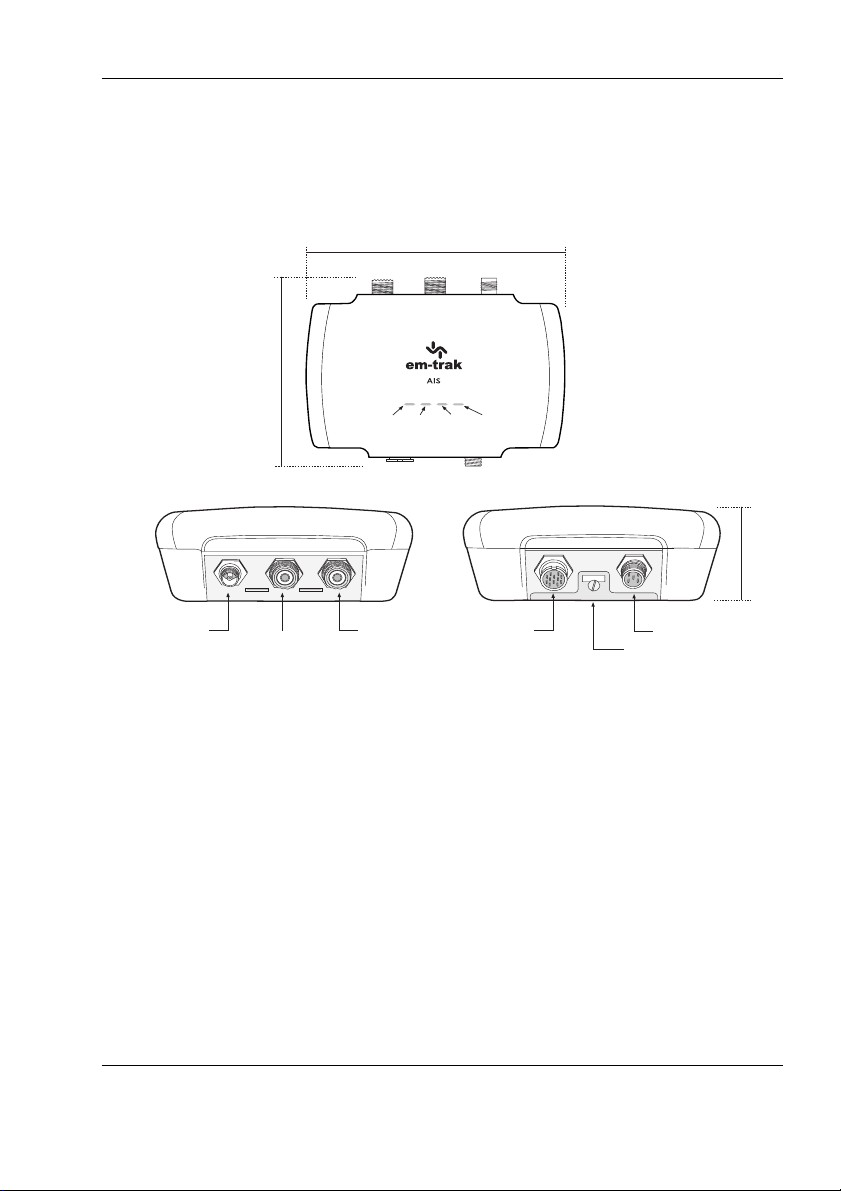
NMEA 2000Power and data
(Only applicable for
B923, B924, B953 and B954)
VHF antenna*GPS antenna
VHF radio
Mounting bracket
Amber
No Tx
indicator Lights
Blue
Silent
Red
Error
Amber
No Tx
Green
Power
* GPS receiver & antenna supports: GPS, GLONASS, Galileo and BeiDou
150 mm
115 mm
43 mm
2 About your AIS transceiver
2.1 Overview
Figure 1 AIS transceiver overview
Page 9
About your AIS transceiver
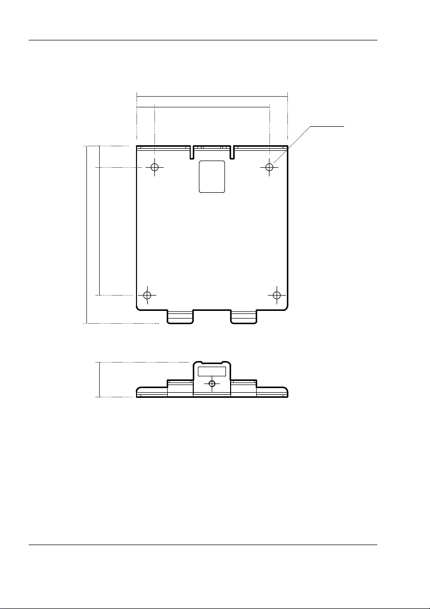
83.4 mm
60.3 mm 10 mm
71 mm
150 mm8.5 mm
3.4 mm DIA
60.3 mm
Figure 2 FLEXI-FIT bracket
Page 10

About your AIS transceiver
(IPx6 and IPx7)
Yes Yes Yes Yes Yes Yes Yes Yes
FLEXI-FIT bracket Yes Yes Yes Yes Yes Yes Yes Yes
Yes Yes Yes Yes Yes Yes Yes Yes
No No Yes Yes No No Yes Yes
WiFi & Bluetooth No Yes No Yes No Yes No Yes
r
No Yes No Yes No Yes No Yes
2.2 B900 Product range
The B900 Series provides multiple feature options. The variants are listed in
Table 3 and the main features are detailed below.
AIS Class B
transm iss ion type2WCSTDMA2WCSTDMA2WCSTDMA2WCSTDMA5WSOTDMA5WSOTDMA5WSOTDMA5WSOTDMA
Water & weatherproof
Integrated GNSS
receiver & antenna
Integrated VHF
antenna splitter
Voyage Data Recorde
NMEA 2000,
NMEA 0183 & USB
Table 1 Product variants
2.2.1 Main features:
● Integrated WiFi & Bluetooth so you can connect wirelessly to all your
devices. Only applicable to B922/B924/B952/B954.
● Integrated VHF antenna splitter so you can use your existing VHF
radio antenna. Only applicable to B923/B924/B953/B954.
● Integrated high performance GPS receiver and antenna so that an
external one is optional.
● FLEXI-FIT™ bracket to make installation on any boat simple, safe
and secure.
● IPx7 tested and certified for complete water submersion and IPx6
tested and certified for high pressure spray. The B900 Series is able
to be installed and operated permanently outdoors in a fully exposed
location or in a location where it will be exposed to extreme hot or
cold temperatures, damp, salt air and water.
● NMEA 2000, NMEA 0183 & USB so you can connect to any chart
plotter, sensor, PC or laptop.
B921 B922 B923 B924 B951 B952 B953 B954
Yes Yes Yes Yes Yes Yes Yes Yes
Page 11
About your AIS transceiver
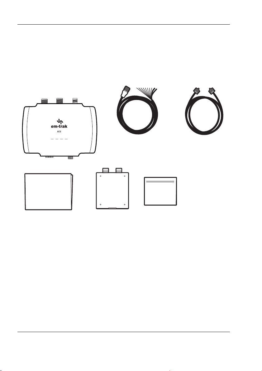
Documentation
pack
Class B AIS transceiver
2 metre
Power and
data cable
FLEXI-FIT
™
bracket
Fixings
kit
1 metre
VHF radio
connection cable
(only applicable
to B923 / B924 /
B953 / B954)
2.3 What's in the box?
Figure 3 shows the items included with your B900 Series purchase. If any of
the items are not present please contact your dealer or support@emtrak.com.
Figure 3 Items included with the product
2.4 Support and warranty
With em-trak you can buy with confidence. If you are unhappy with your new
product for any reason, within two days of receipt and subject to the product
and packaging being complete and undamaged, you may return it to us for a
full refund. We are sorry, but we cannot accept the return of any product if you
have not advised us in writing within 48 hours of receiving your em-trak
product, or if it has been used and or damaged or if any of the package is
incomplete. All em-trak products benefit from our three year global warranty.
In the unlikely event of a problem, please contact our Customer Support
department (24/7) at support@em-trak.com and one of our experts will work
Page 12

About your AIS transceiver
with you to instantly resolve your issue or arrange the repair or replacement
of your em-trak product. The warranty is invalidated if the product has been
incorrectly used, damaged or tampered.
We recommend visiting www.em-trak.com/support to access the product
FAQs, and to download user manuals and documentation.
2.5 Configuration tools
Your AIS transceiver will need to be configured with your vessel details before
it will start transmitting and working correctly. To do that you will need to
download the em-trak configuration tool on to your smartphone or PC,
whichever is most convenient for you.
If you wish to use your smartphone, you will need to download CONNECTAIS from Google Play or the Apple App Store.
.
Once downloaded you can configure the B922/B924/B952/B954 wirelessly
using either Bluetooth or WiFi connectivity. More detail on CONNECT-AIS
and the configuration process can be found in Section 3.5.2.
If you wish to use your PC or laptop, you will need to download proAIS2 from
www.em-trak.com/installation.
Once downloaded you can configure any variant using a micro USB cable
(not supplied). More detail on proAIS2 and the configuration process can be
found in Section 3.5.2.
Page 13
Installation
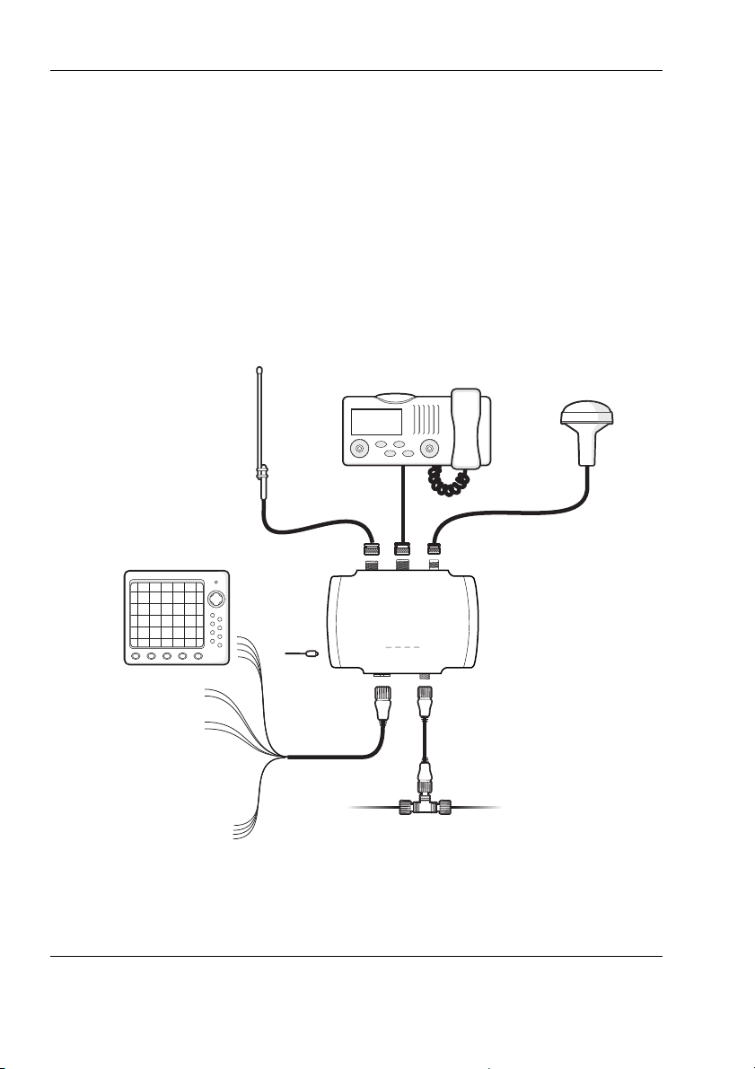
Power in
Switch
NMEA 2000
Chartplotter
VHF antenna
VHF radio
USB
NMEA 0183 device
GPS antenna
(Optional)
AIS Class B
transceiver
(Only applicable to B923, B924, B953 and B954)
3 Installation
3.1 Summary
Before beginning installation of your transceiver, please ensure you have any
necessary additional items as detailed below. It is strongly recommended that
you read all of the instructions in this manual prior to installation. If after
reading this manual you are unsure about any element of the installation
process please contact your dealer or support@em-trak.com for advice.
Figure 4 Typical installation configuration
Page 14

Installation
In addition to the items supplied, the following may also be required for your
installation:
● VHF antenna and cable - this is required for your transceiver to
receive and transmit. A variant with an integrated splitter (B923/
B924/B953/B954) can use an existing VHF antenna as long as it
covers 159MHz so it will be compatible with both VHF radio
(156MHz) and AIS (162MHz). VHF antenna installation is covered in
more detail in Section 3.2.1. If you need to extend the antenna cable
when connecting to your existing VHF antenna, RG-58 or RG-8X can
be used for short distances. For longer runs we would recommend a
low loss cable like RG-213.
● External GPS antenna - this may be required if your installation
location is deep inside your boat where the Integrated GPS receiver
and antenna will not be able to receive satellite signals. GPS antenna
installation is covered in more detail in Section 3.2.2.
● Power cable - this may be required to extend the length of the 2m
power and data cable that is supplied with your transceiver. If you
require longer cables to reach your power supply, please ensure they
are capable of carrying currents of up to 2.5A peak and 220mA on
average. Connecting the power supply is covered in more detail in
Section 3.3.1.
● Micro USB cable - this is required for connection to a PC or laptop.
USB drivers and the configuration process are covered in more detail
in Section 3.6.4.
● Toggle switch - this can be used to turn on/off silent mode. We would
recommend a latching toggle switch for this application. Installation of
the toggle switch is covered in more detail in Section 4.2. Silent mode
can also be controlled using the configuration tools, proAIS2 and
CONNECT-AIS.
Page 15
 Loading...