

Em-Trak B100 Product Manual

www.em-trak.com
Product Manual
HIGH PERFORMANCE
MARITIME
PRODUCTS
High Performance Maritime Products
em-trak B100
AIS Class B Transceiver

201-0137:1

Contents
1 - Notices ....................................................................................................................................1
1.1 - Safety warnings.....................................................................................................................1
1.2 - General notices .....................................................................................................................1
2 - About your AIS class B transceiver .....................................................................................4
2.1 - About AIS ..............................................................................................................................4
2.2 - Static and dynamic vessel data.............................................................................................4
2.3 - Important information for US customers................................................................................5
2.4 - What's in the box? .................................................................................................................6
3 - Installation ............................................................................................................................10
3.1 - Preparing for installation......................................................................................................10
3.2 - Installation procedures ........................................................................................................13
4 - Configuring your AIS transceiver .......................................................................................23
4.1 - Switching on your AIS transceiver for the first time.............................................................23
4.2 - Configuring your AIS transceiver.........................................................................................23
4.3 - Introduction to proAIS2........................................................................................................24
4.4 - Installing proAIS2 ................................................................................................................24
4.5 - Configuration using proAIS2 ...............................................................................................25
5 - Operation ..............................................................................................................................26
5.1 - Using the AIS transceiver....................................................................................................26
5.2 - Using a memory card ..........................................................................................................26
5.3 - Switch function ....................................................................................................................29
5.4 - Using proAIS2 with your AIS transceiver ............................................................................29
5.5 - Indicator functions ...............................................................................................................30
6 - Troubleshooting ...................................................................................................................32
7 - Specifications .......................................................................................................................33

Notices
Page 1
1 Notices
When reading this manual please pay attention to warnings marked with the warning
triangle shown on the left. These are important messages for safety, installation and
usage of the product.
1.1 Safety warnings
This equipment must be installed in accordance with the instructions provided in
this manual.
The em-trak B100 is an aid to navigation and must not be relied upon to provide
accurate navigation information. AIS is not a replacement for vigilant human
lookouts and other navigation aids such as Radar. The performance of the B100
may be seriously impaired if not installed as instructed in the user manual, or due
to other factors such as weather and or nearby transmitting devices. Compatibility
with other systems may vary and is reliant on the third party systems recognising
the standard outputs from the B100. em-trak reserves the right to update and
change these specifications at any time and without notice.
Do not install this equipment in a flammable atmosphere such as in an engine
room or near to fuel tanks.
1.2 General notices
Position source
All marine Automatic Identification System (AIS) transceivers utilise a satellite based location
system such as the Global Positioning Satellite (GPS) network.
The accuracy of a GPS position fix is variable and is affected by factors such as the antenna
positioning, how many satellites are used to determine a position and how long satellite
information has been received for.
Compass safe distance
The compass safe distance of this unit is 0.2m or greater for 0.3° deviation.
!
!
!
!

Notices
Page 2
RF emissions notice
Caution: The AIS transceiver generates and radiates radio frequency electromagnetic energy.
This equipment must be installed and operated according to the instructions contained in this
manual. Failure to do so can result in personal injury and / or AIS transceiver malfunction.
Caution: Never operate the AIS transceiver unless it is connected to a VHF antenna.
To maximise performance and minimise human exposure to radio frequency electromagnetic
energy you must make sure that the antenna is mounted at least 1.5 metres away from the AIS
transceiver and is connected to the AIS transceiver before power is applied. The system has a
Maximum Permissible Exposure (MPE) radius of 1.5m. This has been determined assuming the
maximum power of the AIS transceiver and using antennas with a maximum gain of 3dBi.The
antenna should be mounted 3.5m above the deck in order to meet RF exposure requirements.
Higher gain antennas will require a greater MPE radius. Do not operate the unit when anyone is
within the MPE radius of the antenna (unless they are shielded from the antenna field by a
grounded metallic barrier). The antenna should not be co-located or operated in conjunction with
any other transmitting antenna. The required antenna impedance is 50 Ohms.
Warranty
This product is supplied with standard warranty as defined in the accompanying warranty
information.
Any attempt to tamper with or damage this product will invalidate the warranty.
Disposal of this product and packaging
Please dispose of the AIS transceiver in accordance with the European WEEE Directive or with
the applicable local regulations for disposal of electrical equipment.
Every effort has been made to ensure the packaging for this product is recyclable. Please
dispose of the packaging in an environmentally friendly manner.
Accuracy of this manual
The AIS transceiver may be upgraded from time to time and future versions of the AIS
transceiver may therefore not correspond exactly with this manual. Information contained in this
manual is liable to change without notice. The manufacturer of this product disclaims any liability
!

Notices
Page 3
for consequences arising from omissions or inaccuracies in this manual and any other
documentation provided with this product.
Declaration of conformity
The manufacturer of this product declares that this product is in compliance with the essential
requirements and other provisions of the R&TTE directive 1995/5/EC.
The product carries the CE mark, notified body number and alert symbol as required by the
R&TTE directive.
The product is intended for sale in the following member states: Great Britain, France, Spain,
Sweden, Austria, Netherlands, Portugal, Denmark, Norway, Belgium, Italy, Finland, Ireland,
Luxembourg, Germany, Czech Republic.
FCC notice
This equipment has been tested and found to comply with the limits for a class B digital device,
pursuant to part 15 of the FCC Rules. These limits are designed to provide reasonable protection
against harmful interference in a residential installation.
This equipment generates, uses and can radiate radio frequency energy and, if not installed and
used in accordance with the instructions, may cause harmful interference to radio
communications.
This device complies with part 15 of the FCC Rules. Operation is subject to the following two
conditions: (1) This device may not cause harmful interference, and (2) this device must accept
any interference received, including interference that may cause undesired operation.
Changes or modifications not expressly approved by the party responsible for compliance could
void the user's authority to operate the equipment.
WARNING: It is a violation of the rules of the Federal Communications
Commission to input an MMSI that has not been properly assigned to the end
user, or to otherwise input any inaccurate data in this device.
Industry Canada notice
This AIS class B digital apparatus complies with Canadian ICES-003.
Cet appareil numérique de la AIS classe B est conforme à la norme NMB-003 du Canada.
!

About your AIS class B transceiver
Page 4
2 About your AIS class B transceiver
2.1 About AIS
The marine Automatic Identification System (AIS) is a location and vessel information reporting
system. It allows vessels equipped with AIS to automatically and dynamically share and regularly
update their position, speed, course and other information such as vessel identity with similarly
equipped vessels. Position is derived from the Global Positioning System (GPS) and
communication between vessels is by Very High Frequency (VHF) digital transmissions.
There are a number of types of AIS device as follows:
• Class A transceivers. These are similar to class B transceiver, but are designed to be fitted
to large vessels such as cargo ships and large passenger vessels. Class A transceivers
transmit at a higher VHF signal power than class B transceivers and therefore can be
received by more distant vessels, and also transmits more frequently. Class A transceivers
are mandatory on all vessels over 300 gross tonnes on international voyages and certain
types of passenger vessels under the SOLAS mandate.
• Class B transceivers. Similar to class A transceivers in many ways, but are normally lower
cost due to the less stringent performance requirements. Class B transceivers transmit at a
lower power and at a lower reporting rate than class A transceivers.
• AIS base stations. AIS base stations are used by Vessel Traffic Systems to monitor and
control the transmissions of AIS transceivers.
• Aids to Navigation (AtoN) transceivers. AtoNs are transceivers mounted on buoys or
other hazards to shipping which transmit details of their location to the surrounding vessels.
• AIS receivers. AIS receivers will generally receive transmissions from class A transceivers,
class B transceivers, AtoNs and AIS base stations but do not transmit any information about
the vessel on which they are installed.
The em-trak B100 is an AIS class B transceiver.
2.2 Static and dynamic vessel data
There are two categories of information transmitted by an AIS transceiver: static and dynamic
data.
The vessel's dynamic data, which includes location, speed over ground (SOG) and course over
ground (COG), is calculated automatically using the internal GPS receiver.

About your AIS class B transceiver
Page 5
Static data is information about the vessel which must be programmed into the AIS transceiver.
This includes:
• Maritime Mobile Service Identity (MMSI)
•Vessel name
• Vessel call sign (if available)
• Vessel type
• Vessel dimensions
In most countries the operation of an AIS transceiver is included under the vessel's marine VHF
licence provisions. The vessel on to which the AIS unit is to be installed must therefore possess a
current VHF radiotelephone licence which lists the AIS system, vessel Call Sign and MMSI
number.
An MMSI number is required in order for the AIS transceiver to operate. Please
contact the relevant authority in your country for more information.
2.3 Important information for US customers
There are specific laws in the USA regarding the configuration of AIS class B transceivers.
If you are a US resident and intend to use your AIS class B transceiver in US waters, you should
make sure that your retailer has configured your product prior to supplying it to you. If your AIS
transceiver has not been pre-configured please contact your dealer for details of how to have it
configured.
Alternatively, if you have received a configuration card for your AIS transceiver you may
configure the AIS transceiver by following the instructions provided with the card.
!
About your AIS class B transceiver
Page 6
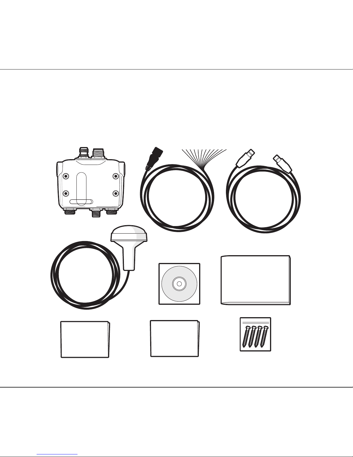
2.4 What's in the box?
Figure 1 shows the items included with your AIS transceiver purchase. The following sections
give a brief overview of each item. Please ensure all items are present and if any of the items are
not present contact your dealer.
Figure 1 Items included in the product
Screws (packet of 4)
Product CD
Quick
start guide
Product manual
GPS Antenna
Class B AIS transceiver
Power and data cable
USB cable
Warranty
information

About your AIS class B transceiver
Page 7
Items included in the box:
• Support tools CD
The CD supplied with the package contains the following:
- proAIS2 software tool necessary to configure the AIS transceiver. Please refer to section
4 for details of the configuration process and how to use the proAIS2 tool.
- USB drivers required to connect to the AIS transceiver via USB.
- Alternative language versions of this manual.
- Other application software may be included on the CD depending on the version of
product you have purchased. For details of AIS application softwar please contact emtrak via the details printed on the back of this manual.
• Quick start guide
The quick start guide gives a handy one page reference for the installation process.
• Product manual
This document is the product manual and should be read thoroughly prior to any attempt to install
or use the AIS transceiver.
• GPS antenna
The GPS antenna forms an integral part of the product's internal positioning system based on
GPS. Please refer to section 3.2 for details of how to install the GPS antenna.
• Fixing screws
Four fixing screws are provided with the product for mounting of the AIS transceiver. Please
refer to section 3.2 for details of how to mount the AIS transceiver.
• Power and data cable
The power and data cable connects to the AIS transceiver and enables connection to power,
NMEA0183 and an external switch.
• USB cable
The USB cable enables connection toa PC for configuration purposes.
• AIS transceiver unit
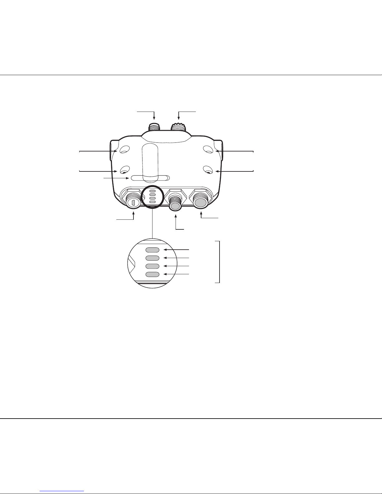
Figure 2 shows an overview of the AIS transceiver unit. The AIS transceiver has a number of
indicators which provide information to the user about the status of the AIS transceiver. Please
refer to section 5.5 for more details of indicator functions.
About your AIS class B transceiver
Page 8
Figure 2 AIS transceiver overview
Electrical connections
The AIS transceiver has the following electrical connections:
• Power supply
• Two independent NMEA0183 data port for connection to chart plotters and other NMEA0183
compatible equipment
• USB for connection to a PC
• External switch input
• NMEA2000 port for connection to NMEA2000 compatible equipment
• Memory card slot
VHF antenna connector
Power and data
NMEA 2000
GPS antenna connector
USB connector
Mounting
holes
Mounting
holes
Green
Amber
Red
Blue
Indicator
lights
Memory card slot

About your AIS class B transceiver
Page 9
In addition there are two other connections for the GPS antenna and the VHF antenna. Figure 3
shows an overview of the electrical connections to the AIS transceiver.
Figure 3 Electrical connections to the AIS transceiver
Chartplotter
NMEA0183
device
Switch Power in
NMEA 2000
USB
Class B AIS transceiver
 Loading...