


M a n u a l
F o r O p e r a t i o n
UCS 500Nx
The ultra-compact simulator
and its system modules
UCS 500 N5
UCS 500 N7
Modules for Telecom surge
Tsurge5 / Tsurge7
CNT 508 / CNT 516
V 4780 / V4780 S1
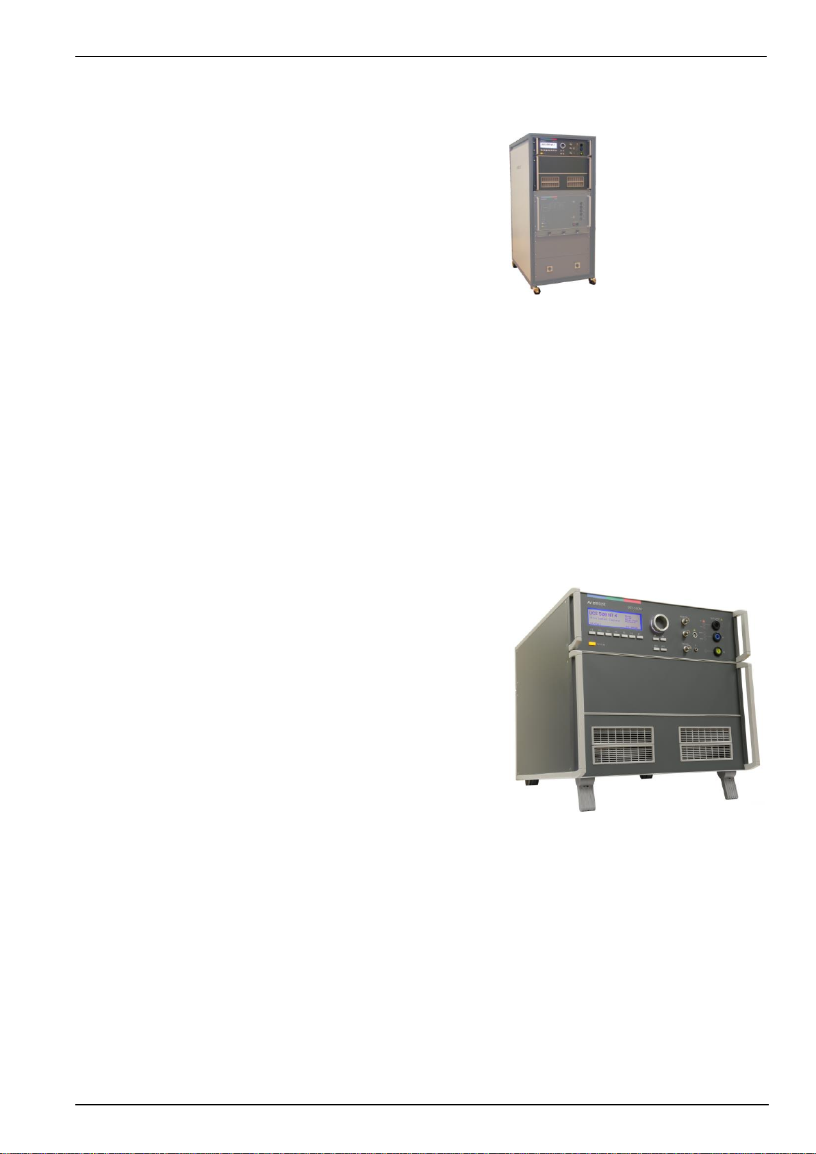
UCS500Nx - designed as a modular system - is the most
intelligent solution offering exactly what you need for fullcompliant immunity tests against transient and power fail
phenomena. The distinct operation features, convenient DUT
connection facilities, a clearly arranged menu structure and
display philosophy as well as the pre-programmed standard test
routines make testing easy, reliable and safe. Extendable by a
variety of test accessories the UCS 500Nx is a universal
equipment for abroad range of recommendations even for threephase applications up to 100A
EN/IEC 61000-4-4
EN/IEC 61000-4-5
EN/IEC 61000-4-8
EN/IEC 61000-4-9
EN/IEC 61000-4-11
EN/IEC 61000-4-12
EN/IEC 61000-4-29
EN 61000-6-1
EN 61000-6-2
Version:
5.40 / 13.12.2016
the benchmark for emc
Replaces:
5.39 / 03.08.2016
Filename:
UserManual-UCS 500N5-7-E-V5.40.doc
Printdate:
13.12.16

EM TEST UCS 500 Series
Operating Manual V 5.40 2 / 99
EM Test (Switzerland) GmbH
Sternenhofstrasse 15
4153 Reinach BL1
Switzerland
Phone : +41 61 717 91 91
Fax : +41 61 717 91 99
URL : http://www.emtest.com
Copyright © 2016 EM Test (Switzerland) GmbH
All right reserved.
Information in earlier versions. Specifications subject to change

EM TEST UCS 500 Series
Operating Manual V 5.40 3 / 99
Contents
1. Model Overview ............................................................................................................... 6
1.1. UCS Models........................................................................................................................................ 6
1.2. Standards covered by UCS N Series ................................................................................................. 8
2. Safety information ........................................................................................................... 9
2.1. Protected Earth PE ............................................................................................................................. 9
2.2. FI Fault current protection .................................................................................................................. 9
3. Operating Functions ..................................................................................................... 10
3.1. Front view ......................................................................................................................................... 10
3.2. Rear view .......................................................................................................................................... 12
4. Operation ....................................................................................................................... 15
4.1. Description of the menus .................................................................................................................. 15
4.2. Menu structure .................................................................................................................................. 15
4.3. Main Menu ........................................................................................................................................ 16
4.4. Service .............................................................................................................................................. 17
4.5. Setup ................................................................................................................................................ 19
4.6. Setup procedure for Set voltage ....................................................................................................... 21
5. Test Equipment UCS 500N ........................................................................................... 22
5.1. UCS 500 N5...................................................................................................................................... 22
5.2. UCS 500 N7...................................................................................................................................... 23
6. Technical data ............................................................................................................... 24
6.1. EFT Electrical Fast Transients Burst as per IEC 61000-4-4 ............................................................... 24
6.2. SURGE Immunity requirements as per IEC 61000-4-5 ................................................................... 25
6.3. Power Fail Generator as per IEC 61000-4-11 .................................................................................. 26
6.4. RINGWAVE Immunity requirements as per IEC 61000-4-12 ........................................................... 27
6.5. Telecom Surge Generator as per IEC 61000-4-5 (TSurge module) ................................................ 28
6.6. EUT Supply Specifications ............................................................................................................... 29
6.7. General Specifications ...................................................................................................................... 30
6.8. Environmental conditions ................................................................................................................. 30
6.9. Technical data of special generators ................................................................................................ 31
6.9.1. UCS 500N5.2T ................................................................................................................................. 31
6.9.2. UCS 500N5.5 and UCS 500N5.6 and UCS 500N5.9 for Railways application ................................ 32
6.9.3. UCS 500N5.11 ................................................................................................................................. 33
6.9.4. UCS 500N6.5.................................................................................................................................... 34
6.9.5. UCS 500N6.7.................................................................................................................................... 34
6.9.6. UCS 500N7.1.................................................................................................................................... 35
6.9.7. UCS 500N7.4.................................................................................................................................... 35
7. Maintenance setup and service ................................................................................... 36
7.1. General ............................................................................................................................................. 36
7.2. Test set- up ....................................................................................................................................... 36
7.3. Fuse for the EUT power supply ........................................................................................................ 36
7.4. Insulating- or external transformer for EUT power supply ................................................................ 36
7.5. Calibration and verification ............................................................................................................... 37
7.5.1. Factory calibration ............................................................................................................................ 37
7.5.2. Guideline to determine the calibration period of EM Test instrumentation ...................................... 37
7.5.3. Calibration of Accessories made by passive components only: ...................................................... 37
7.5.4. Periodically In-house verification ...................................................................................................... 37
8. Delivery Groups ............................................................................................................. 38
8.1. Basic equipment ............................................................................................................................... 38
8.2. Accessories and options ................................................................................................................... 38

EM TEST UCS 500 Series
Operating Manual V 5.40 4 / 99
9. EFT Burst as per IEC 61000-4-4 .................................................................................. 40
9.1. Operation .......................................................................................................................................... 40
9.1.1. Quick Start ........................................................................................................................................ 41
9.1.2. Standard test routines ..................................................................................................................... 42
9.1.3. User Test Routines ........................................................................................................................... 43
9.2. Burst generation ............................................................................................................................... 45
9.3. Test level with Burst as per IEC 61000-4-4 Ed.2. ............................................................................ 45
9.4. Coupling/decoupling network ........................................................................................................... 46
9.4.1. Coupling/decoupling network for ac/dc power lines ......................................................................... 46
9.4.2. Capacitive coupling clamp ................................................................................................................ 46
9.5. Burst Test Setup ............................................................................................................................... 46
9.5.1. Test setup with capacitive coupling clamp ....................................................................................... 47
10. Surge Immunity as per IEC 61000-4-5 ......................................................................... 48
10.1. Operation .......................................................................................................................................... 48
10.1.1. Quick Start ........................................................................................................................................ 49
10.1.2. Standard test Routine ....................................................................................................................... 50
10.1.3. User Test Routines ........................................................................................................................... 52
10.1.4. Phase synchronization in 3-phase system ....................................................................................... 54
10.1.5. Pulsed magnetic field as per IEC 61000-4-9 .................................................................................... 56
10.1.6. Setup current limiter for surge current .............................................................................................. 57
10.1.7. Charging time for surge .................................................................................................................... 58
10.2. Surge pulse generation .................................................................................................................... 59
10.3. Coupling/decoupling network ........................................................................................................... 59
10.3.1. Coupling to ac/dc power supply lines ............................................................................................... 59
10.3.2. Coupling to I / O lines ....................................................................................................................... 60
10.4. Test set-up ........................................................................................................................................ 60
11. Voltage Dips as per IEC 61000-4-11 ............................................................................. 61
11.1. Test setup for DIPS and Interruption tests ....................................................................................... 61
11.2. Operation .......................................................................................................................................... 61
11.2.1. Quick Start ........................................................................................................................................ 62
11.2.2. Standard Test Routines .................................................................................................................... 63
11.2.3. User Test Routines ........................................................................................................................... 67
11.3. The Power Fail Test ......................................................................................................................... 68
11.4. Overcurrent ....................................................................................................................................... 69
11.5. The Power Fail Test ......................................................................................................................... 70
11.5.1. Voltage Interruptions ........................................................................................................................ 70
11.5.2. Voltage dips, voltage variations ........................................................................................................ 71
11.6. DC Power networks .......................................................................................................................... 71
11.7. Test setup and accessories .............................................................................................................. 72
11.7.1. Transformer type V4780 ................................................................................................................... 72
11.7.2. Motor variac type MV 2616 ............................................................................................................... 74
11.8. 50/60Hz Magnetic Field as per IEC 61000-4-8 ................................................................................ 76
12. Ringwave Immunity as per IEC 61000-4-12 ................................................................. 78
12.1. Operation .......................................................................................................................................... 78
12.1.1. Quick Start ........................................................................................................................................ 78
12.2. Ring wave pulse generation ............................................................................................................. 80
12.3. Coupling/decoupling network ........................................................................................................... 80
12.3.1. Coupling to ac/dc power supply lines ............................................................................................... 80
12.4. Test set-up ........................................................................................................................................ 80
13. Telecom Surge ............................................................................................................... 81
13.1. UCS 500N5T with Telecom Surge Module ...................................................................................... 81
13.2. TSurge7 Module ............................................................................................................................... 81
13.3. TSurge7 Module ............................................................................................................................... 81
13.4. TSurge Menu .................................................................................................................................... 82
13.4.1. Quick Start ........................................................................................................................................ 82
13.5. Coupling Network ............................................................................................................................. 83
13.6. Test Setup ........................................................................................................................................ 84
13.7. Test pulses TSurge Modules ............................................................................................................ 84
13.7.1. Waveshape Definitions according IEC 61000-4-5 Ed 3.0 ................................................................ 84
13.7.2. Pulse 10 / 700s as per IEC 61000-4-5 ........................................................................................... 85
13.7.3. Pulse 9 / 720s as per FCC ............................................................................................................. 85

EM TEST UCS 500 Series
Operating Manual V 5.40 5 / 99
14. Appendix ........................................................................................................................ 86
14.1. Declaration of CE-Conformity ........................................................................................................... 86
14.1.1. Declaration of Conformity UCS 500N5 ............................................................................................. 86
14.1.2. Declaration of Conformity UCS 500N7 ............................................................................................. 87
14.1.3. Declaration of Conformity UCS 500N5x models for one phenomenon ............................................ 88
14.1.4. Declaration of Conformity UCS 500N5x models .............................................................................. 89
14.1.5. Declaration of Conformity TSurge 7 Module for UCS 500N7 ........................................................... 90
14.1.6. Declaration of Conformity CNT 516.................................................................................................. 91
14.1.7. Declaration of Conformity Tapped Transformer ............................................................................... 92
14.2. UCS 500N - General Diagram .......................................................................................................... 93
14.3. Main diagram control connection...................................................................................................... 93
14.4. Main diagram high voltage connection ............................................................................................. 94
14.5. CNT 508N ......................................................................................................................................... 95
14.6. CNT 516 ........................................................................................................................................... 97
14.7. USB interface.................................................................................................................................... 99

EM TEST UCS 500 Series
Operating Manual V 5.40 6 / 99
1.
Model Overview
The following manual is based on the following or later firmware:
- UCS 500N5 : V 5.00xx
- UCS 500N7 : V 8.00xx
- UCS 500N7 : V 9.00xx Supports ANSI A/B coupling method. Requires iec.control V 5.2.3.0 or higher
Devices with the Firmware
- UCS 500N5 : V 4.40uxx
- UCS 500N7 : V 7.40uxx
Have a reduced PFS function of the PFS module. For UCS generators with this firmware version exist a separate
manual with the version 5.09. This manual can be ordered at EM TEST if required.
1.1.
UCS Models
Standard models
Model
U pulse
CDN
Remarks
UCS 500N5
5.5kV
300V 16A 1- ph
UCS 500N5.1
5.5 kV
300V 32A 1- ph
Optional + Tsurge 6HU
UCS 500N5T
5.5 kV
300V 16A 1- ph
EFT, Surge, PFS, TSurge 6HU
UCS 500N5.1T
5.5 kV
300V 32A 1- ph
EFT, Surge, PFS, TSurge 6HU
UCS 500N7
7kV
300V 16A 1- ph
DC 300V / 16A ANSI
UCS 500N7.1
7kV
300V 32A 1- ph
DC 300V / 32A ANSI 9HU
Additional extensions
TSurge5
4kV
Built-in 10/700us pulse module up to 5kV, ITU K22 & IEC 61000-4-5
TSurge7
6kV
External 10/700us pulse module up to 7kV, ITU K22 & IEC 61000-4-5
UCS500N with one built in module
The device includes only one module Surge, Burst or Power Fail. The technical data are identical with the
standard UCS500N5. An extension with additional modules is not possible.
UCS500N5V
5kV
UCS500 with Surge Module
UCS500N5E
5.5kV
UCS500 with EFT Burst Module
UCS500N5P
--
UCS500 with Power Fail Module
Module for UCS500N7
Module
Remarks
EFT/N7
Built-in 5.5kV BURST MODULE
VCS/N7
Built-in 7.0kV SURGE MODULE
PFS/N7
Built-in POWER FAIL MODULE 300 volts/ 16 amps. Mandatory for EUT power switch off
RWG/N7
Built-in Ring Wave Module 6 kV / 100 kHz, Ri =12/30 Ω as per ANSI
(not available for UCS 500N7.1 or UCS 500N7.2)
RWG/N7.1
Built-in Ring Wave Module 6 kV / 100 kHz, Ri =12/30/50 Ω as per ANSI / UL 1741,
No peak current measurement (display indicates = ---).
(not available for UCS 500N7.1 or UCS 500N7.2)
TSurge7
External 10/700us pulse module up to 7.0kV, ITU K22 & IEC 61000-4-5

EM TEST UCS 500 Series
Operating Manual V 5.40 7 / 99
Special models
Model
V
Pulse
CDN
Remarks
UCS 500N5.2
5.5kV
400V 16A 1- ph
UCS 500N5.2T
5.5kV
300V 16A 1- ph
UCS 500 with VCS/5 and Telecom Surge module
UCS 500N5.3
5.5 kV
400V 32A 1- ph
UCS 500N5.3-PFS
5.5 kV
400V 32A 1- ph
UCS500 with Power Fail module 400V AC 32A (L-N)
UCS 500N5.4
5.5kV
300V 16A 1- ph
DC 300V 16A
UCS 500N5.5
5.5 kV
300V 32A 1- ph
EFT/5 and VCS/5
10/40 for supply lines EN 50121-3-2:2007 (Railway)
UCS 500N5.6
5.5 kV
300V 32A 1- ph
EFT/5 VCS/5 and PFS/5
10/40 for supply lines EN 50121-3-2:2007 (Railway)
UCS 500N5.7
5.5kV
300V 16A 1- ph
EFT/5 and VCS/5
UCS 500N5.8
5.5kV
300V 16A 1- ph
EFT/5 and PFS/5; 1ph CDN 300V/16A
UCS 500N5.9
5.5 kV
300V 16A 1- ph
10 /40 for supply lines EN 55121 (Railway)
UCS 500N5.10
5.5kV
690V 16A 1- ph
VCS/5 without built-in coupler
UCS 500N5.11
5.5kV
690V 16A 1- ph
EFT/5, VCS/5 / Tsurge
UCS 500N7.2
7kV
400V 16A 1- ph
EFT/N7, VCS/N7, PFS/N7 (ANSI)
UCS 500N7.3
7kV
300V 16A 1- ph
EFT/N7, VCS/N7, PFS/N7 (ANSI), RWG/N7.x
UCS 500N7.4
7kV
400V 16A 1- ph
EFT/N7, VCS/N7, PFS/N7, (ANSI), RWG/N7.x
UCS 500N7.6
7kV
690V 16A 1- ph
EFT/N7, VCS/N7.x, RWG/N7, without built-in coupler! AC Voltage 690V
UCS 500N7.7
7kV
690V
EFT/N7, VCS/N7.x, without built-in coupler! AC Voltage 690V(p-p)
UCS 500N7.8
7kV
400V 16A 1- ph
EFT/N7, RWG/N7.x (output impedance 12 and 25 ohm); (ANSI)
UCS 500N7.9
7kV
690V
EFT/N7, VCS/N7, RWG/7.x (Ri 12Ω & 50Ω), no built-in coupler, 690V(p-p)
UCS 500N7.10
7kV
690V
VCS/7, no built-in coupler! Application Voltage 690V(p-p)
Other models up to 2009
Model
Name up to 2008
Pulse voltage
CDN
UCS 500 N4.1
UCS 500 M4 S1
4kV
250V 32A single phase
UCS 500 N6
UCS 500 M6B
6kV
250V 16A single phase
UCS 500 N6.1
--
6kV
250V 32A single phase
UCS 500 N6.3
--
6kV
480V 32A single phase
Models up to 2008
Model Pulse voltage
CDN
UCS 500 4kV
250V 16A single phase
upgrade version
UCS 500 M4 4kV
250V 16A single phase
UCS 500 M6 6kV
250V 16A single phase
UCS 500 M6A 6kV
250V 16A single phase

EM TEST UCS 500 Series
Operating Manual V 5.40 8 / 99
Special models
Special models have the index UCS500Nx Sx. The difference to the standard models are: Voltage- and current
ranges. The operation is the same as by the standard UCS equipment’s.
Model Pulse voltage
CDN
UCS 500 M4 S1 4kV
250V 32A single phase
UCS 500 M4 S2 4kV
690V 16A single phase
UCS 500 M4 S3 4kV
690V 32A single phase
UCS 500 M4 S5 4kV
280V 16A single phase
UCS 500 M6 S2 6kV
690V 16A single phase
ANSI
Model
Pulse EUT
Modules
UCS 500 M6B S1
6kV 250V 32A
EFT/6, VCS/6 and PFS/6; 1ph CDN 250V / 32A (ANSI)
module RWG/6 not available
UCS 500 M6B S2
6kV 690V 16A
EFT/6, VCS/6 and PFS/6; 1ph CDN 690V / 16A (ANSI) 480V dc
module RWG/6 not available
1.2.
Standards covered by UCS N Series
A fully equipped UCS 500N covers the following standards
UCS 500
N5
N7
- IEC 61000-4-4
Burst
X
X
- IEC 61000-4-5
Surge
X
X
- IEC 61000-4-8
50/60Hz Magnetic Field
X
X
- IEC 61000-4-9
Pulse Magnetic Field
X
X
- IEC 61000-4-11
Voltage Dips
Voltage Interruptions
Voltage Variations for ac power mains supply
X
X
- IEC 61000-4-12
Ringwave
X
- IEC 61000-4-29
Voltage Interruptions
Voltage Dips for dc power supply systems
X
X
- ANSI
Surge with 2 coupling
X
- ITU and ETS
Telecom Surge
(X)
(X)
- FCC
Part 68
(X)
(X)
EM TEST UCS 500 Series
Operating Manual V 5.40 9 / 99
2.
Safety information
Attention
Before using this equipment, read the operating manual and the
separate delivered safety manual carefully
2.1.
Protected Earth PE
The protective conductor connection is established via the attached power cord and must not be interrupted
under any circumstances.
DANGER
Check before connecting the power supply to the unit that the grounding of the building supply is
installed according to regulations.
In the absence of an earth connection can the frame can be get in the event of a fault, to the mains
voltage potential.
The generator must be properly grounded before connecting on-the EUT supply voltage to the
generator.
2.2.
FI Fault current protection
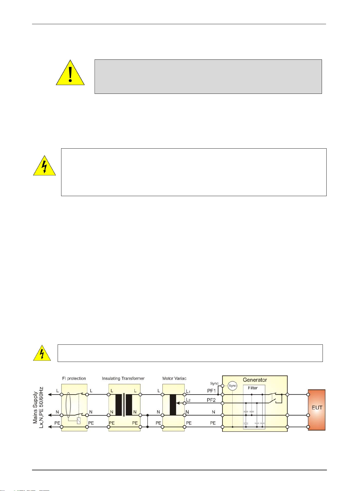
The standards recommend decoupling and filter capacitors to PE for decoupling surge pulses. This is the reason
for tripping fault current protection relays interrupt the mains to the EUT supply. For eliminate the circumstance
use one of the following options:
Remove the fault current protection
This solution does not limit the current to PE. The surge test as other EMC tests with higher currents to PE are
possible. The user must take care to the circuit with no fault current protection. Only trained professional people
are allowed to perform such tests.
Using of insulating transformers
An insulating transformer separates the circuit from the test circuit. The Fault current detector cannot detect the
earth current in the EUT circuit. The synchronization works between line and PE and therefore a connection
between neutral and PE is necessary. Without this N-PE connection the stray capacitance defines the phase
sync.
The fault current safety detection function in the generator circuit is disabled. The user must respect
this circumstance. For a safe operation he must follow the electrical rulers.
Behind the insulating transformer the neutral and PE must be connected for a proper phase synchronization of
the generator. In case of a 3-phase system the user must perform similar.
EM TEST UCS 500 Series
Operating Manual V 5.40 10 / 99
3.
Operating Functions
3.1.
Front view
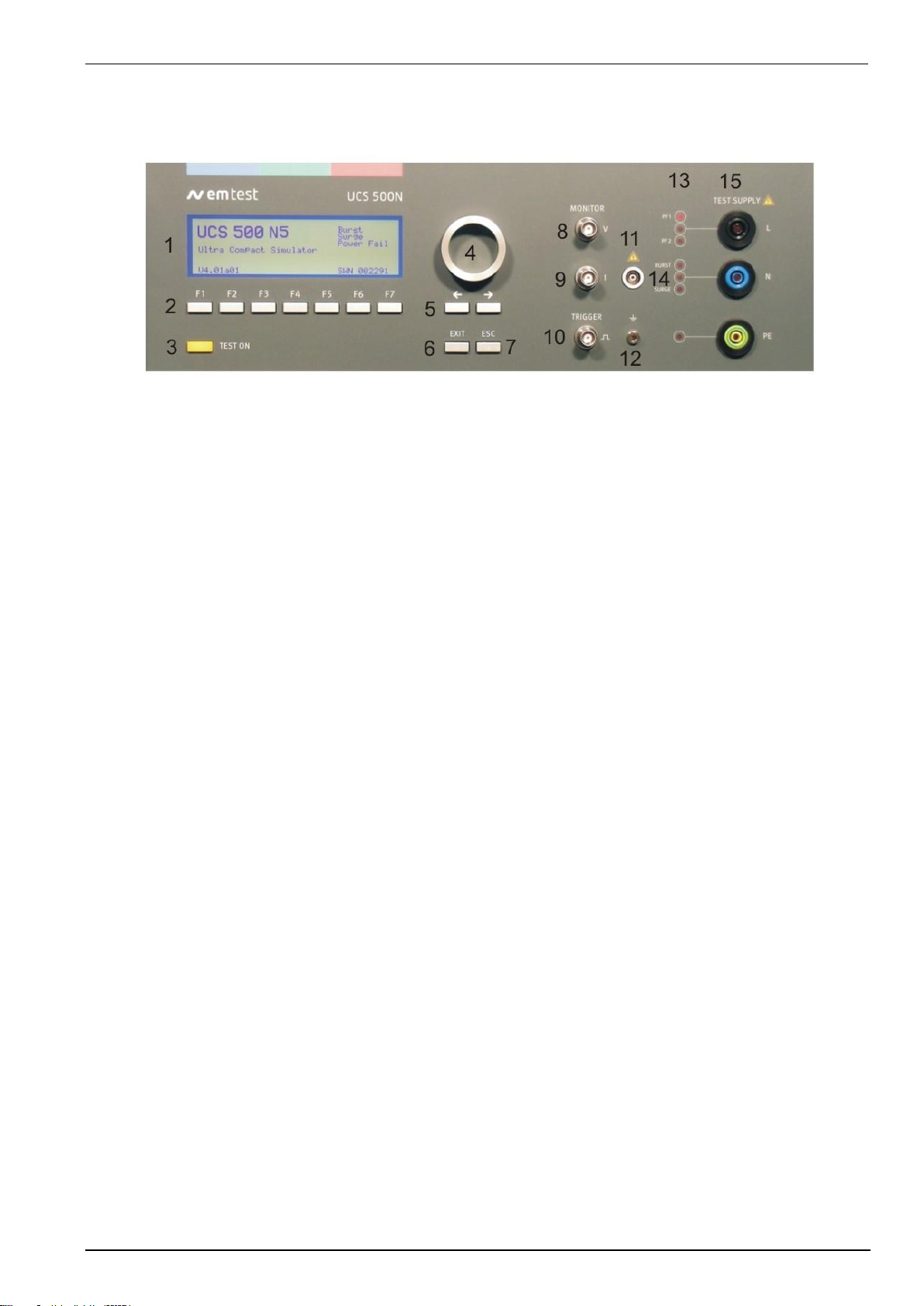
1 Display
2 Function keys "F1..F7
3 "Test On"
4 Knob (Inc. / Dec
5 Cursor keys "" and ""
6 Exit
7 Escape
8 CRO U (surge)
9 CRO I (surge)
10 CRO Trigger output 5V
11 HV pulse Burst output 50
12 Ground reference
13 Coupling (Burst, Surge and EFT)
14 Channel PF1 and PF2
15 EUT test supply
1 Display
All functions and parameters are displayed (8 lines with max. 40 characters).
2 Function keys "F1 .. F7”
Parameters and functions, displayed in the lowest line, can be selected with the related function key.
3 Test On
By pressing the key "Test On" follows the functions:
- Activate the high voltage power unit; HV is ready to start.
- Switches ON the supply to the EUT test supply (only with built in PFS module).
- The LED indicates the trigger of a burst event.
4 Knob (Inc. / Dec
The knob increments or decrements test parameters with a numeric value or selects from a list of parameters.
5 Cursor keys
Parameters and functions can be changed on-line. The selection of these parameters is realized with the cursor
moving to the left or to the right.
6 Exit
Pressing of the Exit function will cause a reset of the firmware. This is only possible if no test routine is running.
7 ESC
When pressing the ESC button the user moves back one page in the menu.
8 CRO U (surge)
At the BNC output the voltage pulse (surge) of the generator can be measured galvanic separated.
- Impedance measuring instrument: >1MΩ.
- Max. output voltage: 10V 10% at 5 kV / 7kV impulse voltage.
9 CRO I (surge)
At the BNC output the current pulse (surge) of the generator can be measured galvanic separated.
- Impedance measuring instrument: >1MΩ.
- Max. output voltage: 10V 10% at 2.5 kA / 3.5kA output current.
10 BNC - CRO Trigger
At the BNC output the generator trigger can be checked, e.g. the burst duration, the burst repetition rate and the
spike frequency (+5 V rectangular). This output can be generally used as oscilloscope trigger output and is
synchronous to the following events.
- Burst and surge release
- Voltage dip or interruption, start of the event

EM TEST UCS 500 Series
Operating Manual V 5.40 11 / 99
1 Display
2 Function keys "F1..F7
3 "Test On"
4 Knob (Inc. / Dec
5 Cursor keys "" and ""
6 Exit
7 Escape
8 CRO U (surge)
9 CRO I (surge)
10 CRO Trigger output 5V
11 HV pulse Burst output 50
12 Ground reference
13 Coupling (Burst, Surge and EFT)
14 Channel PF1 and PF2
15 EUT test supply
11 HV pulse burst output 50
External coupling devices such as the capacitive coupling clamp and the 3-phase coupling network are
connected to the coaxial 50 ohm output. Also the calibration of the generator is handled at this output.
Note: The burst signal is present on this output at every coupling mode.
12 Ground reference
During test or calibration procedure the burst generator must be grounded to the reference ground plane
13 Coupling mode
The actual coupling mode is indicated by LED
14 Channel PF1/PF2
This LED indicates the channel mode during the power fail test.
15 EUT test supply
For single-phase EUT the coupling/decoupling network is part of the generator. The EUT is powered via the
safety banana plugs at the front panel of the simulator.
EM TEST UCS 500 Series
Operating Manual V 5.40 12 / 99
3.2.
Rear view
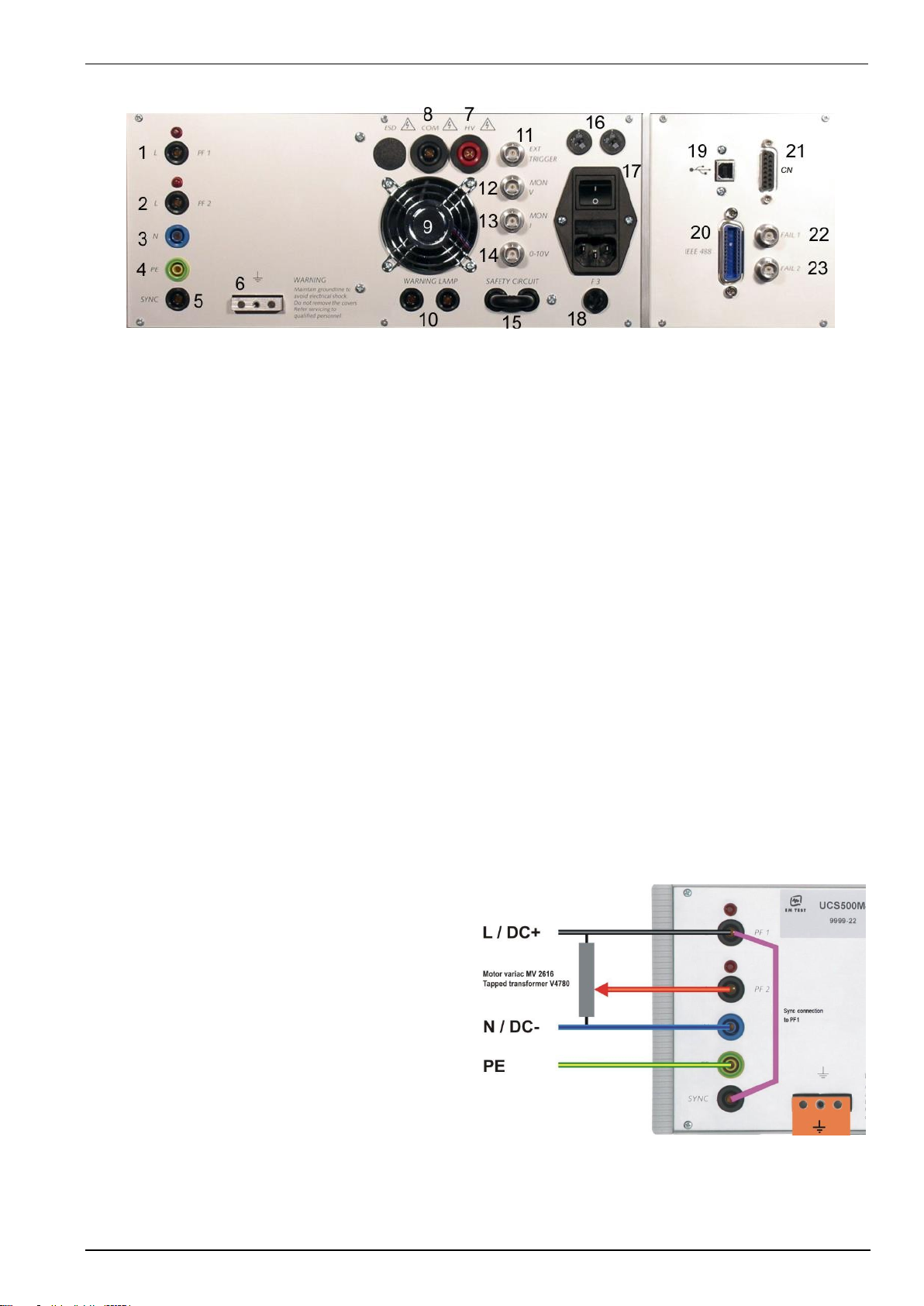
1 Test supply input; channel PF1 together with
the red lamp for phase indication
2 Test supply input; channel PF2 together with
the red lamp for phase indication
3 Test supply input neutral
4 Test supply input PE
5 Sync input
1 Test supply PF1
The phase of the power supply for the EUT is connected to the banana connector PF1. The phase L is
conducted to the EUT voltage supply via PF1 if channel PF1 is selected in the set-up menu.
To guarantee a correct function of the synchronization the phase shall be connected to this input. The red lamp
than shall be alighted.
2 Test supply PF2
This input is generally used for the reduced dip voltage for testing as per IEC 61000-4-11. At this PF2 input a
variac transformer is connected with a reduced voltage, e.g., 0-250V. A motor driven variac transformer can be
controlled via a 0-10V analogue control output.
To guarantee a correct function of the synchronization the phase shall be connected to this input. The red lamp
than shall be alighted.
3 Test supply neutral (PF1/PF2)
The neutral line of the power supply for the EUT is connected to the banana connector N.
4 Test supply PE (PF1/PF2)
The protective earth line of the power supply for the EUT is connected to the banana connector PE.
5 SYNC input
An ac voltage to which the events shall be synchronized is connected to this input. If no voltage is available the
tests are started automatically in asynchronous mode. Normally this input shall be connected directly to L of the
channel PF1. Umax. Sync = Umax. EUT
Connection EUT supply
AC Supply
The EUT power supply is normally connected to
the UCS plugs PF1, N and PE
A tap of a motor variac transformer or adapting
transformer for power fail testing is connected to
the connection PF2.
The phase synchronization SYNC must be
connected to PF1. By missing this connection all
tests runs in asynchronous mode with no phase
angle adjust for pulse release.
DC Supply
DC+ to PF1, and PF2 for DIPS
DC- to N
additional PE (depends application)
Earth bolt
The earth bolt must be connected to the ground
reference.
EM TEST UCS 500 Series
Operating Manual V 5.40 13 / 99
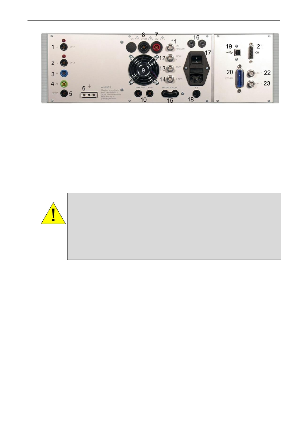
6 Reference Earth connection
7 HV output for Surge pulse
8 Common output for Surge pulse
9 Ventilation
10 Warning lamp
11 External trigger
12 BNC connector MON U
13 BNC connector MON I
6 Reference earth connection
The generator has to be connected to the reference earth plane of the test set up. The connection at the rear
part of the generator is an alternative to the grounding point at the front panel
7 HV output
The coax plug is the HV HIGH output of the simulator. It is used for external coupling/decoupling networks.
8 COM output
The Com output is the HV LOW output of the simulator. The output is floating
Attention
The direct output of the surge generator is located at the rear panel of the instrument, HV and
COM. It is not allowed to connect these outputs to any other coupling/decoupling network than
manufactured by EM TEST, e.g. the types CNV and CNI. Before to connect any external
networks to this output the operator must contact the manufacturer. Any damages due to this
matter are not covered by warranty.
The direct pulse output shall also not be used to connect the generator directly to any power
conducting lines
The wave shape measured at the direct pulse output must not be within the tolerances specified in
IEC 61000-4-5. The pulse shape shall be verified at the CDN output directly, no matter whether it
is an internal or external CDN.
9 Ventilation
After long term duration tests the generator should keep on running for some minutes to cool down the system.
10 Warning lamp
A voltage free contact is available for external warning indications (warning lamp). The signal is generated after
pressing TEST ON.
11 External trigger
One single event, burst, surge, voltage dip or ESD can be released. Trigger level 5V positive going.
12 BNC connector MON U
At this BNC connector the output power supply voltage for the EUT can be measured. Ratio 100:1 5%.
Impedance measuring instrument: 1M.
13 BNC connector MON I
At this BNC connector the output current for the EUT can be measured, e.g. the nominal current or the peak
inrush current. The rating is 10mV/A 5%. Maximum current = 1000A
Impedance measuring instrument: 1M.

EM TEST UCS 500 Series
Operating Manual V 5.40 14 / 99
14 Control output 0-10V
15 Security circuit
16 Mains selector 115V / 230V
17 Power on switch
18 Fuse of the high voltage power supply
19 Serial interface USB
20 Parallel interface IEEE
21 Remote control connector
22 FAIL 1
23 FAIL 2
14 Control output 0-10V
The voltage is used to control external power sources. The source is normally connected to the channel PF2
(normally a motor driven variac transformer). The voltage level is selectable via the operating facilities of the
UCS 500N. The voltage level can also be selected within the service menu under the function „setup.
This output is not mounted on UCS500N5E and UCS500N5V.
15 Safety circuit
The test can only be started if the security circuit is closed. If the circuit is opened during a running test the
simulator will be switched off immediately.
14 Mains selector
Selection of 115V / 230V
17 Power on switch
The switch is part of the mains filter. Mains fuses are part of the filter. (230V / 2 A and 115V / 4 A)
18 Fuse of the high voltage power supply
The high voltage power supply is protected by this fuse „F3“. In case that no high voltage is generated but the
control unit works properly this fuse shall be checked.
19 USB interface
USB interface “USB B” connector. For data-transfer a USB interface is available. The internal RS 232 interface
is converted to USB standard. Therefore the user must set the same baud-rate in the device and control
software.
Using the USB interface may cause EMC problems during burst tests at the computer or notebook side of
the communication line. Therefore a high quality USB cable (USB 2.0 standard) shall be used.
20 Parallel interface GPIB / IEEE 488
IEEE 488 interface with IEEE connector
21 Remote control connector CN
External coupling devices are controlled via this remote control connector.
22 Fail detection FAIL 1 EUT control (TEST STOP
Grounding this input will cause a complete stop of the running test procedure. (+15V to ground) The test must
be completely restarted.
23 Fail detection FAIL 2 EUT control (TEST PAUSE
Grounding this input will cause a break for the running test procedure (+15V to ground).The test will be
continued when the input is no more connected to ground.

EM TEST UCS 500 Series
Operating Manual V 5.40 15 / 99
4.
Operation
4.1.
Description of the menus
The simulator is operated by an easy menu control system. Seven function
keys are available to select parameters and functions. All functions are
indicated on the display; max. 8 lines and 40 characters.
The selected parameter is blinking and can be changed by turning the knob (inc./dec.).
: The digit for change can be selected with the cursor ( ).
- Selected values are direct indicated on the screen.
- Status on the bottom lines shows the desired status after pressing the function key.
ESC : ESC will take you back to the previous level in the menu and set the displayed
values. The latest settings are stored automatically and will be recalled when the
menu is selected again.
EXIT : The firmware will reset to the main screen.
EM TEST
UCS 500 N5
Ultra Compact Simulator
V 5.00a02
Burst
Surge
Power Fail
SWN: 001234
The serial number and the version number SWN are
used for traceability reasons. These numbers are listed
in the test reports and calibration certificates. These
numbers also are listed within the test reports
generated by the iec.control software.
Start-up display example UCS 500N5. The models type is displayed after startup.
4.2.
Menu structure
Level 0...4
Level 0
Level 1
Level 2
Level 3
Level 4
MAIN MENU
F1 BURST IEC 61000-4-4
F2 SURGE IEC 61000-4-5/9
F3 PFS IEC 61000-4-11/8/29
F7 SERVICE
Burst IEC 61000-4-4
F1 Quick Start
F2 Standard routines
F3 User test routines
Quick Start
F1 Start
F2 Change
F3 Continue
Start
Start the test routine
Change
Select all parameters
Continue
Continue the test routine
Surge IEC 61000-4-5/9
Standard routines
Preprogrammed test routines as
per standard requirements
Standard routines
F1 : F4 IEC 61000-4-4 Level 1-4
F5 Generic Standard EN 61000-6-1
F6 Generic standard EN 61000-6-2
F7 Manual standard routine
Standard routines F1..F3
F1 Start
F2 Change
F3 Continue
Power Fail IEC 61000-4-8/11/29
User test routines
Preprogrammed test routines for
evaluation and design support
F1 Synchronous to the mains
F2 Random burst release
F3 Change V after T by U
F4 Frequency sweep I
F5 Frequency sweep II
F6 Frequency sweep III
F7 Change polarity after T
User test routines F1..F3
F1 Start
F2 Change
F3 Continue
Service
F1 Addresses
F3 Setup
F4 Change standard levels
Setup
F1 Change language
F2 LCD backlighting
F3 Interfaces
F4 ESD/keyboard beeper
F5 Running time clock
F6 Set voltage
F7 Magnetic field factors
Change language Gern or English
LCD backlighting On, Off or Auto
Interfaces Select all parameters
ESD/keyboard beeper (on, off)
Running time clock
Display of the TEST ON time
Set voltage (ext. motor variac)
Magnetic field factors
Correction factors for magnetic field
antenna and current transformer
Change standard level
Change standard level
F1 All parameters to standard level
F2 IEC 61000-4
F3 EN 61000-6-1
F4 EN 61000-6-2
Change standard levels
F1 IEC 61000-4-4 Burst
F2 IEC 61000-4-5 Surge
...

EM TEST UCS 500 Series
Operating Manual V 5.40 16 / 99
4.3.
Main Menu
MAIN MENU
F1 : Burst IEC 61000-4-4
F2 : Surge IEC 61000-4-5/9
F3 : Power Fail IEC 61000-4-11/8/29
F4 : Ringwave IEC 61000-12
F5 : TSurge
F7 : Service
F1
F2
F3
F4
F5
F6
F7
F1 Burst test
With function key F1 the user can select Burst Test as per IEC 61000-4-4. The test pulses are fast transients with
a pulse shape of 5/50ns.
Attention: The generator covers the new specifications given in the draft revision IEC 61000-4-4 edition 2. This means a new spike
frequency which is selectable between 5 kHz and 100 kHz. The burst duration is automatically matched between 15ms
and 0.75ms. The common mode coupling is new with all couplings at the same time.
F2 Surge test
With function key F2 the user can select Surge Test as per IEC 61000-4-5. The test pulses are high energy pulse
with a voltage shape of 1,2/50s and a short circuit current shape of 8/20s.
In addition the test procedure for Pulse Magnetic Field testing as per IEC 61000-4-9 is included in this menu.
F3 Power Fail test
With function key F3 the user can select the Power Fail Test as per IEC 61000-4-11.
The simulator will generate voltage dips and voltage variations with preselectable parameters. IEC 61000-4-11 is
valid for ac power supply systems. For dc supply system in future IEC 61000-4-29 shall be recommended.
In addition the test procedure for 50/60Hz Magnetic Field Testing as per IEC 61000-4-8 is included within the
menu.
The Power fail menu includes a Voltage Variation test as per IEC 61000-4-11 as test procedure. The simulator
will generate voltage variations in the second range.
Attention: The generator covers already the new specifications given in FDIS IEC 61000-4-11: 2004. This means the introduction of
a new 80% test level as well as a new function for the Voltage Variation test.
F4 Ringwave as per IEC 61000-4-12 (UCS500 N7)
With function key F4 the user can select the Ring Wave Test as per IEC 61000-4-12 or ANSI/IEEE. The test
pulses are single-shot with an oscillating and decaying waveshape.
F5 Telecom Surge Test
With the Option TSurge a Telecom Surge pulse 10/700s as per IEC 61000-4-5, ITU, ETS or FCC part 68 Pulse
B is available.
F7 Service
Setup and servicing routines are available.

EM TEST UCS 500 Series
Operating Manual V 5.40 17 / 99
4.4.
Service
SERVICE
F1 : Addresses
F3 : Set-up
F4 : Change standard levels
F7 : Status
F1
F2
F3
F4
F5
F6
F7
F1 Addresses
The addresses of the EM TEST (Switzerland) GmbH
and the EM TEST GmbH are shown. The addresses
of all EM TEST sales agencies are listed on the web
site of EM Test under :
www.emtest.com
F3 Set-up
The software will clearly explain the set-up procedure.
F4 Change standard levels
The stored standard test levels can be changed within this menu.
SERVICE Change standard levels
F1 : Reset all standard levels
F2 : IEC 61000-4
F3 : EN 61000-6-1
F4 : EN 61000-6-2
F1
F2
F3
F4
F5
F6
F7
The user can change the stored standard levels
F1: Set all parameters acc. to standard. The stored standard test levels can be changed within this menu.
The settings are actualized to the standards dated in summer 2004.
F2: IEC 61000-4
F1: IEC 61000-4-4 Burst
F2: IEC 61000-4-5 Surge
F3: IEC 61000-4-8 Magnetic field AC
F4: IEC 61000-4-9 Magnetic field Surge
F5: IEC 61000-4-11 Power Fail AC
F6: IEC 61000-4-29 Power Fail DC
F3: EN 61000-6-1 Generic
F1: EN 61000-6-1 Generic Burst
F2: EN 61000-6-1 Generic Surge
F3: EN 61000-6-1 Generic Power Fail
F4: EN 61000-6-2 Generic
F1: EN 61000-6-1 Generic Burst
F2: EN 61000-6-1 Generic Surge
F3: EN 61000-6-1 Generic Power Fail

EM TEST UCS 500 Series
Operating Manual V 5.40 18 / 99
F7 Status
Status information of the equipment.
UCS500N5 UCS500N7
Page 1
UCS500N5
V5.00
005000
Built in
Modules
Model
Version
SW Number
Burst
Surge
Power Fail
Ringwave
Int. 1Ph
Operating
00000035.53 hrs
Test time
00000015.53 hrs
DI-Status 0000
SCR-Status 0000
Information of
operating
Status information
Page 2
Keyboard Beep
Countdown Beep
Backlighting
off
off
5 min
RS 232
IEEE
19200
15
Setup information
Interface information
DAC adjust
+0, +0
+0, +0
+0, +0
Voltage
V 264
Vn 230
CH PF1
H-field
Af
Tf
If
DAC Adjust
Parameter
Set voltage
H-filed
parameter

EM TEST UCS 500 Series
Operating Manual V 5.40 19 / 99
4.5.
Setup
Firmware V 6.01ax (UCS 500N5) V9.04ax (N7x)
SETUP
SETUP
F1 : Change language / Sprache ändern
F1 : Change language / Sprache ändern
F2 : LCD backlighting
F2 : LCD backlighting
F3 : Interfaces
F3 : Interfaces
F4 : Beep
F4 : Beep
F5 : Timer
F5 : Timer
F6 : Set voltage
F6 : Set voltage low / high
F7 : Magnetic field correction factors
F7 : Magnetic field correction factors
F1
F2
F3
F4
F5
F6
F7 F1
F2
F3
F4
F5
F6
F7
F1 Change language
The user can chose between two languages, German and English.
F2 LCD backlighting
With the use of F2 the backlighting can be switched on or off.
Additionally the Auto Off function can be programmed to switch off the backlighting after a defined time that the
equipment has not been in operation (1 - 30minBecause of the limited lifetime of LCD displays, approx. 10,000h
this function should always be activated.
F3 Interfaces
This menu will help the user to define the status of the integrated serial and parallel interfaces, e.g. the baud rate
of the RS 232 or the address of the IEEE interface.
F4 Beep
F1 is the selector for the keyboard beeper ON/OFF mode. (Short beep at every keyboard hit)
F3 is the selector for the countdown-beeper ON/OFF mode. (Short beep before surge pulse releasing )
To indicate that a running test is finished the beeper sounds always 3 times (not changeable).
F5 Operating time
Pressing of F5 will show the different operating time and status of the test equipment.
Operating time: Total time where the UCS is powered on.
Testing Time: Total time during a running test.
DI – Status: Service information about internal digital inputs.
SCR – Status: Service information about surge switch operation
F6 Set voltage low/high Firmware V 6.01ax (UCS 500N5) V9.04ax (N7x)
This Firmware version offers two separate voltage settings for user that needs to test equipment for 115 V and
230V mains supply. Thanks to the two settings, the user can keep the Motorvariac in the 230V position
Using a MV 2616 with voltage selector switch:
- Set the voltage selector to the 230V position for low and high mains voltage supply.
- Use the Firmware with low and high settings and use the MV 2616 for any supply in the 230 V position.
The operator can specify the following parameters:
F1: Setup Main Voltage to low 115 V. Motorvariac parameter settings for lower main voltage. (115 V)
F2: Setup Main Voltage to high 230 V Motorvariac parameters for higher main voltage. (230 V)
F3: Motorvariac high (low) Selection and indicate of the active “Main Voltage” setting. The
selected setting is used in the power Fail tests for motorvariac
control
The procedure for low and high parameters voltage setting is the same as described in F6 Set Voltage below.
F6 Set voltage
For control of an external power supply source an analogue control voltage can be programmed (0-10V dc).
The operator can specify the following parameters:
F1: Max. variac voltage V [ V ] Maximal output voltage at 100% position of the external motor variac or dc
controlled voltage source. The analogue reference value for the max. voltage is 10 V.
F2: Mains supply voltage V [ V ] of the device under test. This voltage shall be specified by the operator and
depends on the type of equipment under test. The variac normally is automatically set to this output voltage.
F3: Default channel. The operator select the default channel PF1 or PF2 from which the EUT is powered.

EM TEST UCS 500 Series
Operating Manual V 5.40 20 / 99
F7 Magnetic field correction factors
F1: Coil factor Af A/m Range [0.200...9.99 step 0.01 ]
F2: Transformer factor Tf A/V Range [0.020...9.999 step 0.001 ]
F3: Impedance factor If A/V Range [0.200...1.00 step 0.01 ]
These values are delivered together with the necessary options to conducted magnetic field testing.
- Coil factor depends on the type of antenna which is used for the test.
- Transformer factor depends on the type of transformer which is used for the test.
- Impedance factor depends on the type of surge generator which is used for the test. A generator with a
source impedance of 2 needs an impedance factor of approx. If = 0.5

EM TEST UCS 500 Series
Operating Manual V 5.40 21 / 99
4.6.
Setup procedure for Set voltage
The UCS 500 is able to control an external voltage source with a 0-10V analogue dc signal.
The 10V level corresponds to the max. output voltage of the connected voltage source. For the correct setting it
is necessary to know the max. output voltage of the source. For setting for ac or dc source the same procedure is
necessary.
Setup for adjust the external voltage variac to the UCS 500Nx
The voltage setting is a regulating procedure where one
winding of the motor-variac is approx. 1.9V. Additionally
the control needs some mechanical tolerance for stop
the step motor. Therefore the selected voltage is
normally in a tolerance of 3V
The motor-variac control has an internal deadband
where the voltage will not be adjusted.
The following procedure will guide the user through the Set Voltage procedure.
The setting for Umax and Un are listed in the boxes below. After each setting the user has to press the ESC
button for make the setting.
Step
Umax.
Un
CH
Remarks
A --
--
PF2
Set the UCS 500 to PF2 mode for measure the variable voltage
B
100
100
PF2
The variac moves to his max. voltage. ( 10V dc at the 0-10V output)
Read Umax. voltage from the voltmeter. ( MV2616 approx. 257V)
C
Umax
230
PF2
Enter Umax. and set Un to 230V ( 115V)
D
Umax
100
PF2
Check the 100V at the voltmeter. Tolerance 3V
E Umax
0
PF2
Check the 0V at the voltmeter. Tolerance < 2V
F
Umax
100
PF2
Check the 100V at the voltmeter. Tolerance 3V
G
Umax
230
PF2
Check the 230V at the voltmeter. Tolerance 3V
If the output voltage is not inside the tolerance or you like to make a better adjustment:
- Change the Umax voltage and restart the check procedure from step C to G.
EM TEST UCS 500 Series
Operating Manual V 5.40 22 / 99
5.
Test Equipment UCS 500N
The simulator UCS 500N is separated in different main parts. The control unit is screened to all other parts.
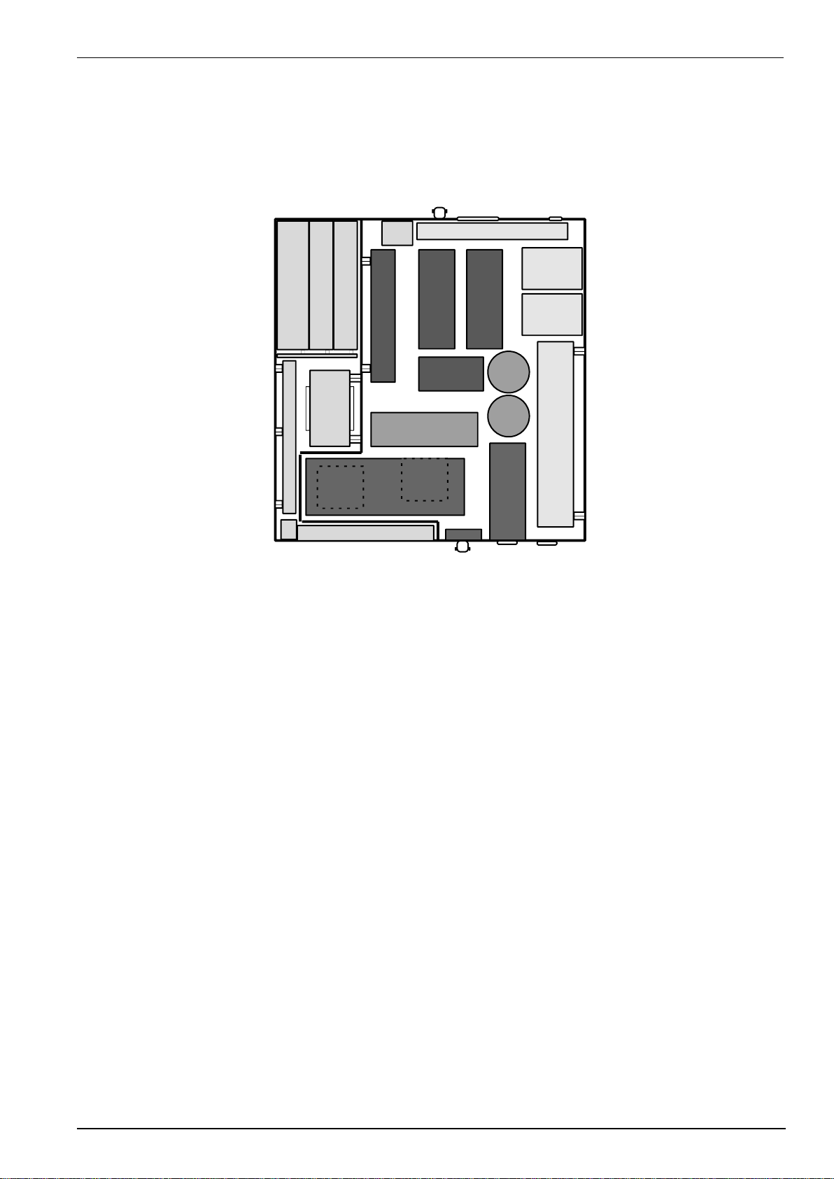
5.1.
UCS 500 N5
123
7
5
6
Front panel
Back panel
20
4
161619
19
6
18
9
10
11
13
15
17
14
14
8
21
22
23
21
12
Control unit
1 Power supply board
2 Interface board
3 Controller board
4 Power supply transformer
5 Filter board / connecting board
6 Keyboard / LCD- display
7 General power supply input, filter
8 Ventilation
High voltage unit
9 High voltage power supply
10 Storage capacitor
11 HV- board
12 ESD controller board
13 Surge switch-board
14 Coupling capacitors for surge mode
15 High voltage switch for burst mode
16 Power switches for voltage dip mode PF1, PF2
17 Current sensor
Coupling/decoupling unit
18 Filter board
19 Decoupling chokes
20 Coupling/decoupling network
21 Measuring and control output
22 Input for the power mains supply of the EUT
23 Output for the EUT supply
EM TEST UCS 500 Series
Operating Manual V 5.40 23 / 99
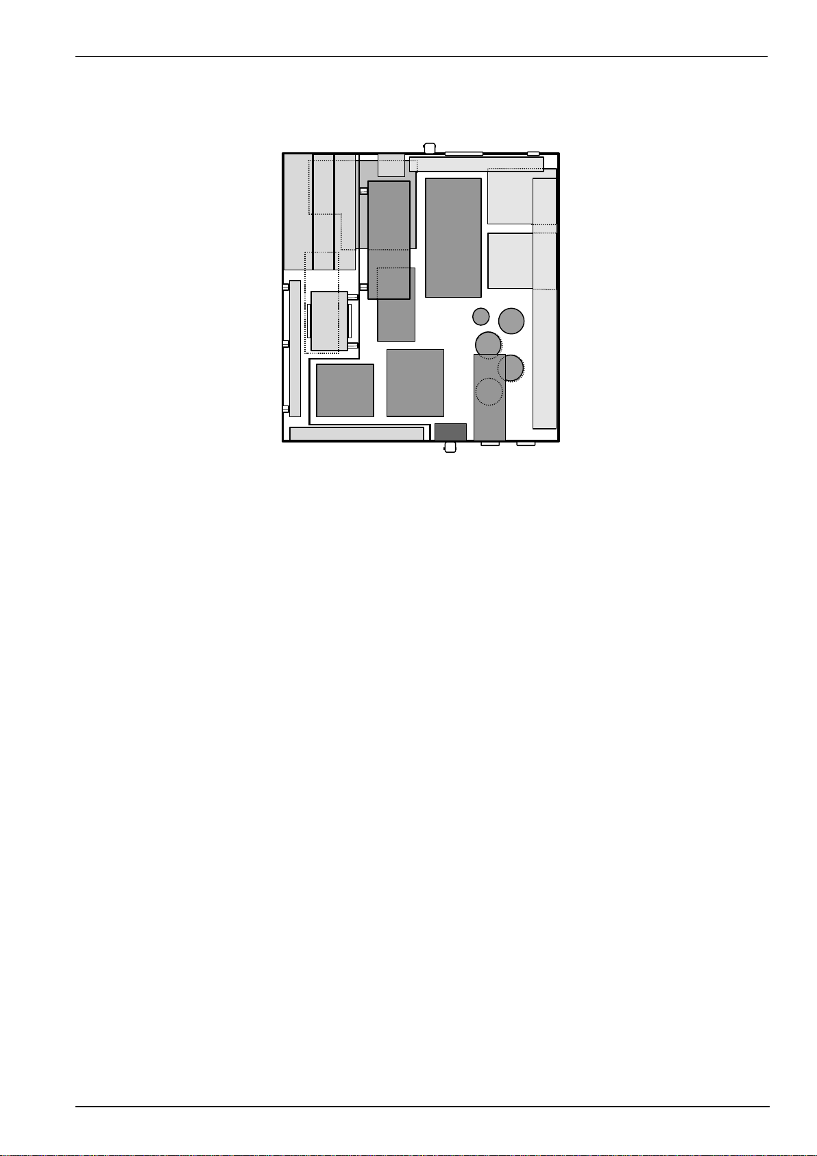
5.2.
UCS 500 N7
123
Frontpanel
Rearpanel
11
1
2
3
4
5
1
6
7
9
10
11
12
13
14
15
16
17
18
19
202021
22
23
8
7
Control unit
1 Power supply board
2 Interface board
3 Controller board
4 Power supply transformer
5 Filter board / connecting board
6 Keyboard / LCD- display
7 Measuring and control outputs
8 General power supply input, filter
9 Ventilation
High voltage unit
10 High voltage power supply
11 Surge/Burst storage capacitor
12 Ringwave storage capacitor
13 HV switching board
14 Burst module
15 Surge module
16 Ringwave module
17 Power Fail module
Coupling/decoupling unit
18 Surge/Ringwave coupling capacitors
19 Coupling network
20 Decoupling chokes
21 Filter board for the EUT supply
22 Input for the EUT supply
23 Output for the EUT supply

EM TEST UCS 500 Series
Operating Manual V 5.40 24 / 99
6.
Technical data
6.1.
EFT Electrical Fast Transients Burst as per IEC 61000-4-4
Test Level
Model N5
Model N7
Open circuit *
200V - 5500V ± 10% Step 20V
200V – 5500V ± 10% Step 50V
Wave shape into a 50 load
100V – 2750V
100V – 2750V
Rise time tr
5ns ± 30%
5ns ± 30%
Pulse duration td
50ns 30%
50ns 30%
Wave shape into a 1000 load
200V – 5500V
200V – 5500V
Rise time tr
5ns ± 30%
5ns ± 30%
Pulse duration td
35ns - 150ns
35ns – 150ns
Source impedance
Zq = 50 ± 20%
Zq = 50 ± 20%
Polarity
Positive / negative
positive / negative
Trigger
Trigger of bursts
AUTO, MANUAL, EXTERN
Synchronization
0 - 360° (16 - 500Hz)
Asynchronous = 0° a reference signal is connected to the Sync input.
Burst duration td
0.10ms – 999ms
Burst repetition rate tr
10ms – 9999ms
Spike frequency f
0.1kHz – 1000kHz Range Step
< 10 kHz 0.1 kHz
10 – 100 kHz 1.0 kHz
100 – 250 kHz 10.0 kHz
> 250 kHz 50.0 kHz
Test duration T
0:01 min - 99:59 min
Output
Direct via 50 coaxial connector
To connect ext. coupling devices
To connect ext. coupling devices
Coupling network
To L, N, PE all combinations
To L, N, PE all combinations
DUT power mains supply
AC 300 V / 16 A / 50/60 Hz
AC 300 V / 16 A / 50/60 Hz
DC 300 V / 160 A
DC 300 V / 16 A
Test routines
Quick Start
Immediate start, all parameters adjustable during a running test
Standard test as per
IEC 61000-4-4 level 1
IEC 61000-4-4 level 2
IEC 61000-4-4 level 3
IEC 61000-4-4 level 4
EN 61000-6-1 Generic
EN 61000-6-2 Generic
IEC 61000- 4-4 Manual operated standard test routine
User test routines
Synchronous burst release
Random burst release
Change level V after T by steps of dV
Frequency sweep in one single burst
Frequency sweep with constant pulses
Frequency sweep, constant burst duration
Change polarity after T
* With Burst pulses as per. IEC 61000-4-4 Ed2 : 2004 the max. output voltage can be limited.

EM TEST UCS 500 Series
Operating Manual V 5.40 25 / 99
6.2.
SURGE Immunity requirements as per IEC 61000-4-5
Test Level
Model N5
Model N7
Open circuit voltage
160 V – 5000 V ± 10% Step 20 V
250 V – 7000 V ± 10% Step 50 V
Short circuit current
80 A – 2500 A ± 10%
125 A – 3500 A ± 10%
Wave shape open circuit
coupling
18 F line to line 9 F line to ground
18 F line to line 9 F line to ground
Front time tr
1,2 s ± 30% 1,2 s ± 30%
1,2 s ± 30% 1,2 s ± 30%
Pulse duration (16A model)
50 s +10 μs/-10 μs 50 s +10 μs/-25 μs
50 s +10 μs/-10 μs 50 s +10 μs/-25 μs
Pulse duration (32A model)
50 μs +10 μs/-15 μs 50 μs +10 μs/-30 μs
50 μs +10 μs/-15 μs 50 μs +10 μs/-30 μs
Wave shape short circuit
coupling
18 F line to line 9 F line to ground
18 F line to line 9 F line to ground
Front time tr
8 s ± 20% 2.5 s ± 30%
8 s ± 20% 2.5 s ± 30%
Pulse duration
20 s ± 20% 25 s ± 30%
20 s ± 20% 25 s ± 30%
Polarity
Pos., Neg., Alt
Pos., Neg., Alt
Repetition rate
max. 1Hz (1s* - 999s)
max. 0.5Hz (2s* - 999s)
Events preselection
1 - 30'000 or endless
1 - 30'000 or endless
Counter
1 - 1000000
1 - 1000000
Trigger
Trigger of pulses
AUTO, MAN, EXTERN
AUTO, MAN, EXTERN
Synchronization
0 - 360° (16 - 500Hz)
0 - 360° (16 - 500Hz)
Synchronization
Asynchronous = 0° a reference signal is connected to the Sync input.
Resolution
1°
1°
Measurements
CRO
5 V Trigger
5 V Trigger
CRO Û
10 Vp at 5 kV
10 Vp at 7.0 kV
CRO Î
10 Vp at 2.5 kA
10 Vp at 3.5 kA ; 1 Digit 50 A
Accuracy CRO U , CRO I
± 10%
± 10%
CRO Û/I Z measuring instrument
> 1 MΩ
> 1 MΩ
Peak voltmeter
5000 V
7000 V
Peak current meter
2500 A : Display 1 Digit 20 A
3500 A : Display 1 Digit 50 A
Current limiter setting
10 A...3000 A step 10 A
10 A...4000 A step 10 A
Output N5
N7
Direct
HV-Banana connector, Zi = 2
X X
Coupling network
L – N with Z = 2
X X
L-PE, N-PE, L+N-PE with Z = 12
X X
L-PE, N-PE, L+N-PE with Z = 2
na X
DUT supply
AC 300V / 16A / 50/60 Hz
X X
DC 300V / 16A
X X
Test routines
Quick Start
Immediate start, all parameters adjustable during a running test
Standard test routines as per
IEC 61000-4-5 level 1
IEC 61000-4-5 level 2
IEC 61000-4-5 level 3
IEC 61000-4-5 level 4
EN 61000-6-1 Generic
EN 61000-6-2 Generic
IEC 61000-4-5 Manual operated standard routine
User test routines
Change polarity after n pulses
Change coupling mode after n pulses
Change voltage level V after n pulses by V
Change phase angle A after n pulses by A
Magnetic field test
test routine as per IEC 61000-4-9
test level 100, 300 and 1000A/m
cont. adjustable within Quick Start
* depends on charging voltage

EM TEST UCS 500 Series
Operating Manual V 5.40 26 / 99
6.3.
Power Fail Generator as per IEC 61000-4-11
EUT supply
Model N5
Model N7
Channel PF1 and PF2
AC voltage/current
max. 300V/16A
max. 300V/16A
Mains frequency
50/60 Hz
DC voltage/current
max. 300V/16A
max. 300V/16A
Inrush current
more than 500A
Protection
Electronic fuse for continuous overcurrent / inrush currents
Electronic control of overheating
PF1 and PF2 are safe against short circuit
max. current channel PF1
nominal current continuous
max. current channel PF2
nominal current with intermittently 10s (50% duty cycle)
Trigger
Events trigger
AUTO, MAN, EXTERN
Repetition rate
0.01s – 9’999s Accuracy 0.05% + phase sync
Duration of events
0.02ms – 9’999s Accuracy 0.05%
Events preselection
1 - 30'000 or endless
1 - 30'000 or endless
Counter
1 - 1000000
1 - 1000000
Synchronization
0 - 360° (16 - 500Hz)
Asynchronous = 0° if a reference signal is connected to the Sync input.
Max Sync input voltage
Max. 300V or same as EUT voltage specs.
Resolution
1°
Measurements
DUT supply
AC/DC voltage in the LCD display, divider ratio 1:100 +/- 10%
BNC output MON U
Measurement of the EUT supply divider ratio 1:100 5%
BNC output MON I
Measurement of the EUT current and the inrush current
10mV/A 5%, max. 1000A
CRO TRIGGER
positive going flank
0-10V Control Output
0-10V DC for external voltage source
Test routines
Quick Start
Immediate start, all parameters adjustable during a running test
Standard test routines
as per IEC 61000-4-11 ac power ports
as per IEC 61000-4-29 dc power ports
as per IEC 61000-6-1 Generic
as per IEC 61000-6-2 Generic
Manual operated standard test routine
User test routines
Voltage variation, external variac control
Change phase angle W after n events by dA
Change events duration td after n events by dtd
Inverse mode
Magnetic field test
test routine according to IEC 61000-4-8
test level 1, 3, 10 and 30A/m with MC 2630 and a variac
test level 100, 300 and 1000A/m with MC26100
Magnetic field tests per IEC 61000-4-8 and -9
The test routines for handling the magnetic field tests are included in the internal UCS 500N firmware. All functions to
control external options as voltage/current sources or magnetic field antennas are included. In addition the following
hardware is required:
Option required for Magnetic Field Test per IEC 61000-4-9
- Magnetic field antenna (square 1mx1m coil MS 100)
- Adapter for connecting the square coil to the surge output.
Option required for Magnetic Field Test 50/60Hz per IEC 61000-4-8
- External variac (MV2616) and magnetic field antenna (square 1mx1m coil MS 100)
- External current transformer (MC2630) to test 1, 3, 10 and 30 A/m levels
- External current transformer (MC26100) to test level 100, 300 and 1000 A/m levels (short term).

EM TEST UCS 500 Series
Operating Manual V 5.40 27 / 99
6.4.
RINGWAVE Immunity requirements as per IEC 61000-4-12
The Ringwave module is available for the UCS500 N7 generator.
Test level
Open circuit voltage
6000 V ± 10 %
Wave shape voltage
Rise time first peak T1
0,5 µs ± 30 %
Oscillation frequency 1/T
100kHz ± 10 %
Decaying of Pk1 to Pk2
40 % - 110 %
Decaying of Pk2 to Pk3
40 % - 80 %
Decaying of Pk3 to Pk4
40 % - 80 %
Decaying other peaks
no requirements for other peaks
Short circuit current 12 Ω
500 A ± 10 %
Short circuit current 30 Ω
200 A ± 10 %
Short circuit current 50 Ω
120 A ± 10 % option RWG / N7.1 module, no peak current measurement
Wave shape current
Rise time first peak tr T1
< 1 μs
Oscillation frequency 1/T
100 kHz ± 10 %
Decaying
no requirements
Polarity
positive / negative / alternating
Repetition rate
250 V – 4000 V max. 1 Hz (1s - 999s)
> 4000 V max. 0.1 Hz (10s – 999s)
Events preselection
1 - 30'000 or endless
Counter
1 – 1’000’000
Trigger
Trigger of pulses
AUTO, MAN, EXTERN
Synchronization
0 - 360°
Resolution
1°
Output
Direct
HV-banana connector; Zi = 12 Ω / 30 Ω / (50 Ω; option RWG/N7.1)
Coupling network
L-N, L-PE, N-PE, L+N-PE
DUT power mains supply
AC 300 V / 16 A / 50/60 Hz
DC 300 V / 16 A
Measurements
CRO
5 V Trigger
CRO Û
10 Vp at 7.0 kV
CRO Î
Output signal is not suitable for Ringwave current measurement
Peak voltmeter
0 – 7000 V
Peak current meter
Displayed value only as trend suitable, accuracy > 20%
Test routines
Quick Start
Immediate start, all parameters adjustable during a running test

EM TEST UCS 500 Series
Operating Manual V 5.40 28 / 99
6.5.
Telecom Surge Generator as per IEC 61000-4-5 (TSurge module)
UCS 500N5T (includes TSurge module) TSurge7 (external)
As per ITU and ETS recommendations
Output voltage open circuit
160V – 5’000V 10% 250V – 7’000V 10%
Pulse 10/700s
Front time TF (rise time tr)
10s 30% (1.0s 30%)
Pulse duration td
700s 20%
As per FCC part 68 Pulse B
Output voltage open circuit
160V – 5’000V 10% 250V – 7’000V 10%
Front time TF
9s 30%
Pulse duration td
720s 20%
Output current short circuit
4 – 100A 6 – 175A
Rise time tr
5s 30%
Pulse duration td
320s 20%
As per IEC 61000-4-5
Pulse 10/700s
Open circuit output voltage
160V – 5’000V 10% 250V – 7’000V 10%
Rise time tr
10s 30%
Pulse duration td
700s 20%
Short circuit output current
4 – 100A 6 – 175A
Rise time tr
5s 20%
Pulse duration td
320s 20%
Coupling
As per ITU
For 2 wire T1 and T2 with 25 each
As per FCC part 68
For 2 wire T1 and T2 with 25 each
As per IEC 61000-4-5
For 4 wire T1,T2,T3,T4 with 100 each
External networks are required for other applications (options)
General
Energy storage capacitor
20F
Polarity
Positive, negative or alternating
Counter select
1 – 30,000 or endless
Dimensions
Housing
19“, 3HU, 450x500x155mm (ext. TSurge6.1 module)
Weight
approx. 11.85kg
Accessories Included
HV cable set
Connect the TSurge module to UCS 500N7
Control cable
To control TSurge via UCS 500N7
EUT adapter
socket depends on the country of use
EM TEST UCS 500 Series
Operating Manual V 5.40 29 / 99
6.6.
EUT Supply Specifications
Standard models
Model
CDN
Remarks
UCS 500N5
300V 16A 1- ph
DC 300V / 16A
UCS 500N5.1
300V 32A 1- ph
DC 300V / 32A
UCS 500N7
300V 16A 1- ph
DC 300V / 16A ANSI
UCS 500N7.1
300V 32A 1- ph
DC 300V / 32A ANSI
DC current specification for all UCS500N model: Imax. = 16A dc (where not otherwise specified)
EUT Fuse
The UCS 500Nx models have no internal fuse for the EUT supply.
The user is responsible to adapt a suitable fuse for the EUT outside the UCS 500Nx

EM TEST UCS 500 Series
Operating Manual V 5.40 30 / 99
6.7.
General Specifications
Mains supply
230V/115V, 50/60Hz
Power consumption
110W
Fuse
230V : 2 AT slow blow
115V : 4 AT slow blow
Safety
Safety circuit
External interlock capability
Warning lamp
voltage free contact max. 250V 5A
Design
per IEC 1010, EN 61010
Interfaces
Serial
USB (compatible to USB 1.1 and 2.0)
Parallel IEEE
Address 1-31
Analog output
0-10V DC, to control an external power supply
UCS 500N5
UCS500N7
Dimensions
19" / 3 HU
19" / 6 HE
Weight
app. 25 kg
ca.. 30 kg
6.8.
Environmental conditions
Temperature
10 °C to 35 °C
Humidity
30 % to 70 %; non condensing
Atmospheric pressure
86 kPa (860 mbar) to 106 kPa (1 060 mbar)
=> Not relevant data for the standards can be changed by the manufacturer <=
EM TEST UCS 500 Series
Operating Manual V 5.40 31 / 99
6.9.
Technical data of special generators
This chapter describes differing technical data from special generators
6.9.1.
UCS 500N5.2T
Module
Built in modules
Surge, T-Surge
CDN
internal 1ph 16 A AC/DC
EUT:
Single Phase 300V 16 A
Dimensions and weight
Dimension
445 x 500 x 420 mm
Weight
Approx. 35 kg
Housing
6HU

EM TEST UCS 500 Series
Operating Manual V 5.40 32 / 99
6.9.2.
UCS 500N5.5 and UCS 500N5.6 and UCS 500N5.9 for Railways application
Standards:
- EN 50121-3-2: 2015
- EN 50121-4: 2015
- EN 50121-5: 2015
Module : Burst
Surge
EUT
UCS 500N5.5: 300V 32A
UCS 500N5.6: 300V 32A
UCS 500N5.9: 300V 16A
Module
Built in modules
UCS 500N5.5: Burst, Surge
UCS 500N5.6: Burst, Surge, Power Fail
UCS 500N5.9: Burst, Surge, Power Fail
Surge Coupling
L - N, L - PE, N - PE, L + N - PE
Surge impedance Ri
2, 10, 40 Must be set manually by a bridge
REMARK : The complete Ri impedance is the addition of the 2
generator impedance und the manually set impedance
(10, 40).
Coupling\ Ri
2
12
42 / 0.5 µF
L - N
ok
ok
ok
L - PE
N - PE
no pulse
ok
ok
L + N - PE
no pulse
ok
ok
Dimensions and weight
Dimension
450 x 550 x 285 mm
Weight
34.2kg
Housing
6HU

EM TEST UCS 500 Series
Operating Manual V 5.40 33 / 99
6.9.3.
UCS 500N5.11
Module : Burst
Surge
TSurge ( optional)
EUT: 690V 16A
Module
Available Module
Burst, Surge, TSurge
Surge coupling
L - N, L - PE, N - PE, L + N - PE
Dimensions and weight
Dimension
445 x 500 x 420 mm
Weight
37.6kg
Housing
9HU

EM TEST UCS 500 Series
Operating Manual V 5.40 34 / 99
6.9.4.
UCS 500N6.5
Module : Surge
Ring wave
CDN External CNV503B7 6kV 32A
EUT: Three Phase
3x440V 32A
Module
Built in modules
Surge, Ringwave, TSurge
Coupling
external CNV503B7 and TSurge
Dimensions and weight
Dimension
450 x 550 x 285 mm
Weight
26.0kg (UCS500N6.5) 38.0kg ( CNV503B7) 12.1kg( TSurge)
Housing
6HU
6.9.5.
UCS 500N6.7
Modules : Surge
Power Fail
Ringwave
EUT: Single Phase
Coupling Network 40A
Module
Built in modules
Surge, Power Fail, Ringwave
Surge decoupling inductance
0.6mH internal dU at 40A 50Hz 230V approx. 15V
Dimensions and weight
Dimension
663 x 550 x 600mm
Weight
94 kg
Housing
Minirack 12HU / rolls 50mm
EM TEST UCS 500 Series
Operating Manual V 5.40 35 / 99
6.9.6.
UCS 500N7.1
Modules : EFT
Surge
Power Fail
T-Surge (option)
EUT: Single Phase 300V 32A
Module
Built in modules
EFT, Surge, Power Fail
Optional module
T-Surge
Remark
Ringwave not possible
Dimensions and weight
Dimension
445 x 500 x 420mm
Weight
approx. 37.6 kg
Housing
9HU
6.9.7.
UCS 500N7.4
Modules : EFT
Surge
Power Fail
Ringwave
EUT: Single Phase 400V 16A
Module
Built in modules
EFT, Surge, Power Fail, Ringwave
Optional module
T-Surge
Remark
Ringwave not possible
Dimensions and weight
Dimension
445 x 500 x 420mm
Weight
42.8 kg
Housing
9HU
=> Not relevant data for the standards can be changed by the manufacturer <=

EM TEST UCS 500 Series
Operating Manual V 5.40 36 / 99
7.
Maintenance setup and service
7.1.
General
The generator is absolutely maintenance-free by using a solid state semiconductor switch to generate transients
7.2.
Test set- up
When setting up the test national and international regulations
regarding human safety have to be guaranteed.
It is recommended to connect the simulator to the ground reference
plane of the test set-up.
The generators of the series 500, UCS, VCS, CSS, TSS and CNI, can
be linked together to a fully automotive test set-up.
The set-up communicates via the IEEE / GPIB bus and is controlled by
software. For setting up the system see the following figures:
Each generator can be operated individual as a single equipment.
7.3.
Fuse for the EUT power supply
The EM Test pulse generators have no built in fuse for the EUT power supply. It is in the scope of responsibility
of the user to protect the EUT external for the rated current.
The design of the external fuse must be match the following rules:
- fuse dimension must be equal or smaller than the rated EUT current of the connected test
generator
- fuse must be designed for protect the connected EUT device under test in malfunction
Example of external fuse
Fuse in the building is designed for
32A. A Fuse box with 16A fuse
protection is installed between the
building supply and the test
generator.
Test generator and EUT are now
fused for 16A rated current
Example
16A protection with a 100A
installation with a 3-phase fuse box.
The user has protected his
Equipment Under Test with this
additional fuse box for a rated current
of 16A.
7.4.
Insulating- or external transformer for EUT power supply
The recommended power of an external transformer must be > 500VA. The reason is the
capacitive current of the internal filter capacitors inside the UCS 500N5 / N7.

EM TEST UCS 500 Series
Operating Manual V 5.40 37 / 99
7.5.
Calibration and verification
7.5.1.
Factory calibration
Every EM TEST generator is entirely checked and calibrated as per international standard regulations before
delivery. A calibration certificate is issued and delivered along with a list of the equipment used for the calibration
proving the traceability of the measuring equipment. All auxiliary equipment and accessories are checked to our
internal manufacturer guidelines.
The calibration certificate and the certificate of compliance (if available) show the date of calibration.
The EM Test equipment are calibrated in the factory and marked with a calibration
mark. The used measuring instruments are traceable to the Swiss Federal Office of
Metrology.
The calibration date is marked. The validity of the calibration is to the responsibility
of the user’s quality system. Neither the certificate of calibration nor the
corresponding label mark any due date for re-calibration.
Example: Calibration mark
7.5.2.
Guideline to determine the calibration period of EM Test instrumentation
Our International Service Departments and our QA Manager are frequently asked about the calibration interval of
EM TEST equipment.
EM TEST doesn’t know each customer’s Quality Assurance Policy nor do we know how often the equipment is
used and what kind of tests are performed during the life cycle of a test equipment. Only the customer knows all
the details and therefore the customer needs to specify the calibration interval for his test equipment.
In reply to all these questions we like to approach this issue as follows :
EM TEST make use of a solid state semiconductor switch technique to generate high voltage transients. A
precious advantage of this technique is the absolute lack of periodical maintenance effort. In consequence
thereof a useful calibration period has to be defined based on two criteria :
- The first one is the customer’s Quality Assurance Policy. Any existent internal regulation has to be applied at
highest priority. In the absence of such internal regulation the utilization rate of the test equipment has to be
taken into consideration.
- Based on the experience and observation collected over the years EM TEST recommend a calibration
interval of 1 year for frequently used equipment. A 2-years calibration interval is considered sufficient for
rarely used test generators in order to assure proper performance and compliance to the standard
specifications.
7.5.3.
Calibration of Accessories made by passive components only:
Passive components do not change their technical specification during storage. Consequently the measured
values and the plots stay valid throughout the storage time. The date of shipment shall be considered as the date
of calibration.
7.5.4.
Periodically In-house verification
Please refer to the corresponding standard before carrying out a calibration or verification. The standard
describes the procedure, the tolerances and the necessary auxiliary means. Suitable calibration adapters are
needed. To compare the verification results, EM Test suggests to refer to the waveshape and values of the
original calibration certificate.
All calibrations and verifications are always done without mains supply voltage connected to the coupling network
input.
Danger
Before starting the calibration or verification
remove the EUT Mains Supply
from the generator and from the coupling network

EM TEST UCS 500 Series
Operating Manual V 5.40 38 / 99
8.
Delivery Groups
8.1.
Basic equipment
Generator type UCS 500N5 with recommended modules ( Burst, Surge, Power Fail, TSurge)
UCS 500N7 with recommended modules ( Burst, Surge, Power Fail, TSurge, Ringwave)
Mains cable
Mains cable for the EUT supply
Cable black 0.5m 4mm Safety plug for phase synchronization (PF1-SYNC)
K - USB cable USB A / B , 3m
Adapter for power cable
Manual (on memory stick)
Calibration certificate
8.2.
Accessories and options
ESA Adapter for adapt different power mains connectors
As accessories adapters to different power mains connectors are part of the
delivery of EM TEST surge generators. E.g. these are adaptors for Schuko - US
- AUS - UK power mains connectors.
Most of these commercially available power mains sockets cannot withstand
surge voltages higher than 4000V. Therefore each of these EM TEST adaptors
are labeled to be used up to 4000V maximum.
In case that the EM TEST surge generator can generate higher surge voltages
than 4000V a sparkover at the power mains socket may occur.
Customers shall be aware of this matter and shall not use higher voltages than
labeled on the adapter.
For testing higher voltages it is necessary to use high voltage cables with
sufficient isolation and safety banana connectors connected direct to the
generator output plugs (L-N-PE).
Burst
CA EFT Kit Calibration Adapter for Burst verification on EUT output + KW50 +
KW1000
KW 50 Matching resistor 50 with integrated attenuator (1:100)
KW 1000 Matching resistor 1000 with integrated attenuator (1:500)
HFK Capacitive coupling clamp as per IEC 61000-4-4 to couple the fast transients
to signal and data lines.
CA HFK Calibration kit for capacitive coupling clamp as per IEC 61000-4-4 Ed.3
- Flexible plate insulated
- Support for KW 50 and adapter to KW 50
CNE 503 external 3 phase coupling/decoupling network
- EUT Mains 400 V rms max. // 480V for USA
- Rated current In = 16 A / 32A / 63A / 100 A rms
- Mains frequency 50/60 Hz
- Coupling to all phases Lx, N, PE. Control with EFT 500.
ITP Radiating set for immunity and emission
A6dB as additional 6 dB / 50 attenuator of the test signal
PUW 500 EUT monitoring

EM TEST UCS 500 Series
Operating Manual V 5.40 39 / 99
Surge
Coupling/decoupling network as per IEC 61000-4-5 for signal lines
type CNV 504/508 (4 wires and 8 wires)
3 phase CNV 503 up to 100A
TSurge module
TSurge 7
Power Fail
V4780 transformer with taps
– Transformer with taps at 40%&, 70%, 80%
- 230V / 16A
. MV 2616 Variac
– Motorvariac 0-260V / 16 or 32A
– Control signal 0-10V dc.
Magnetic field
MS 100 Magnetic field antenna
MC 2630 Current transformer up to 30A/m
MC 26100 Current transformer up to 1000A/m
MC2630 MC26100
General for Burst and Surge
CNI 503 external coupling/decoupling network
- EUT mains supply 400 V rms max. // 480V for USA
- Nominal current In = 16 A / 32A / 63A / 100 A rms
- Frequency 50/60 Hz
- Coupling to all lines, N, PE
- 50 Burst output The coupling will be controlled by the UCS 500 or EFT
500
- Output for Surge coupling to other coupling networks as CNV types ...
User software " iec.control "
- Test, analysis and documentation with windows
- License version for testing according the most automotive standards
- Report generator with export function to word-processing software
USB Interface
FER-USB
Ferrite for suppress burst pulses on the USB cable.
Application: 8 turns for the best result. max. 10cm above ground.
The included USB cable has integrated ferrites and is suitable for burst tests with
the UCS 500. Interferences usually occur on the computer side. With the ferriteFER USB Interference will be attenuated additionally on the USB cable.

EM TEST UCS 500 Series
Operating Manual V 5.40 40 / 99
9.
EFT Burst as per IEC 61000-4-4
Burst Module 5/50ns
Warning
If the user reduces the test voltage in Quick Start or in the Manual Standard Test Routine, the
storage capacitor will be discharged only by the burst pulses. The result is a higher test
voltage on the EUT than indicated on the display until the storage capacitor is discharged to the
preselected value.
If the voltage reduction is several 100V the discharge time to the correct test voltage can be
some seconds. The discharge time depends on the repetition rate tr and the duration td of the
burst pulse.
Pressing STOP / START will discharge the storage capacitor over the discharge resistor
immediately. After the START the test will continue with the correct voltage level.
9.1.
Operation
The Burst menu offers different test routines for burst testing.
Burst IEC 61000-4-4
F1 : Quick Start
F2 : Standard test routines
F3 : User test routines
F1
F2
F3
F4
F5
F6
F7
F1 Quick Start
Easy and fast online-operation with the equipment.
F2 Standard test routines
The operator can select between various preprogrammed test routines as required in different standards
F3 User test routines
The operator can select between various preprogrammed test routines which helps to accelerate testing and
which are very helpful especially during design.

EM TEST UCS 500 Series
Operating Manual V 5.40 41 / 99
9.1.1.
Quick Start
Easy and very fast operation of all standard functions of the equipment. The latest simulator settings are stored
automatically and will be recalled when Quick Start is next selected.
Burst Quick start
V = 500V f = 5kHz
td = 15ms tr = 300ms
cpl = L +/- = +
T = 01:00min
START CHANGE
F1
F2
F3
F4
F5
F6
F7
Press CHANGE and the test parameters parameter can be changed.
Select the desired parameter with the related function key and change the value by turning the front panel knob.
The cursor allows the user to define the digit to be changed (fast or slow change).
Press START and the test starts immediately with the displayed test parameters.
The operator now can navigate with the Cursor from parameter to parameter. The blinking parameter can be
changed by turning the front panel knob.
Burst specification as per IEC 61000-4-4 Ed2 : 2004
f = 5kHz
td = 15ms
tr = 300ms
f = 100kHz
td = 0.75ms
tr = 300ms

EM TEST UCS 500 Series
Operating Manual V 5.40 42 / 99
9.1.2.
Standard test routines
The user can select preprogrammed standard test routines.
Page 2
Burst Standard test routines
F1 : IEC 61000-4-4 Level 1 500V
F2 : IEC 61000-4-4 Level 2 1000V
F3 : IEC 61000-4-4 Level 3 2000V
F4 : IEC 61000-4-4 Level 4 4000V
F5 : EN 61000-6-1 Generic 1000V
F6 : EN 61000-6-2 Generic 2000V
F7 : Manual test routine
F1
F2
F3
F4
F5
F6
F7
Page 3 (Show parameters and start the test)
Burst IEC 61000-4-4 Level 3
V = 2000 V f = 100 kHz
cpl = COM
T : 00:01 min 99:59 min
f : 5.0 kHz 100 kHz
cpl : COM / ALL / CCC
T f cpl
START CHANGE
1:00 100 COM
F1
F2
F3
F4
F5
F6
F7 F1
F2
F3
F4
F5
F6
F7
The function „Change“ enables the operator to switch between 5kHz/100kHz spike frequency. The burst duration
will be automatically matched to 15ms respectively 0.75ms.
The coupling mode can be selected depending on the IEC 61000-4-4 edition version (ALL 1994 / COM 2004)
Additionally the operator can enter the required test time.
Manual standard test routine
Burst Standard routine IEC 61000-4-4
<- -> O
Level 3 2000V L N 5.0 kHz
Test time 0:00:45 h
START /- L N PE L N PE f
F1
F2
F3
F4
F5
F6
F7
Within this test routine all standard parameters can be changed online during testing at the 1-phase and coaxial
50Ω output of the UCS 500N generator. This procedure therefore is very easy and fast to use.
By pressing the function „f“ the operator can select between 5kHz and 100kHz spike frequency. The burst
duration will be automatically matched to 15ms respectively 0.75ms.
Attention: The couplings are controlled manually. The user is responsible to test according the old or new
standard IEC 61000-4-4.
Example:
- By pushing the cursor the test level will be increased/decreased to the next standard level.
- By turning the INC knob (o) the test level can be continuously adjusted.
- Pressing the function keys the related function will be immediately activated.
- The displayed time will be reset to zero after every new setting.
All functions can be operated during the running test.

EM TEST UCS 500 Series
Operating Manual V 5.40 43 / 99
9.1.3.
User Test Routines
The user can program, save and recall his own specific test routines. The next pages shows the selection of the
functions.
USER TEST ROUTINES
F1 : Synchronized
F2 : Random burst release
F3 : Voltage change after T by
F4 : Frequency sweep in one single burst
F5 : Frequency sweep with constant pulse numbers
F6 : Frequency sweep with constant burst duration
F7 : Change polarity +/- after T
F1
F2
F3
F4
F5
F6
F7
After selection the last used test parameters will be indicated on the display.
Customized test routines
The software controls user test routines according to the specification of the user. All limitations are the same as
defined under Quick Start.
Synchronized with a fixed phase angle
The burst is triggered with respect to the phase angle of the
power supply connected to the Sync input at the rear panel
of the equipment. The power supply must be an AC voltage
with a nominal frequency of 16 to 500Hz. The phase must
be connected to L. This can be checked by the lamp
connected to the L input.
Random burst release
No repetition rate is selected. The single burst will be
triggered by statistics in the limits of 20 to 2000ms as time
between two bursts. All limitations are the same as defined
under Quick Start.
Voltage change after T by V The test voltage is increased
from V1 to V2 by steps of V after the defined test time T. All
limitations are the same as defined under Quick Start. The
limitation of the max. generated number of spikes is related
to the higher voltage of V1 or V2.

EM TEST UCS 500 Series
Operating Manual V 5.40 44 / 99
Frequency sweep in one single burst
During one single burst the frequency sweeps from f1 to f2.
For this function the following limitations have to be
respected:
tr.
>=
100 ms
f1
<=
f2
td
>=
5.0 ms
td
>=
5 / f1
tr. -td
>=
50 ms
Note: The maximum value for frequency, burst duration td and voltage are in dependence of each other and therefore limited by the
generator performance. The practical limits of the UCS500N7 are 20kHz for f2 and 50ms for the burst duration td. The limits of the
generator model UCS 500N5 are approx. 10 times higher.
Frequency sweep with a constant pulse numbers
The burst duration is increased from td1 to td2 by steps of
td after the defined test time T. All limitations are the same
as defined under Quick Start. The limitation of the max.
generated number of spikes is related to the higher duration
of td1 or td2.
Frequency sweep with a constant duration after T by f
The spike frequency is increased from f1 to f2 by steps of f
after the defined test time T. All limitations are the same as
defined under Quick Start. The limitation of the max.
generated number of spikes is related to the higher
frequency of f1 or f2.
Polarity change after T
The polarity will be changed from + to - after the defined test
time T.
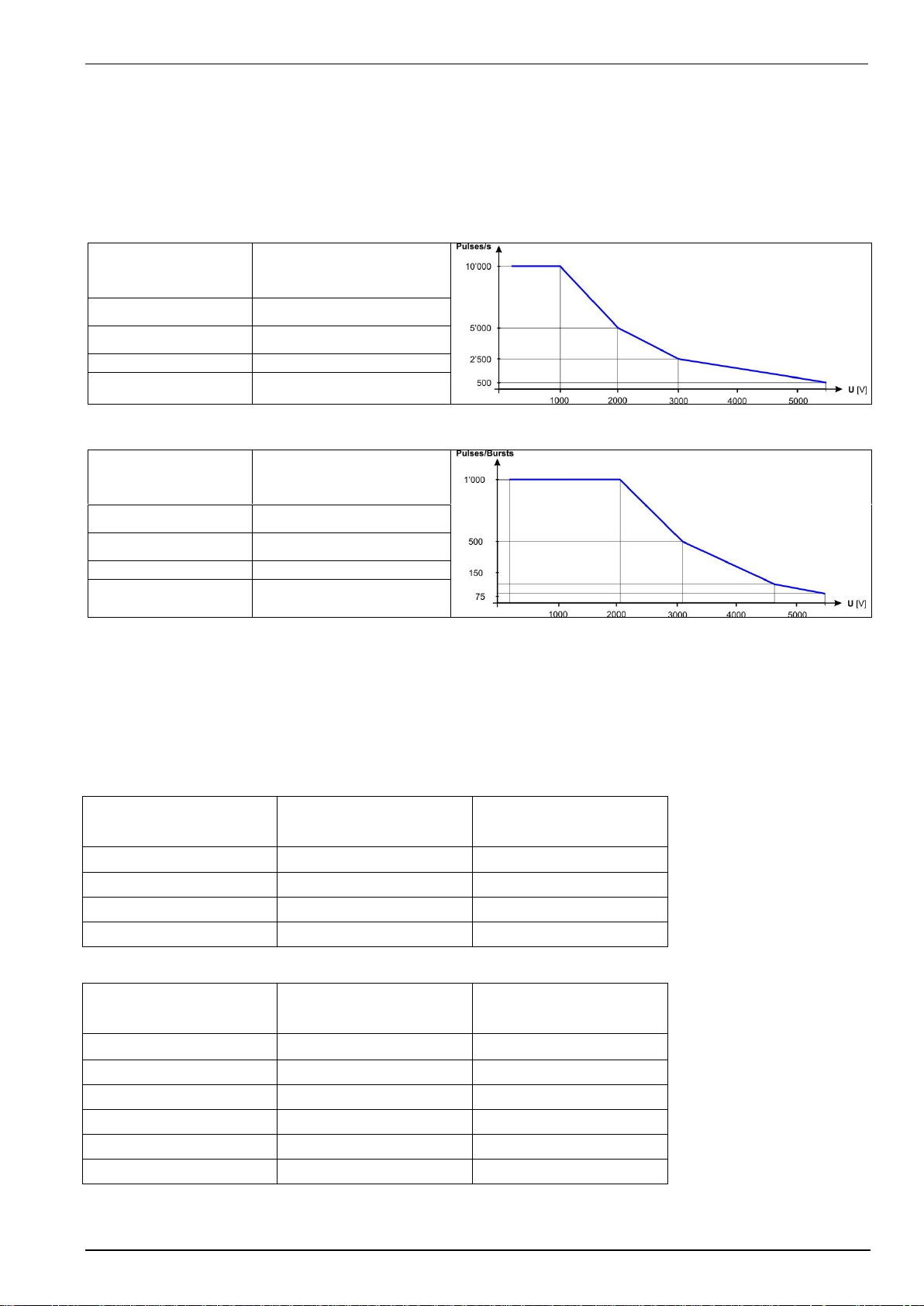
EM TEST UCS 500 Series
Operating Manual V 5.40 45 / 99
9.2.
Burst generation
Discharge switch:
The discharge switch is a highly reproducible semiconductor switch. Spike frequencies up to 1000kHz are by a
factor of 10 higher than recommended in the actual EFT standards. This means of course that also the pulse
energy would be 10 times higher. This is not generally possible for the high voltage switch. Therefore the
following limitation protects the pulse forming circuit against overload:
Pulses / s
Voltage U
max. pulses / s
td * f / tr.
<= 1'000V
10,000
> 1'000V <= 2'000V
linear decrease to 5’000
> 2'000V <= 3'000V
linear decrease to 2’500
> 3'000V <= 5'500V
linear decrease to 500
Pulses / burst
Voltage U
max. pulse / burst
td * f
<= 2'000V
1’000
> 2'000V <= 3'000V
linear decrease to 500
> 3'000V <= 4'500V
linear decrease to 150
> 4'500V <= 5'500V
linear decrease to 75
9.3.
Test level with Burst as per IEC 61000-4-4 Ed.2.
Burst generators, which the specifications in accordance with. IEC 61000-4-4 Ed2: 2004 fulfills, have a limitation
of the maximum output voltage. The efficiency of the burst pulses decreases with the numbers of couplings.
Therefore the maximum test level is limited by the number of coupling on several lines.
Generators with the modification in accordance with IEC 61000-4-4 Ed2: 2004 the. max. test levels have the
following limits:
Coupling
UCS N5
UCS N7
50
5500V
5500V
1 coupling any
5500V
5500V
2 couplings any
5500V
5000V
3 couplings any
5500V
5000V
Generator with
CNI 503 / CNE 503
50
5500V
5500V
1 coupling any
5500V
5500V
2 couplings any
5000V
5000V
3 couplings any
5000V
5000V
4 couplings any
4500V
4500V
5 couplings any
4500V
4500V
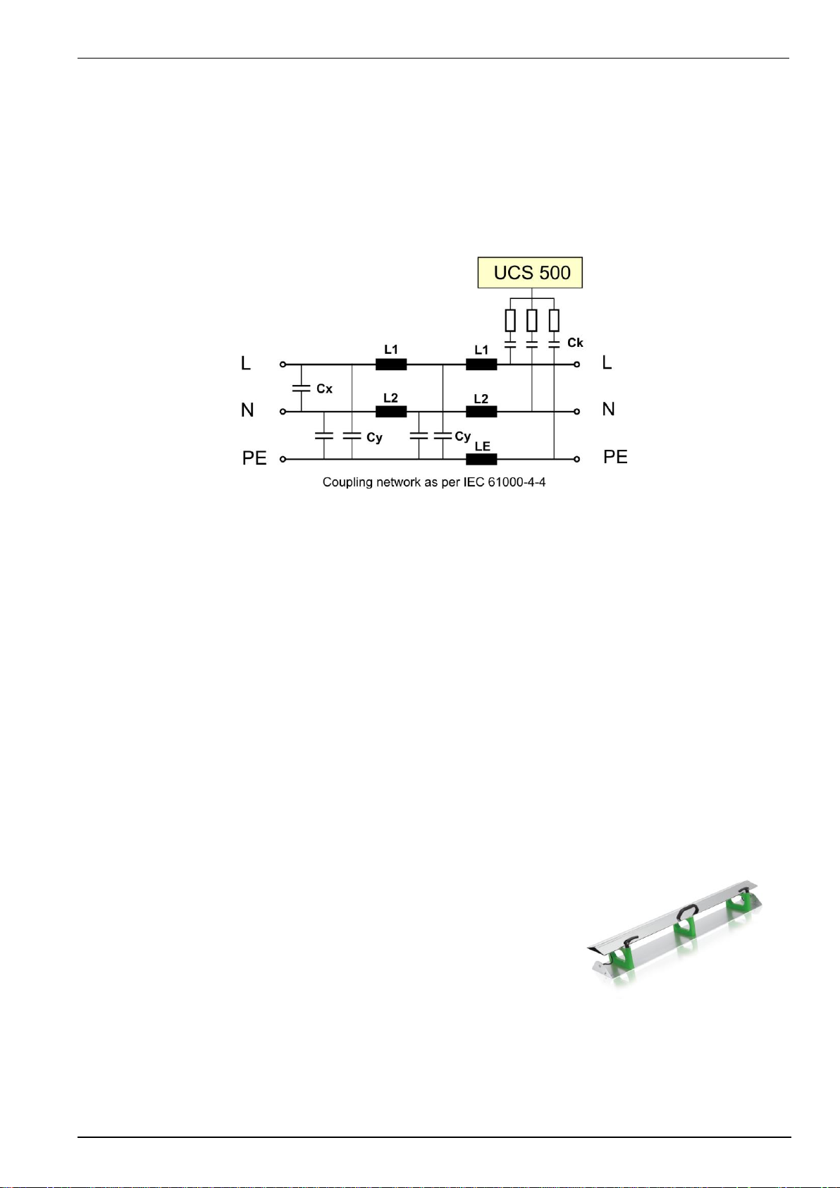
EM TEST UCS 500 Series
Operating Manual V 5.40 46 / 99
9.4.
Coupling/decoupling network
The decoupling part of the coupling network has to:
- filter the interference pulses in the direction to the power supply;
- protect other systems that are connected to the same power supply and
- realize a high impedance of the power supply, e.g. battery supply.
9.4.1.
Coupling/decoupling network for ac/dc power lines
The coupling network couples the EFT pulses via 33 nF capacitors onto the AC or DC power lines. As coupling
devices capacitors of sufficient strength and bandwidth shall be used according to IEC 61000-4-4.
The coupling on signal lines can usually not be effected capacitive without interfering with the signal flow. It is
often impossible to contact the required circuit (direct), e. g. coaxial or shielded cables. In this case the coupling
is realized with the capacitive coupling clamp. The interference simulator can be connected on both sides of the
coupling clamp.
Coupling method:
Test duration: At least 2 minutes in positive and negative polarity. The test duration must be at least as long for
examine all functions of the EUT
Coupling IEC 61000-4-4 edition 2 (2004) and later versions requires to couple all lines simultaneously in
Common Mode coupling.
This means that a EFT test needs two tests with 60s (positive and negative 60s each).
9.4.2
IEC 61000-4-4 (1995, 2001) requires all line combination to be tested individually.
A 1-phase EUT needs to test all combination L, N, PE, L+N, L+PE, N+PE, L+N+PE each with
two tests with 60s (positive and negative 60s each). Total test time 14 x 60 seconds
9.4.2.
Capacitive coupling clamp
- The coupling clamp is not matched by 50 ohm. If the clamp is matched
there exists an additional magnetic coupling, which may cause
completely different test results.
- The clamp should be placed in a distance of 0.5m to the equipment
under test. When the distance is shorter distances, the EUT may be
influenced by radiation.
- If the EUT is includes two separate equipment, the test should be
conducted on each single equipment with the required distance.
9.5.
Burst Test Setup
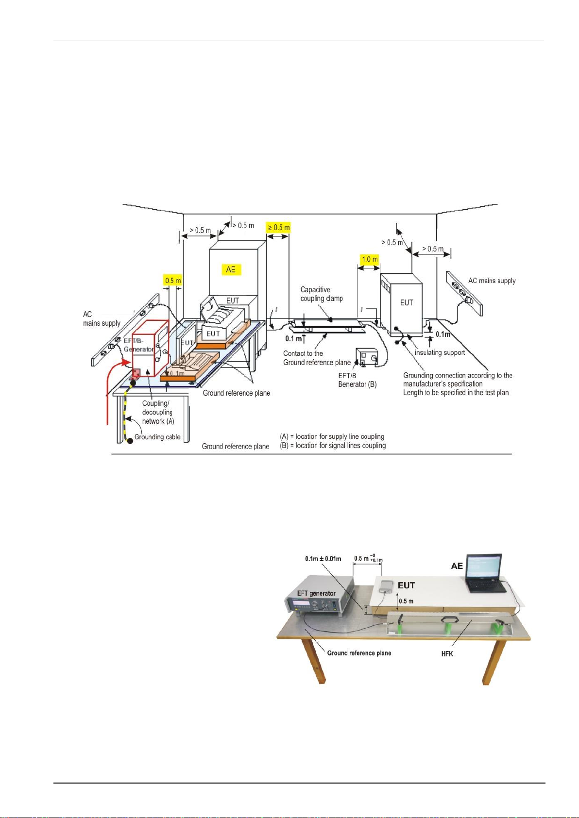
EM TEST UCS 500 Series
Operating Manual V 5.40 47 / 99
- The test generator and the coupling network should be connected to the reference ground plane (acc. to high
frequency requirements).
- The equipment under test must be isolated from the reference ground plane. The distance should be 10cm.
Being part of the EUT, these requirements are also recommended for all connected cables. The EUT should
only be grounded if this is recommended by the installation guideline. For safety reasons, the test without any
ground connection should be conducted as well (at 100MHz 1m ground cable has an impedance of about 600
ohm)
- Whenever possible the test set-up and the cabling should always be the same; e.g. for testing power lines it
would be possible to fix the cables on the test table for all tests in the same way.
- Lines under test and all other lines should be decoupled strictly.
9.5.1.
Test setup with capacitive coupling clamp
When using the coupling clamp, the minimum distance between the coupling plates and all other conductive
surfaces (including the generator), except the ground reference plane beneath the coupling clamp and beneath
the EUT, shall be at least 0,5 m.
The distance between any coupling devices
and the EUT shall be (0,5 − 0/+0,1) m for
tabletop equipment testing, and (1,0 ± 0,1) m
for floor standing equipment, unless otherwise
specified in product standards. When it is not
physically possible to apply the distances
mentioned above, other distances can be used
and shall be recorded in the test report.

EM TEST UCS 500 Series
Operating Manual V 5.40 48 / 99
10.
Surge Immunity as per IEC 61000-4-5
Surge Module 1.2/50s – 8/20s
WARNING
The internal coupling network is designed for mains frequency 50Hz / 60Hz.
When L – N coupling is selected an additional current of approx. 1.5A flows, caused by the
18F coupling capacitor and the pulse forming network. A similar current appears during the
couplings to PE.
Tests with 400 Hz mains frequency destroy the coupling network. An external coupling
network is recommended with inductors and capacitors matched to the 400Hz mains frequency.
10.1.
Operation
The Surge menu offers different test routines for burst testing.
Surge IEC 61000-4-5/9
F1 : Quick Start
F2 : Standard Test Routines
F3 : User Test Routines
F4 : Pulse Magnetic Field
F7 : Setup Current limiter
F1
F2
F3
F4
F5
F6
F7
F1 Quick Start
Easy and fast online-operation of the equipment.
F2 Standard test routines
The operator can select between various preprogrammed test routines. By pressing the related function key the
test will be started automatically with the specified test parameters.
F3 User test routines
The operator can select between various preprogrammed test routines which helps to accelerate testing and
which are very helpful especially during design.
F4 Pulse Magnetic Field
Within this menu the pulse magnetic field test as per IEC 61000-4-9 is supported.
F7 Set-up Current limiter
Within this menu the operator can select the maximum allowable surge current for the EUT. The limiter can be
selected for both coupling modes, common mode (line to ground) and differential mode (line to line).

EM TEST UCS 500 Series
Operating Manual V 5.40 49 / 99
10.1.1.
Quick Start
Easy and very fast operation of all standard functions of the equipment. The latest simulator settings are stored
automatically and will be recalled when Quick Start is next selected.
Surge Quickstart
V = 2000V A = 0 dgr
+/- = + cpl = L + N - PE
tr = 10s tri = Auto
n = endl
START CHANGE
F1
F2
F3
F4
F5
F6
F7
Press CHANGE and the test parameters parameter can be changed.
Select the desired parameter with the related function key and change the value by turning the front panel knob.
The cursor allows the user to define the digit to be changed (fast or slow change).
At polarity setting ALT it is necessary to double the number of impulses. Example n=2 => one impulse positive
and one impulse negative.
Pressing the ESC button will bring the user back to the previous level from where the test can be restarted with
new levels.
Press START and the test starts immediately with the displayed test parameters.
All functions keys except F2 (if MAN TRIGGER is selected) can stop the test routine. The latest setting will be
displayed.
Any pressing of a function key will indicate the functions START, CHANGE or CONTINUE. F3 will continue the
same test routine. If the user selects at first START or CHANGE the test will be stopped completely
Press ESC will bring the user back to the previous menu level.
Page 3 (Start)
Surge Quickstart
V = 2000V A = 0 dgr
+/- = + cpl = L + N - PE
Rep = 10 s tri = Auto
n = endl.
Vsoll = 2000V U = + 2000V COUNTER
STOP I = + 0000A 0000043
F1
F2
F3
F4
F5
F6
F7
While a test is running the user can select parameters with the cursors . The selected parameter then can be
changed online with the inc/dec knob.

EM TEST UCS 500 Series
Operating Manual V 5.40 50 / 99
10.1.2.
Standard test Routine
Page 2
Standard test routines
With the selection of F1 ....F6 the test is conducted
automatically with the parameters and the test sequence
as required per IEC 61000-4-5. The only parameters the
operator is able to change are the repetition rate and the
number of pulses per test level. With a faster repetition
rate as required in the standard the total testing time can
be reduced significantly.
F1 : IEC 61000-4-5 Level 1 500V
F2 : IEC 61000-4-5 Level 2 1000V
F3 : IEC 61000-4-5 Level 3 2000V
F4 : IEC 61000-4-5 Level 4 4000V
F5 : EN 61000-6-1 Generic 2000V
F6 : EN 61000-6-2 Generic 2000V
F7 : Manual test routine
F1
F2
F3
F4
F5
F6
F7
Tests with the function keys F1…F4 use the given testlevel with all couplings (common- and differential mode).
Iteration of the standard test procedure as per IEC 61000-4-5
The surges have to be applied
synchronized to the voltage phase at
the respective angle and the peak
value of the a.c. voltage wave (positive
and negative).
The surges have to be applied line to
line and line(s) and earth. When
testing line to earth the test voltage
has to be applied successively
between each of the lines and earth.
The test voltage has to be increased
by steps from the lowest test level up
to the test level specified in the product
standard or test plan.
List of settings EN 61000-6-1 ( each setting with 5 pulses )
Setting
Voltage
Coupling
Polarity
Phase angle
Setting
Voltage
Coupling
Polarity
Phase angle
1
2
3
4
500
L-N
pos
0
90
180
270
33
34
35
36
1000
L-PE
pos
0
90
180
270
5
6
7
8
neg
0
90
180
270
37
38
39
40
neg
0
90
180
270
9
10
11
12
L-PE
pos
0
90
180
270
41
42
43
44
N-PE
pos
0
90
180
270
13
14
15
16
neg
0
90
180
270
45
46
47
48
neg
0
90
180
270
17
18
19
20
N-PE
pos
0
90
180
270
49
50
51
52
2000
L-PE
pos
0
90
180
270
21
22
23
24
neg
0
90
180
270
53
53
55
56
neg
0
90
180
270
25
26
27
28
1000
L-N
pos
0
90
180
270
57
58
59
60
N-PE
pos
0
90
180
270
29
30
31
32
neg
0
90
180
270
57
58
59
60
neg
0
90
180
270

EM TEST UCS 500 Series
Operating Manual V 5.40 51 / 99
Standard Test Routines
Page 3 (show parameters)
Surge Generic EN 61000-4-5
5s AUTO
10 Pulse
+ 1000V
L-PE 90grd Counter
U=970V 000002
STOP STEP I = 010A 000034
F1
F2
F3
F4
F5
F6
F7
- The counter shows the number of triggered pulses per actual test level as well as the number of all triggered
test pulses within the running test sequence.
- Pushing the function key F2 STEP will bring you into the next iteration sequence.
Manual test routine
Surge Standard IEC 61000-4-5
<- -> O O
Level3 2000V 10s 0 grd L-N
START /- O V/A Rep L-N L-PE N-PE
F1
F2
F3
F4
F5
F6
F7
Within this test routine all standard parameters can be changed online during testing. This procedure therefore is
very easy and fast to use.
Example:
- Operating the cursor will increase/decrease the test level to the next level required in the standards
- By turning the inc knob the test voltage V resp. the phase angle A will be adjusted continuously. The blinking
circle shows which parameter can be changed. Pressing the function „O V/A“ will change between both
parameters.
- Pressing the function keys will activate immediately the related function.
All functions can be changed during the running test.

EM TEST UCS 500 Series
Operating Manual V 5.40 52 / 99
10.1.3.
User Test Routines
The user can program, save and recall his own specific test routines. The next pages shows the selection of the
functions.
User Test Routines
F1 : Change polarity after n pulses
F2 : Voltage change after n pulses by V
F3 : Change the phase angle after n pulses by a
F4 : IEC coupling after n pulses
F5 : ANSI A coupling after n pulses
USC 500N7 Firmware 9.00 and iec.control V 5.2.3.0 or later
F6 : ANSI B coupling after n pulses
USC 500N7 Firmware 9.00 and iec.control V 5.2.3.0 or later
F1
F2
F3
F4
F5
F6
F7
After selection the last used test parameters will be indicated on the display.
Customized test routines
The software controls user test routines according to the specification of the user. All limitations are the same as
defined under Quick Start.
F1 Change polarity after n pulses
After the release of the preselected number of pulses the
polarity is changed. The procedure always starts with
positive polarity and changes than to negative. The same
parameters as under Quick Start can be selected.
F2 Change test level V after n pulses by V
The test voltage V is changed from V1 to V2. After the preselected
number pulses the test level is changed by V until V2 is reached.
The same parameters as under Quick Start are selectable.
For the limitation of the max. admissible repetition rate the
higher value of V1 and V2 is valid.
F3 Change the phase angle A after n pulses by A
The phase angle related to which the surge pulse is
released is changed from A1 to A2. After the preselected
number of n pulses the actual phase angle is changed by A
until A2 is reached. The same parameters as under Quick
Start can be selected.

EM TEST UCS 500 Series
Operating Manual V 5.40 53 / 99
F4 IEC coupling after n pulses
The coupling mode will automatically be changed after the
preselected number of pulses has been released. All
possible coupling modes will be selected. . The same
parameters as under Quick Start can be selected.
F5 ANSI A coupling after n pulses
The coupling mode with 12Ω und 9µF will automatically be
changed after the preselected number of pulses has been
released. All possible coupling modes will be selected. . The
same parameters as under Quick Start can be selected.
F6 ANSI B coupling after n pulses
The coupling mode with 2Ω und 18µF will automatically be
changed after the preselected number of pulses has been
released. All possible coupling modes will be selected. . The
same parameters as under Quick Start can be selected.
Surge Generator and coupling impedances
Line to Line
Line to PE (IEC)
Line to GND (ANSI)
IEC
2Ω; 18µF
12Ω; 9µF
ANSI A
12Ω; 9µF
12Ω; 9µF
ANSI B
2Ω; 18µF
2Ω; 18µF

EM TEST UCS 500 Series
Operating Manual V 5.40 54 / 99
10.1.4.
Phase synchronization in 3-phase system
Device
Firmware versions
UCS 500N5
From V 4.41 to V 4.99 and from V 5.00 and higher
UCS 500N7
From V 7.43 to V 7.99 and from V 8.03 and higher
The built in hardware phase synchronization is between the sync input and PE.
The user must connect the synchronize line L1 with the sync plug.
The synchronization is based on a 3-phase system where neutral is connected to
PE in the supply system.
As Standard line L1 is connected to the sync plug. For coupling other lines, the
UCS500 hardware will automatically shift the phase angle in relation to the used
coupling.
The tables below shows the correction angels considering the phase in a 3-phase system with connected L1 to
the sync input. The UCS500 firmware will automatically add the correction angle to the settled value.
Synchronization: L1 to Sync input
Sync.
Source
Correction angel added by the UCS 500 firmware
Coupling
L1-PE
L1-N
L2-N
L3-N
L1-L2
L1-L3
L2-L3
Sync.-
Angel
0°
0°
120°
240°
330°
30°
90°
90°
0°
210°
300°
60°
120°
180°
180°
0°
300°
30°
150°
210°
270°
270°
0°
30°
150°
240°
300°
0°
The correct phase angle will be set automatically from the UCS 500N.

EM TEST UCS 500 Series
Operating Manual V 5.40 55 / 99
Device
Firmware versions
UCS 500N5
Up to V 4.40
UCS 500N7
Up to V 7.42 and from V 8.00 to V 8.02
The built in hardware phase synchronization is between the sync input and PE.
The user must connect the synchronize line with the sync plug.
The synchronization is based on a 3-phase system where neutral is connected to
PE.
As Standard line L1 is connected to the sync plug.
The table below shows the correction angels considering the phase in a 3-phase system.
Synchronization: L1 to Sync input
Sync.
Source
Settled phase angel value for coupling:
Coupling
L1-PE
L1-N
L1-PE
L2-N
L2-PE
L3-N
L3-PE
L1-L2
L1-L3
L2-L3
Sync.-
Angel
0°
0°
0°
0°
330°
30°
90°
90°
90°
90°
90°
60°
120°
180°
180°
180°
180°
180°
150°
210°
270°
270°
270°
270°
270°
240°
300°
0°
Example: For setting the coupling L1-L2 with a 180° phase angle set the generator phase to 150°

EM TEST UCS 500 Series
Operating Manual V 5.40 56 / 99
10.1.5.
Pulsed magnetic field as per IEC 61000-4-9
Page 2 (Select function)
Surge Magnetic field IEC 61000-4-9
F1 : Quick Start
F2 : Magnetic field as per IEC 61000-4-9
F7 : Setup magnetic field
F1
F2
F3
F4
F5
F6
F7
The operation of the pulse magnetic field test is similar as to the standard surge routines.
Page 2 (show parameter)
QUICKSTART
H = 300A/m A = 0 dgr
+/- = + cpl = “/” or “L-N”
tr = 10s tri = Auto
n = 10
START CHANGE
F1
F2
F3
F4
F5
F6
F7
Press START and the test routines begin to work.
Press CHANGE and the actual parameters can be changed.
For magnetic field testing the antenna correction factor shall be included. The operator can enter this
factor within the setup menu under the service routine.
Setup pulsed magnetic Test field
According IEC 61000-4-8 Ed 2, an
additional 18 uF capacitor included in the
IMN2 must be connected between the
Generator (HV – COM on rear side) and
the antenna.
Warning
Disconnect all power cables on the rear side at the Test supply plugs.
PF1, PF2 and N
Don’t touch the antenna during the test!

EM TEST UCS 500 Series
Operating Manual V 5.40 57 / 99
10.1.6.
Setup current limiter for surge current
The current limiter stops the test run when during a test the measured peak current of a surge pulse is higher
than the preselected current value. This safety function protect the EUT for further surge pulses can occur any
dangerous situation.
Depends of the different impedance of the surge generator, one current limiter for each impedance (2, 12) is
available.
Page 2 (show parameter)
SETUP Current limiter
F1 : I - Limiter Differential mode I_D
F2 : I - Limiter Common Mode I_C
I_D I_C
500A 54A
F1
F2
F3
F4
F5
F6
F7
I_D = Current limiter Differential mode (line to line): The generator impedance is 2
I_C = Current limiter Common mode (line to ground): The generator impedance is 12
REMARK
The current limits in Software and Manual operation are two individual settings.
Software uses the software settings for I_D and I_C
Manual operating uses the device settings for I_D and I_C
Note : Surge pulses with the coupling position “\” (potential free output at the rear side of the generator ) use the settings of
common mode. This is general used for the coupling network CNV 504 / 508 with 42 impedance. Using a coupling
network CNI 503 or CNV 503, UCS uses the limits of differential and common mode.

EM TEST UCS 500 Series
Operating Manual V 5.40 58 / 99
10.1.7.
Charging time for surge
The energy for charging the surge generator depends on the charging voltage of the internal capacitor of 11uF
therefore the following minimum charging time is requested:

EM TEST UCS 500 Series
Operating Manual V 5.40 59 / 99
10.2.
Surge pulse generation
Discharge switch:
The discharge switch is a highly reproducible semiconductor switch.
10.3.
Coupling/decoupling network
The coupling network has to couple the interference pulses to the lines of a power supply system (AC or DC).
Capacitive coupling is the specified coupling mode for surge testing.
10.3.1.
Coupling to ac/dc power supply lines
The surge generator UCS 500 has an integrated coupling network in accordance with IEC 61000-4-5. It must be
possible to test with different coupling modes:
Line
GND or (source impedance is 12)
Neutral
GND or (source impedance is 12)
L + N
GND or (source impedance is 12)
Line
Neutral (source impedance is 2)
Coupling Line to Line
Coupling Line to Earth
The release of the surge pulses is mostly related to a certain phase angle.
The surge pulses are synchronized to the input signal at the rear Sync-connector.
Attention: The decoupling part of the coupling/decoupling network includes some capacitors for filtering of 20F
related tp protective earth (chassis of the generator). This is to be conform with the requirement of IEC 61000-4-5
concerning attenuation of the surge transients in direction to the power mains supply input of the CDN.
As consequence there will exist an increased current to PE (protective earth) which might be hazardous to the
operator in case of a failure or wrong installation. Therefore it is very important to take the following points into
account before setting the generator into full operation.:
1. Due to this increased current into the PE system no earth fault current protectors can be used within a
surge testing area.
2. As consequence the surge generator shall be connected always to Protective Earth, even if no test is
conducted.
via plugged in power mains supply cable including the PE wire!!!!!!
via plugged in EUT power mains supply at the rear side of the generator, including the PE wire !!!!
via Ground Reference Connector, screwed to the chassis of the generator.
These measures result in double safety in case of a fault
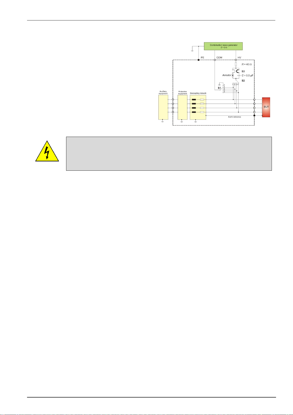
EM TEST UCS 500 Series
Operating Manual V 5.40 60 / 99
10.3.2.
Coupling to I / O lines
The coupling to I/O lines is generally realized with other
coupling networks than for power supply lines. The loading
of the I/O lines with big coupling capacitors is mostly not
possible. The data transmission may be disturbed.
For coupling to I/O lines special couplers as per IEC 610004-5 are available, such as the CNV 504N- and the
CNV 508N-series for four respectively for eight wire
systems.
For many application a special coupling network is required.
Danger
Using coupling networks CNV series
Switch OFF the high voltage during
manual change of the coupling
10.4.
Test set-up
According to the specifications of IEC 61000-4-5, the surge generator has a source impedance of 12ohm when
the simulator is coupled between the lines and protective earth.
This will activate fault current detectors or protectors which may be installed in the laboratory.
Therefore it is important
- not to disconnect the surge simulator form protective earth (power cable)
- to have an installation where the simulator is connected via its ground reference connector to earth
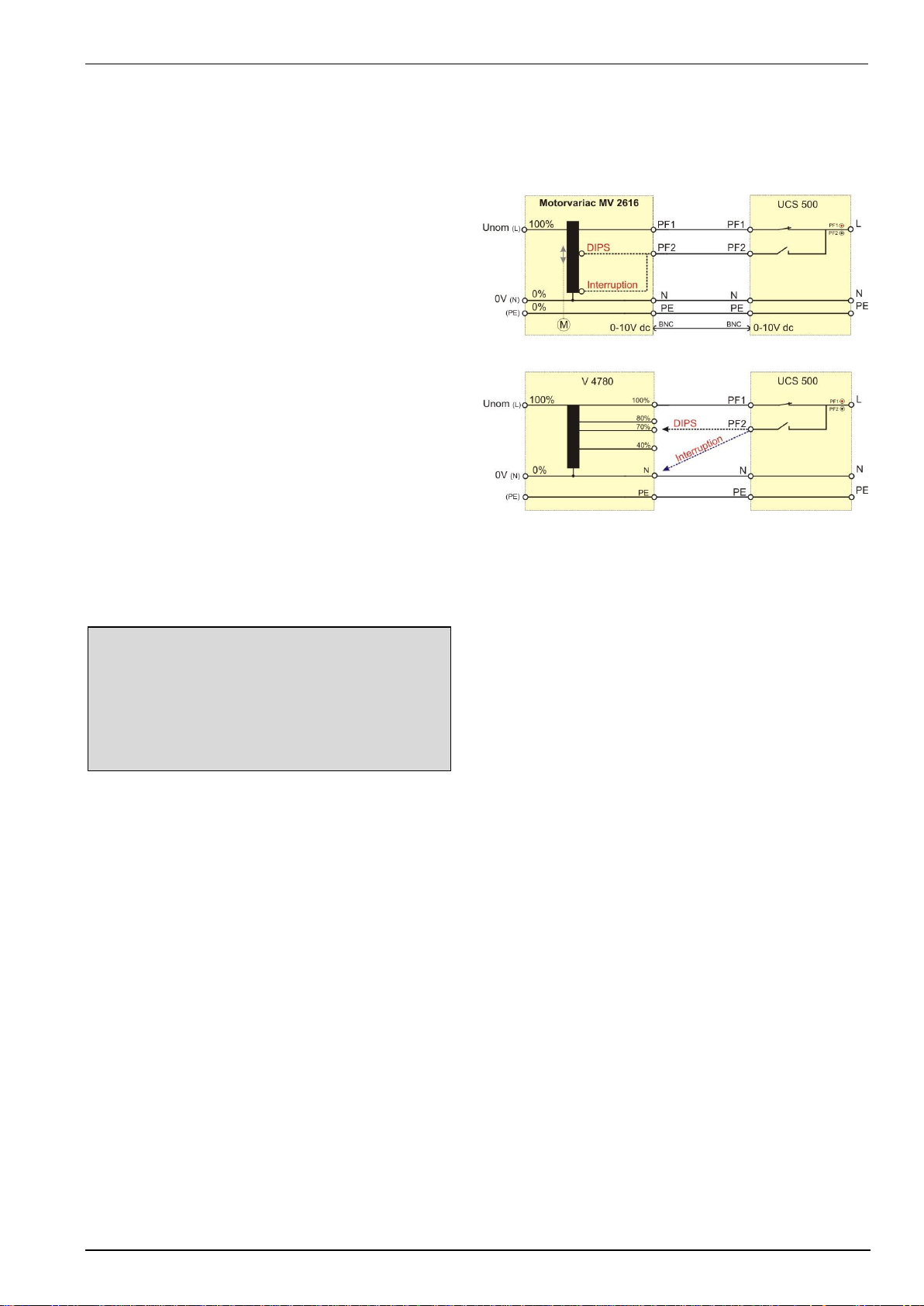
EM TEST UCS 500 Series
Operating Manual V 5.40 61 / 99
11.
Voltage Dips as per IEC 61000-4-11
Dips Module for voltage Dips and short interruptions.
11.1.
Test setup for DIPS and Interruption tests
Voltage DIPS
For voltage DIPS a connection must be made from the
PF2 UCS input to the motorvariac PF2 or V4780, where
the reduced voltage is present.
Interruption tests
For Interrupts connect the PF2 UCS input to the neutral
as follows:
- Motorvariac : PF2 output (default setting) set
motorvariac to zero volt.
- V 4780 : Connect the cable to the N output at
the V 4780
11.2.
Operation
The Surge menu offers different test routines for burst testing. The bottom line shows the selected nominal
voltage (Change in the menu F3 Setup / F6 Set voltage…)
Power Fail IEC 61000-4-11 / 8 / 29
F1 : Quick Start
F2 : Standard test routines
F3 : User test routines
F4 : Magnetic field
Motorvariac Mains Voltage 115V
Display Firmware V9.04ax and higher
F1
F2
F3
F4
F5
F6
F7
F1 Quick Start
Easy and fast online-operation of the equipment.
F2 Standard test routines
The operator can select between various preprogrammed test routines as required in different standards.
With the function key F4 the operator can select the standard routine for 50/60Hz magnetic field testing as per
IEC 61000-4-8.
F3 User test routines
The operator can select between various preprogrammed test routines which helps to accelerate testing and
which are very helpful especially during design.
F4 Magnetic Field
The operator can perform 50 / 60 Hz magnetic field test as per IEC / EN 61000-4-8.

EM TEST UCS 500 Series
Operating Manual V 5.40 62 / 99
11.2.1.
Quick Start
Easy and very fast operation of all standard functions of the equipment. The latest simulator settings are stored
automatically and will be recalled when Quick Start is next selected.
Power Fail Quickstart
A = 0dgr td = 10.00ms
rep = 0.50s CH = U
V2 = 250V tri = Auto
n = endl.
START CHANGE
F1
F2
F3
F4
F5
F6
F7
Press START and the test routines begin to work.
Press CHANGE and the actual parameters can be changed.
All function keys except F2 (manual trigger) can Stop the test routine.
Explanations
A
Phase angle
td
Duration of a single event
Rep
Repetition rate (time between two events)
CH
Channel select (PF1, PF2 or V)
V2
Variable test voltage (controlled by 0-10 V analog voltage)
n
Number of events
tri
Trigger mode
Page 3 (Start)
Power Fail Quickstart
A = 0dgr td = 10.00ms
rep = 0.50s CH = U
U2 = 250V n = endl.
tri = Auto
V = 230 V Counter
STOP I = 0.5 A 002317
F1
F2
F3
F4
F5
F6
F7
After "START" the display indicates the voltage and current at the TEST SUPPLY output. The measured voltage
is (V peak / √2 ) if there is a ac-signal on the sync input, otherwise Vpeak. The voltage dips will be repeated with
the preselected repetition rate and the counter will be increased.
When the operator is using faster repetition rates the indicated voltage level is not stable. A correct value can not
be displayed.
All function keys, except F2 Manual Trigger, can stop the running test. After Stop the last setting is displayed for
about 2 seconds. Then the functions START, CHANGE or CONT are indicated. F3 will continue the test.
During the QUICK START procedure the value for the angle is blinking. The blinking value always and at any
time can be changed by turning the knob (inc/dec). With the cursor the actual blinking function can be changed.
Page 4 (Change)
Power Fail Quickstart
A : 0dgr - 360dgr / async.
A td rep CH U2 tri n
0 10.00 050 U 250 Auto endl.
F1
F2
F3
F4
F5
F6
F7
The parameter to change can be selected by pressing a function key. The corresponding range will then be
displayed.

EM TEST UCS 500 Series
Operating Manual V 5.40 63 / 99
11.2.2.
Standard Test Routines
Standard test routines
F1 : IEC 61000-4-11 (ac power supply mains)
F2 : IEC 61000-4-29 (dc power supply systems)
F3 : EN 61000-6-1 Generic standard
F4 : EN 61000-6-2 Generic standard
F7 : Manual test routine
F1
F2
F3
F4
F5
F6
F7
11.2.2.1.
F1: IEC 61000-4-11 (AC power supply mains)
Page 3
Power Fail IEC 61000-4-11
As long as the external variac MV2616
is used, controlled by an analogue 010V control voltage, the test is
conducted automatically. If this option is
not available the manual test routine
shall be used.
F1: Level 1 0% 10.0 ms
F2: Level 2 0% 20.0 ms
F3: Level 3 40% 200 ms
F4: Level 4 70% 500 ms
F5: Level 5 80% 5000 ms
F6: Short Interruptions
F7: Voltage Variation
F1
F2
F3
F4
F5
F6
F7
Using a tapped transformer V 4780, the user must connect the PF2 UCS input with the correct plug at the V4780.
At 0% selection the PF2 input must be connected to the neutral (0V) plug.
F1 ... F5: DIPS Level 1 to Level 5
Page 4 ( Show parameter)
Power Fail IEC 61000-4-11 Level 3
V2% = 40% A = 0 dgr
td = 200ms tr = 10s
n = 3.
Counter
START / STOP 000002
F1
F2
F3
F4
F5
F6
F7
F6: Short interruptions
Page 4 ( Show parameter)
Power Fail IEC 61000-4-11 Interruption
V2% = 0 % A = 0 dgr
td = 5000ms tr = 10s
n = 3
Counter
START / STOP 000002
F1
F2
F3
F4
F5
F6
F7

EM TEST UCS 500 Series
Operating Manual V 5.40 64 / 99
F7: Voltage Variation
Page 4 ( Show parameter)
Power Fail IEC 61000-4-11 Variation
V2% = 70% A = 0 dgr
ts = 20ms tr = 10s
ti = 0.5s n = 3
Counter
START / STOP 000002
F1
F2
F3
F4
F5
F6
F7
Attention: This is the Voltage Variation function which is required in the IEC 61000-4-11:2004. The Voltage
Variation function which is conform with the previous IEC 61000-4-11 version is available in the USER
TEST ROUTINES.
Attention: This is a the voltage variation function which is required in the IEC 61000-4-11: (2004-03) and
simulate a voltage dip during a motor start. For this test requires for the ramp function a motorized
variac MV 2616 is mandatory.
The parameters, defined in the standard are fix. The user can modify the bold marked parameters :
- Phase angle W [ 0 ... 360 dgr / asynchron]
- Repetition time tr [5s ... 999s]
- Number of Events n [1 ... 30'000 / endless]
The Voltage Variation function which is conform with the older IEC 61000-4-11:1995 is available in the menu
User test routines.
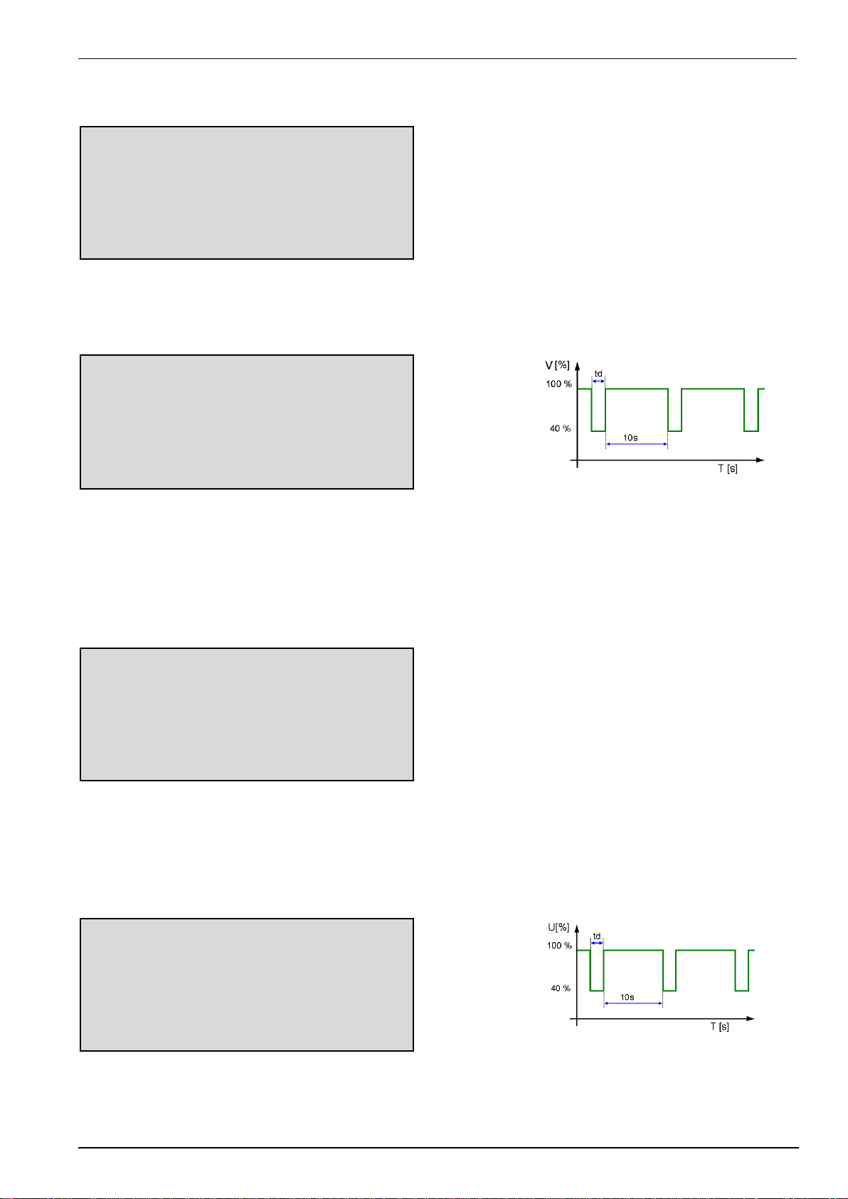
EM TEST UCS 500 Series
Operating Manual V 5.40 65 / 99
11.2.2.2.
F1: IEC 61000-4-29 ( DC power supply mains )
Page 3
Power Fail IEC 61000-4-29
F1: Level 1 40% 10.0 ms
F2: Level 2 40% 30.0 ms
F3: Level 3 40% 100 ms
F4: Level 4 40% 300 ms
F5: Level 5 40% 1000 ms
F1
F2
F3
F4
F5
F6
F7
F1 ... F5: DIPS Level 1 to Level 5
Page 4 ( Show parameter)
Power Fail IEC 61000-4-11 Level 3
V2% = 40% Ch = U
td = 100ms tr = 10s
n = 3.
Counter
START / STOP 000002
F1
F2
F3
F4
F5
F6
F7
As long as the external dc supply is used, controlled by an analogue 0-10V control voltage, the test is conducted
automatically. If this option is not available the manual test routine shall be used.
11.2.2.3.
F3 / F4: EN 61000-6-1 / -2 (Generic)
F3...F4: Generic Test Routines
Page 3
Power Fail EN 61000-6-2 Generic
V2 td A n
70% 10.0 ms 0 / 180 3
40% 100 ms 0 / 180 3
40% 1000 ms 0 / 180 3
0% 5000 ms 0 / 180 3
START CHANGE
F1
F2
F3
F4
F5
F6
F7
This test proceeds automatically with a blinking status of the actual sequence in the display. As long as the
external variac MV2616 is used, controlled by an analogue 0-10V control voltage, the test is conducted
automatically. If this option is not available the manual test routine shall be used.
Change parameters
Page 4 (Show parameter)
Power Fail EN 61000-6-2 Generic
tr : 0.01 s - 99s
tr
10
F1
F2
F3
F4
F5
F6
F7

EM TEST UCS 500 Series
Operating Manual V 5.40 66 / 99
11.2.2.4.
F7: Manual test routine
In this menu the user can easy change the parameter online during the test.
Page 4 (Show parameter)
Power Fail standard routine IEC 61000-4-11
<- -> O O
Level 4 70% 500Ns 0 grd
START oV2/td A
F1
F2
F3
F4
F5
F6
F7
Example:
- Selecting the 70% level requires a 70% Vn power supply voltage at the input of PF2 at the rear panel of the
UCS. Use for that the variac MV2616 (automatic), the matching transformer V4780 or your own power mains
source available in your laboratory.
- By pushing the function keys will immediately activate the function
– F1 : Start
– F3 : oV2/td Exchange the knob function V2Level [%] / Dip duration
– F6 : W Angle 0, 180, asynchronous
- By turning the inc knob the duration of a single event can be adjusted.

EM TEST UCS 500 Series
Operating Manual V 5.40 67 / 99
11.2.3.
User Test Routines
Page 2 (Selection)
Power Fail User test routines
F1 : Voltage variation as per IEC 61000-4-11
F2 : Change angle after n events by dA
F3 : Change duration after n events by dA
F4 : Inverse mode
F1
F2
F3
F4
F5
F6
F7
F1 Voltage variation as per IEC 61000-4-11
An external power source or motor driven variac is controlled
by a 0-10V control signal. The operator can select the time
per voltage level, the ramp up and ramp down of the voltage
change and the voltage levels itself.
Page 2 (show parameters)
Power Fail Voltage Variation
Press START and the test routines begin to work.
Press CHANGE and the actual parameter can be changed.
V1 = 220 V T1 = 10 s
V2 = 120 V T2 = 1 s
V3 = 220 V T3 = 10 s
Tf = 2.0 s Tr = 2.0 s
tri = AUTO n = 00010
START CHANGE
F1
F2
F3
F4
F5
F6
F7
F2 Change angle after n events by A
After n events the phase angle related to which the events
are released will change from A1 to A2 by steps of A until
A2 is reached. The same parameters as under Quick Start
can be selected.
F3 Change duration after n by td
After n events the duration of a single event will change from td1
to td2 by steps of td until td2 is reached.
The same parameters as under Quick Start can be selected.
F4 Inverse mode
The inverse mode can simulate a phase control circuit, switching
power (voltage) on/off at a certain phase angle. The phase angle
is selectable in the range of 0-180°. The voltage will be switched
on/off in each half-wave. Inverse is only working in U mode.
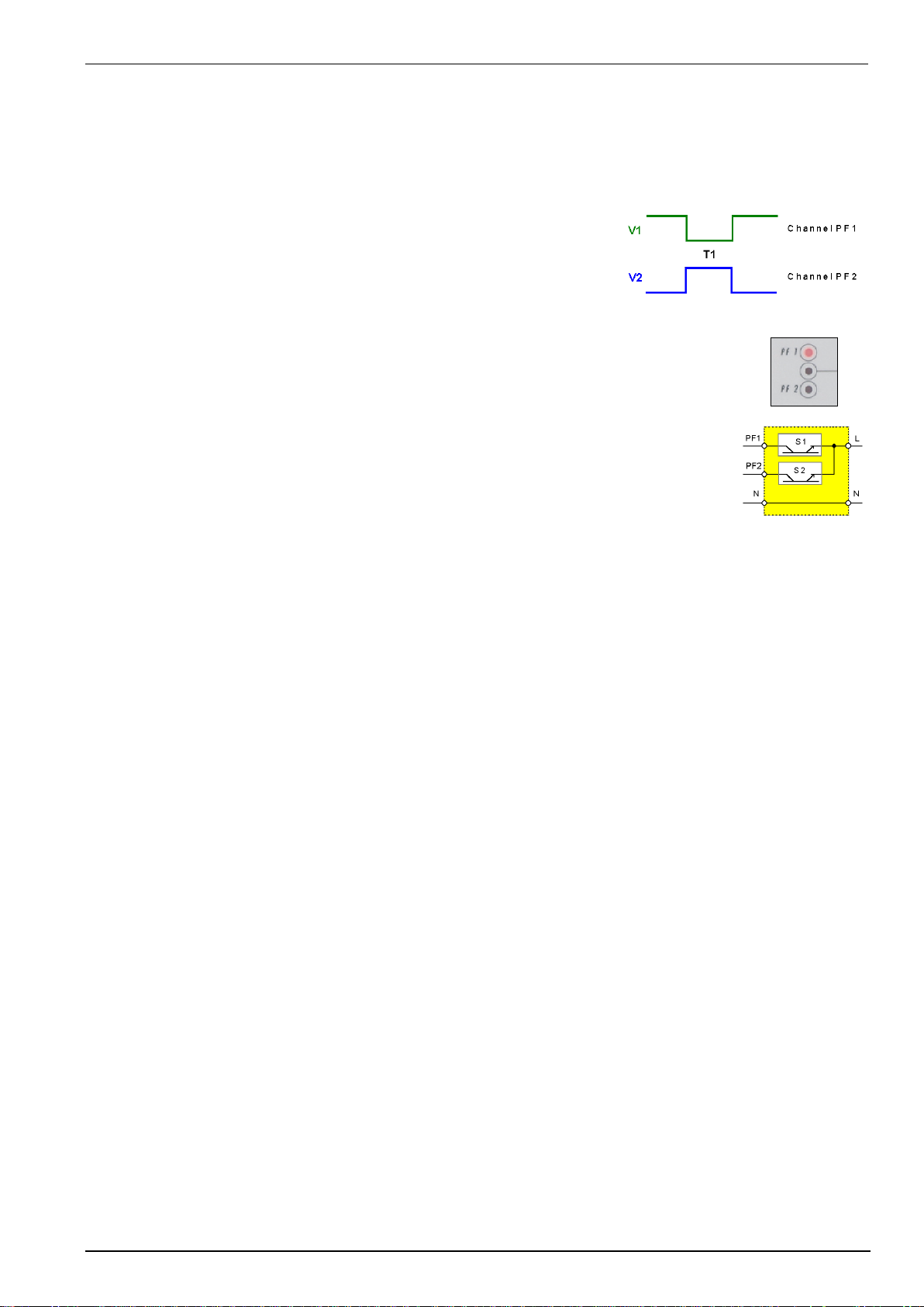
EM TEST UCS 500 Series
Operating Manual V 5.40 68 / 99
11.3.
The Power Fail Test
The power fail simulator operates in the following mode:
PF1: The voltage supply at channel PF1 will be interrupted for the preselected time T1.
PF2: The voltage supply at channel PF2 will be interrupted for the preselected time T1.
U: Channels PF1 and PF2 are supplied with different voltages; e.g.
channel PF1 with nominal voltage, channel PF2 with 15% undervoltage.
- channel PF1 is switched off for the preselected time T1.
- channel PF2 is switched on for T1.
LED
Two LED’s mounted on the front panel show if a channels is active or not. The LED of an
active channel is lighted. During mode U the LED display switches from one channel to the
other.
Voltage interference
In order to accelerate the test procedure the voltage interference may be generated
repetitively. In the operating mode „AUTO“ the events are released at a preselected interval
time.
Power switches
The power unit of the simulator consists of two electronic power switches S1 and S2. The two
separated input channels PF1 and PF2 are connected to each other at the front panel of the
simulator via S1 and S2.
Input channels
The input channels PF1 and PF2 are located at the rear part of the equipment. Attention has to be given to the
following:
1. The phase shall be connected correctly. When putting into operation check the lines with a phase
tester or with the incorporated LED phase.
2. Phase must be set on L, neutral must be set on N.
3. This applies to both channels. If during installation phase and neutral is changed, the operator will
cause a short-circuit at the input plug of the channel.
4. The neutral of both channels is connected internally and directly leads to the output.
5. The power switches can bear no more than a voltage of 350Veff.
6. If isolating transformers are used special care shall be taken to have both channels in phase.
Otherwise too high voltages, in difference mode, may occur and destroy the internal protection
devices (varistors).
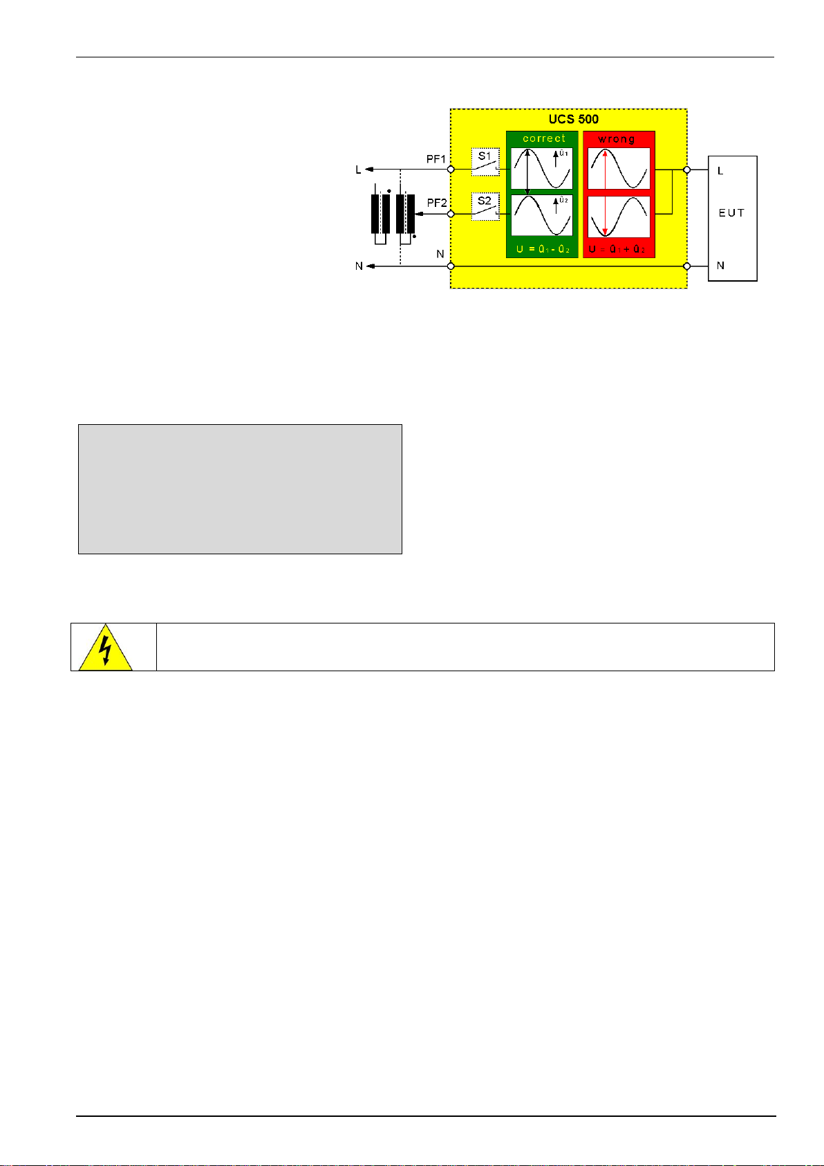
EM TEST UCS 500 Series
Operating Manual V 5.40 69 / 99
11.4.
Overcurrent
Power switches
The power switches are electronically
protected against overload and shortcircuits. The nominal current of the
switches is 25A.
Special protection requirements of the
EUT must be separately assured by the
user.
Inrush currents of = 500A are permitted.
To avoid higher inrush currents of the
EUT an electronic control limiting the
inrush current is incorporated in the
device.
Correct phase relation between PF1 and PF2
Over-voltage generated by connecting or disconnecting additional loads will be limited internally by varistors in
parallel to the electronic switch.
Power Fail Quickstart
W = 0dgr td = 10.00ms
Rep = 0.50s CH = U
U2 = 250V n = endl.
Tri = Auto
Overcurrent REMOVE SHORT CIRCUIT ! ON
Example overcurrent message in display
F1
F2
F3
F4
F5
F6
F7
Occurs an overcurrent during a test, The PF switches will switch off immediately and the display shows:
Overcurrent REMOVE SHORT CIRCUIT ! ON
This error message appears after a short circuit at the EUT output plugs. This current can be up to 700A during
few µs and will be detect from the overcurrent detection.
For overcurrent handling proceed as follow:
1. Disconnect the short circuit and make sure to remove the failure.
2. Press F7 ON. This will switch on the PF switch again and returns the power to the EUT output.
3. Continue in the start menu with CHANGE, START or CONTINUE.

EM TEST UCS 500 Series
Operating Manual V 5.40 70 / 99
11.5.
The Power Fail Test
The generator type UCS 500N5/N7 simulates the following interference :
- Voltage dips
- Voltage interruptions
- Voltage variations
- Inverse
11.5.1.
Voltage Interruptions
Depending on the preselected test parameters at the front panel of the simulator the power supply for the EUT is
interrupted for a certain time and at a certain phase angle (AC power supplies).
The power supply for the EUT is connected at the rear part of the
simulator to channel PF1.
The power supply may be taken directly from the mains power
supply or from a separate voltage source. Mostly used for this
tests are motor driven variacs
Power fail tests are normally carried out at a nominal voltage and
at maximum tolerance under-voltage.
The nominal voltage may be connected to PF1 and the reduced
dip voltage to PF2.
The power fail test may be carried out in various operating modes:
High impedance interruptions
With U mode the EUT supply is interrupted by the electronic
switch. The PF2 input is not connected. The EUT must discharge
itself internally.
Low impedance interruptions
The EUT supply is connected to PF1. The channel PF2 is shortcircuited (L-N). The EUT supply is disconnected by the electronic
switch of PF1 and the EUT will be discharged into a low
impedance via the electronic switch of PF2

EM TEST UCS 500 Series
Operating Manual V 5.40 71 / 99
11.5.2.
Voltage dips, voltage variations
Depending on the preselected test parameters, the test voltage is changed to a higher or to a lower value for a
certain duration and at a certain phase angle.
Voltage variations are normally related to the nominal value of the supply voltage. Therefore two different variacs
shall be connected at the rear side of the simulator.
- PF1 Nominal voltage
- PF2 Under- / overvoltage
The operation mode U shall be preselected. The voltage
variation is realized by switching the power supply from channel
PF1 to channel PF2.
If a motor driven variac is available, it is also possible to drive the
source by an analogue voltage 0 - 10V. This control voltage is
available at the coaxial output at the rear part of the simulator
The control voltage is to be set via the operator menu or the interfaces of the PFS. A complete user software to
drive ramps and functions is also available
11.6.
DC Power networks
Basically there is no difference in the operation of the equipment between AC and DC power supplies. The only
point the user should take care of are the grounding conditions.
The voltmeter, the "MONITOR" output and the LED are related to protective earth or to the simulator’s chassis,
respectively. Therefore these instruments can be used to check line or neutral and to measure at the output
CRO U while the test procedure is running.
It results for the DC power supply operation:
- If it is possible to ground the "MINUS" pole of the DC supply, from the EUT point of view, the blue output plug
(minus) should be connected to the green/yellow plug.
- By this way the power supply source connected at the rear side of the simulator might be grounded.
All measuring facilities are available if
- it is not possible to ground the "MINUS" pole and therefore the voltmeter cannot indicate the DC voltage.
- the phase indication led at the EUT supply input are not glowing
- there is no signal at the "CRO U" output.
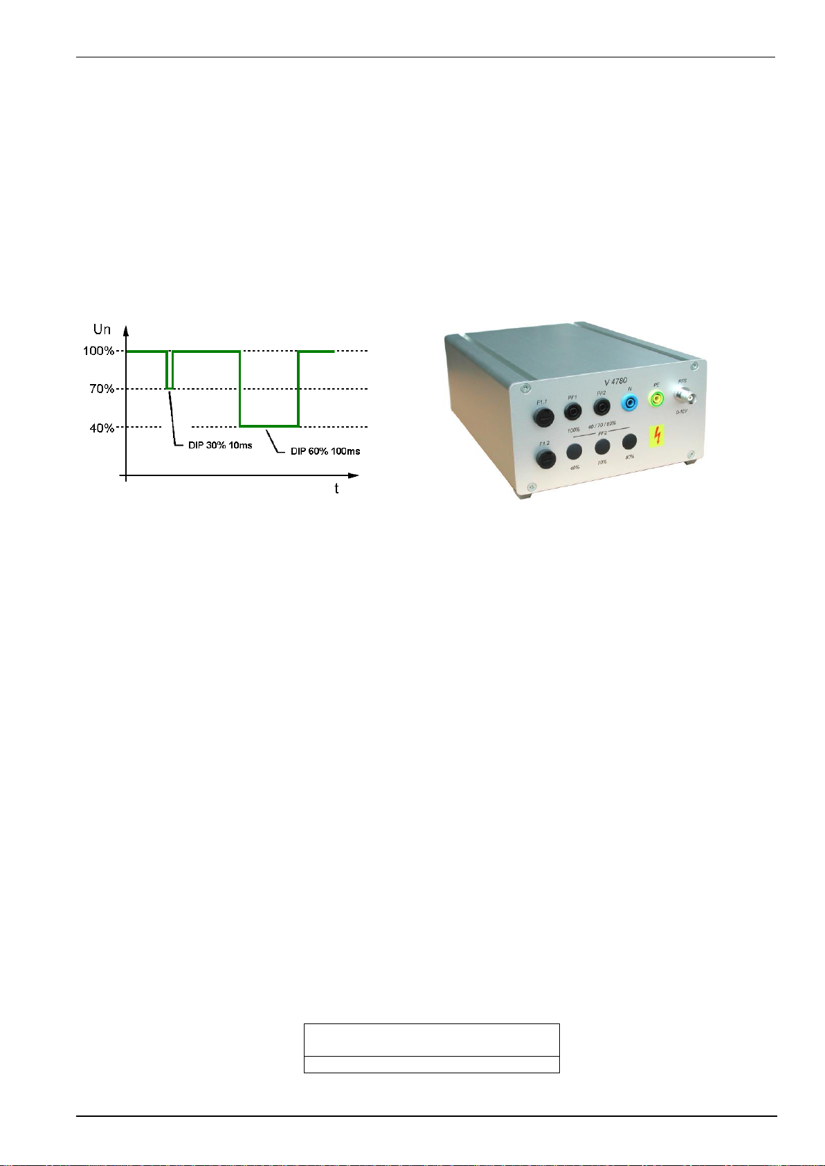
EM TEST UCS 500 Series
Operating Manual V 5.40 72 / 99
11.7.
Test setup and accessories
11.7.1.
Transformer type V4780
The transformer shall be used to generate under-voltages in ac power supply systems. According to the IEC 610004-11 and the EN 50081-2 voltage dips shall be generated as shown in fig. below. Different test levels are
recommended
11.7.1.1.
Voltage interruptions ( DIP )
Voltage interruptions will cause a reduction of the power supply voltage for a certain period of time. Three different
test levels are required:
- Voltage dip by 100% to 0% of the nominal voltage for 10ms or. ½ period
- Voltage dip by 100% to 0% of the nominal voltage for 20ms respectively 1 period
- Voltage dip by 60% to 40% of the nominal voltage for 200ms respectively 10 periods
- Voltage dip by 30% to 70% of the nominal voltage for 500Ns respectively 25 periods
- Voltage dip by 20% to 80% of the nominal voltage for 5000ms respectively 250 periods
Standard voltage dips
V 4780 S2 with automatic tap control
The transformer is an accessory to the following devices
- UCS 500Nx, PFS 500
11.7.1.2.
Device models V 4780
V4780
250V 16A, manual control
V4780 S1
250V 16A manual control additional tap at 120%
V4780 S2
250V 16A, automatic control
V4780 S3
250V 32A, manual control
11.7.1.3.
Control V4780 S2
The V4780 S2 is controlled through the analogue input (0...10Vdc). The control circuit switches to the related tap,
40%, 70% or 80%, proportional to the applied dc reference voltage (0...10V dc) to the output PF2.
Is the reference dc voltage out of the tolerance ( 0.25V), the control will not switch to any tap to the PF2 output.
Operating with ramps the control circuit will not select a tap, if the ramp (0-100%) is shorter than approx. 4s.
Programming longer ramps, each tap will switch on and off when the reference is in the valid range.
Voltage taps
DC reference voltage
80% of Unom
8.00V 0.25V
70%
7.00V 0.25V
40%
4.00V 0.25V
Settings on UCS for V4780 S2
The UCS must be matched to the 0-10V input of the V4780. Therefore a V4780 must be configured as a motor
variac. For setting V and Vn must set to the same value in menu “Setup Main Voltage to high” which is the
value of the voltage of your power supply.
Setup: F7- Service/ F3-Setup/ F6 Set voltage low/high/ F2 Setup Main Voltage to high 230V
Settings
V
Vn
CH
Example for 230V mains
230V
230V
1
Example for 100V mains
100V
100V
1
The Motorvariac must be operated in F3 Motorvariac high (control voltage DC out= 0-10V)
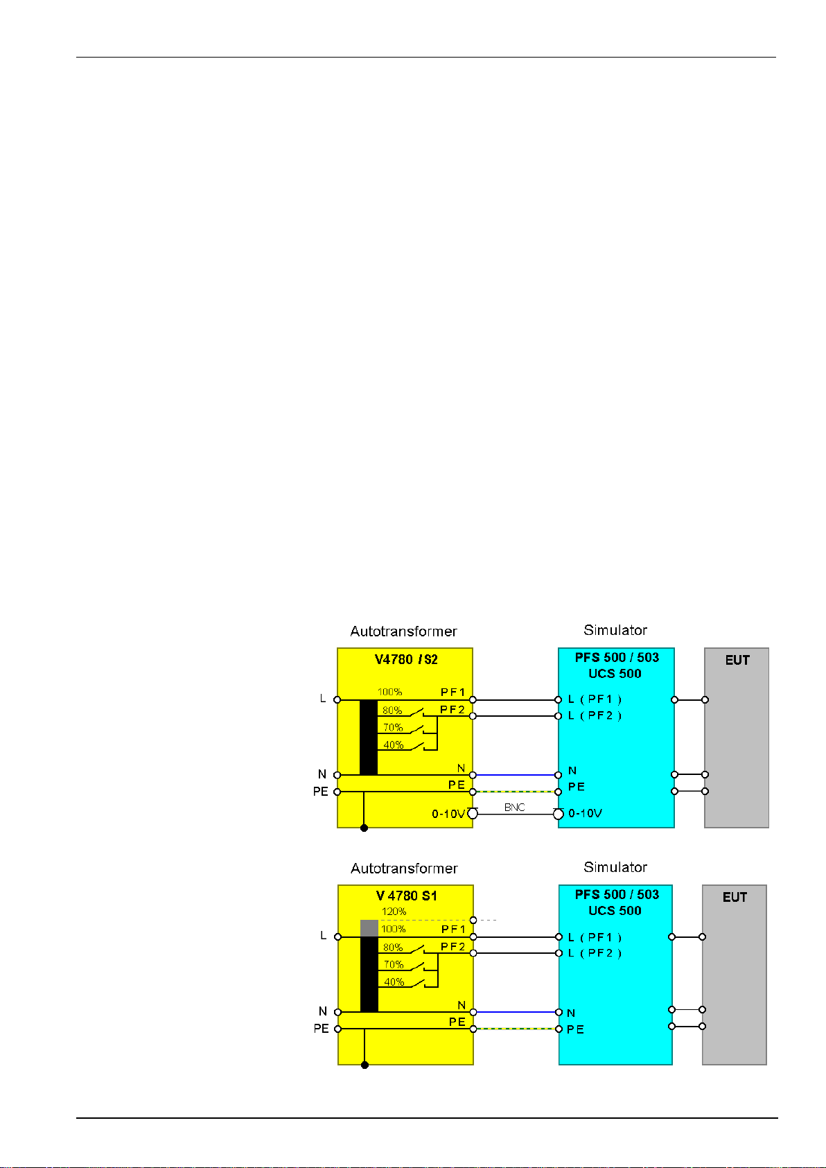
EM TEST UCS 500 Series
Operating Manual V 5.40 73 / 99
11.7.1.4.
Technical Data V4780
Design
Tapped auto-transformer with 40% , 70%, 80%, 100 % output voltage
Input:
Voltage
Uin: max. 250V
Frequency
50/60Hz
Tap selection
manually ( V4780 ) banana plugs for 40%, 70%, 80%
Remote control
0.10V dc ( V4780 S2) for 40%, 70%, 80%
Output:
Voltage tap [ % Unom ]
120% ( V4780 S1)
100%
80%
70%
40%
V4780, S1, S2
V4780 S3
Current Imax.
16A
32A
Power
4.1 kVA
8.2 kVA
Fuse
2x 16A
2x 35A
Weights and measures
Dimensions
95 x 170 x 190 mm (H x B x T)
200 x 170 x 190 mm (H x B x T)
Weights
ca. 7 kg
ca. 14 kg
Temp Ambiance
10C - 35C
10C - 35C
11.7.1.5.
Setup V4780
The output voltages are available at
safety banana plugs. For safety
reasons the related safety cables
shall be used.
The power supply input is realized
with a power connector for L, N and
PE. The voltage shall be 100% of
the nominal voltage Vn.
Connection V 4780 / V4780 S2
Connection V4780 S1

EM TEST UCS 500 Series
Operating Manual V 5.40 74 / 99
11.7.2.
Motor variac type MV 2616
The motor variac can be used to simulate power supply failures as under-voltages, voltage interruptions and voltage
variations. The basic standard IEC 61000-4-11 and the generic standard EN 50081-2 are specifying these
phenomena.
11.7.2.1.
Voltage dips / interruptions
Voltage interruptions will cause a reduction of the power supply voltage for a certain period of time. Three different
test levels are required:
- Voltage dip by 100% to 0% of the nominal voltage for 10ms or. ½ period
- Voltage dip by 100% to 0% of the nominal voltage for 20ms respectively 1 period
- Voltage dip by 60% to 40% of the nominal voltage for 200ms respectively 10 periods
- Voltage dip by 30% to 70% of the nominal voltage for 500Ns respectively 25 periods
- Voltage dip by 20% to 80% of the nominal voltage for 5000ms respectively 250 periods
Standard voltage dips
Connection diagram MV2616
The unit has to be connected at the rear part of the equipment. For connection safety laboratory cables shall be used.
11.7.2.2.
Voltage variation
Additionally it is possible to drive certain functions of variation, which also
are required in IEC 61000-4-11. These functions can easily be
programmed within the simulators itself or within the related windows
software ISMIEC
V2 Test level [ %U1]: 40%, 0%
tf Time for decreasing voltage [sec] 2 ± 20%
t1 Time at retained voltage [sec] 1 ± 20%
tr Time for increasing [sec] 2 ± 20%
For new FDIS IEC 61000-4-11 (2004) use a new procedure for voltage
variation , who simulate a voltage dip during a motor start.
The motor variac will be set previously to the voltage V2. The switch to PF2
happens in the UCS 500. Then the motor variac increase the voltage
controlled by the UCS. After ti the voltage change back to PF1
The speed of the voltage variation depends on the max. speed of the
motorvariac and the control setting of the integral action controller.
The behavior can be influenced by the parameter Vnominal. Setting in the
setup menu Setup / F5 Voltage setting.
The user can optimize his setting for the test.
Vn = Vmax of motorvariac Red curve the voltage rising is too fast.
Vn = 110% of Vnominal Green curve optimum setting
Vn = Vnominal Blue curve the voltage regulation is too slow.

EM TEST UCS 500 Series
Operating Manual V 5.40 75 / 99
11.7.2.3.
Technical data MV 2616
Input:
Voltage Vin: max. 250V
Frequency 50/60Hz
Output
Voltage Vout: 0 - 260V for channel PF2
additionally Vout=Vin for channel PF1
Current max: 16A
Power 0 - 4.1 kVA
Control
Main switch On/Off for the output voltages
Control voltage analogue 0 - 10V DC for 0-260V output voltage
Time 0..100% < 2s
Dimensions and weight
Dimensions 19" 6HE 266x485x400mm ( HxBxT )
Weight app 27 kg
Power supply 115/230V
Fuse 20A (PF1), 20A (PF2)
Environment Tmax 40C
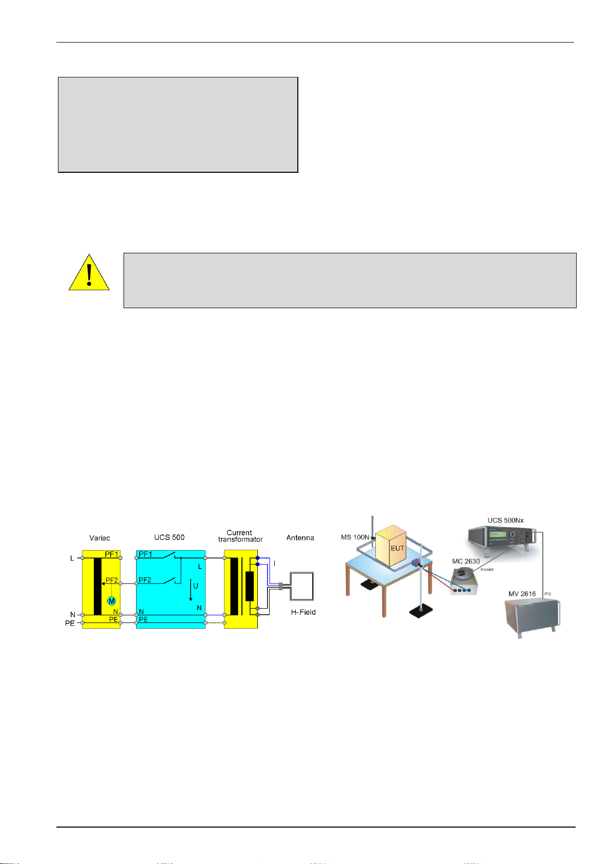
EM TEST UCS 500 Series
Operating Manual V 5.40 76 / 99
11.8.
50/60Hz Magnetic Field as per IEC 61000-4-8
Magnetic field standard routine IEC 61000-4-8
<- -> O O
5 A/m 01:00 min
START O H/T
F1
F2
F3
F4
F5
F6
F7
With the inc knob the values for the magnetic field strength and test duration can be changed. The actual
parameter is indicated by a blinking circle.
Test setup
Warning
For magnetic field testing the power mains input at PF1 shall be
disconnected.; 230V/16A.
The voltage V is adjusted with a variac as long as the required antenna current is available and the related H field
is generated in the center of the magnetic field antenna.
The variac, type MV 2616 may be controlled automatically via the test generator. Any equivalent variac available
in the lab can be used to control the current manually. Please take care that the variac has a sufficient current
capability.
For more detailed information the operator can require an additional manual especially for magnetic field
testing. This manual is part of the delivery of magnetic field testing accessories.
Test setup with MC 2630 for H-Fields up to 30A/m
Schematics Test setup
Schematics and Test setup with UCS500Nx, MV 2616, MC 2630 and MS 100N
Option for required magnetic field tests as per IEC 61000-4-8
- External motor variac MV 2616
- External Magnetic field antenna MS 100N
- External current transformer MC 2630 to test 1, 3, 10 and 30A/m levels

EM TEST UCS 500 Series
Operating Manual V 5.40 77 / 99
Test setup with MC 26100 for H-Fields up to 1000A/m
Schematics Test setup
Schematics and Test setup with UCS500Nx, MV 2616, MC 26100 and MS 100N
Option for required magnetic field tests as per IEC 61000-4-8
- External motor variac MV 2616
- External Magnetic field antenna MS 100N
- External current transformer MC 26100 to test 100 to 1000A/m levels

EM TEST UCS 500 Series
Operating Manual V 5.40 78 / 99
12.
Ringwave Immunity as per IEC 61000-4-12
Ringwave Module 0.5s – 100kHz
12.1.
Operation
The menu offers different test routines for ring wave testing.
Ring wave
F1 : Quick Start
F1
F2
F3
F4
F5
F6
F7
F1 Quick Start
Easy and fast online-operation of the equipment.
12.1.1.
Quick Start
Easy and very fast operation of all standard functions of the equipment. The latest simulator settings are stored
automatically and will be recalled when Quick Start is next selected.
Ring wave Quick start
V = 2000 V Imp = 12 Ohm
A = 0 dgr +/- = +
cpl = L+N–PE tr = 1s
tri = Auto n = endl
START CHANGE
F1
F2
F3
F4
F5
F6
F7
Press START and the test routines begin to work.
Press CHANGE and the actual parameters can be changed.
All function keys except F2 (manual trigger) can Stop the test routine.
Page 3 (START)
Ring wave Quick start
V = 2000 V Imp = 12 Ohm
A = 0 dgr +/- = +
cpl = L+N–PE tr = 1s
tri = Auto n = endl
USet = 2000V U = + 2000V Counter
STOP I = + 0A 0000043
F1
F2
F3
F4
F5
F6
F7
The user can select the parameter with the related function key and can change the value with the knob. The
cursor allows the user to define the value of the digit which should be changed (fast or slow change).
Pressing the ESC button will bring the user back to the previous level from where the test can be restarted with
new levels. After restart the actual test time is displayed. All functions keys except F2 (MAN TRIGGER) can stop
the test routine. The latest setting will be displayed.
Any pressing of a function key will indicate the functions START, CHANGE or CONTINUE. F3 will continue the
same test routine. Also the test time will continue running. If the user selects at first START or CHANGE the test
will be stopped completely.

EM TEST UCS 500 Series
Operating Manual V 5.40 79 / 99
Page 3 (CHANGE)
Ring wave Quick start
Voltage V : 250V - 6000V
angle A : 0dgr - 360dgr
Events n : 1 - 30000
Repetition Rep : 2s - 999s
V Imp A +/- cpl tr
250 12 Ohm 0 + L+N+PE 1 1/2
F1
F2
F3
F4
F5
F6
F7
Note: At polarity setting ALT it is necessary to double the number of impulses. Example n=2 => one impulse
positive and one impulse negative.
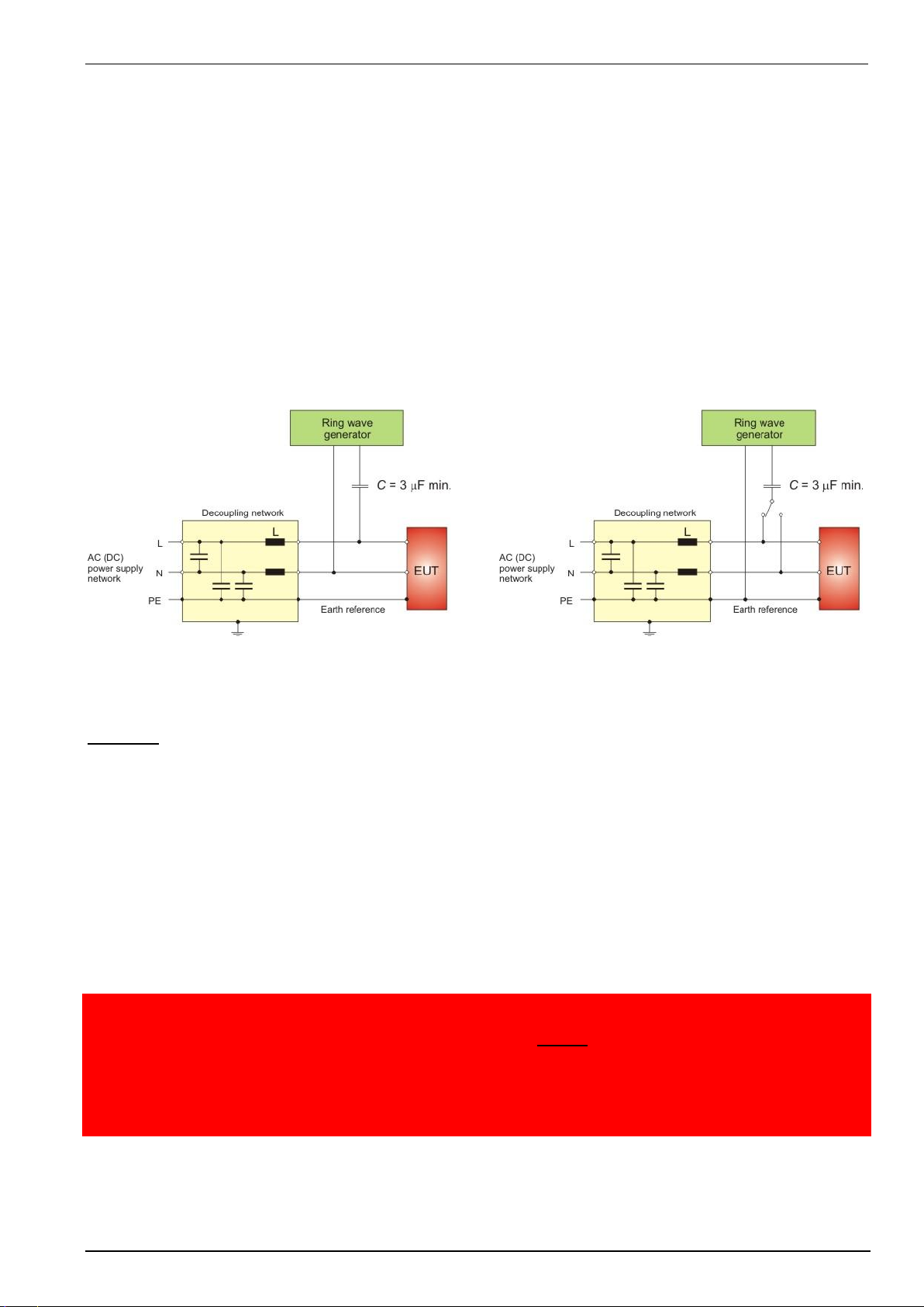
EM TEST UCS 500 Series
Operating Manual V 5.40 80 / 99
12.2.
Ring wave pulse generation
Discharge switch:
The discharge switch is a highly reproducible semiconductor switch.
12.3.
Coupling/decoupling network
The coupling network has to couple the interference pulses to the lines of a power supply system (AC or DC).
Capacitive coupling is the specified coupling mode for surge testing.
12.3.1.
Coupling to ac/dc power supply lines
The surge generator UCS 500 has an integrated coupling network in accordance with IEC 61000-4-12. It must be
possible to test with different coupling modes:
Line
GND or
Neutral
GND or
L + N
GND or
Line
Neutral
Coupling Line to Line
Coupling Line to Earth
The release of the surge pulses is mostly related to a certain phase angle.
The surge pulses are synchronized to the input signal at the rear Sync-connector.
Attention: The decoupling part of the coupling/decoupling network includes some capacitors for filtering of 20F
related tp protective earth (chassis of the generator). This is to be conform with the requirement of IEC 61000-4-5
concerning attenuation of the surge transients in direction to the power mains supply input of the CDN.
As consequence there will exist an increased current to PE (protective earth) which might be hazardous to the
operator in case of a failure or wrong installation. Therefore it is very important to take the following points into
account before setting the generator into full operation.:
12.4.
Test set-up
According to the specifications of IEC 61000-4-12, the ring wave generator has a source impedance of 12 ohm
when the simulator is coupled between the lines and protective earth.
Therefore it is important
- not to disconnect the surge simulator form protective earth (power cable)
- to have an installation where the simulator is connected via its ground reference connector to earth
1. Due to this increased current into the PE system no earth fault current protectors can be used within
a surge testing area.
2. As consequence the surge generator shall be connected always to Protective Earth, even if no test is
conducted.
via plugged in power mains supply cable including the PE wire!!!!!!
via plugged in EUT power mains supply at the rear side of the generator, including the PE wire !!!!
via Ground Reference Connector, screwed to the chassis of the generator.
These measures result in double safety in case of a fault

EM TEST UCS 500 Series
Operating Manual V 5.40 81 / 99
13.
Telecom Surge
For Telecom pulses there are the following extensions modules:
TSurge5 with built in module to the UCS500N5T that will be boosted up to 6HU.
TSurge7 as an additional module to the UCS500N7
13.1.
UCS 500N5T with Telecom Surge Module
UCS 500N5T with built in Telecom
Surge Module 10/700us
13.2.
TSurge7 Module
TSurge: Module for Telecom Surge.
10s / 700s as per. ITU and ETS
9s / 720s gem. FCC part 68 Pulse B
10s / 700s gem. IEC 61000-4-5
External TSureg7 module for UCS500N7
13.3.
TSurge7 Module
1 ON LED display TSurge active
2 Output COM plug 15
3 Output HV plug 15
4 Output T1...T4 4 x 25
1 Earth plug
2 + polarity charging
3 - polarity charging
4 COM Input TSurge – UCS
5 HV Input TSurge – UCS 500N7500N7
6 Control TSurge

EM TEST UCS 500 Series
Operating Manual V 5.40 82 / 99
13.4.
TSurge Menu
TSurge test are possible in the menu TSurge Quickstart. This menu is only available if the CTRL cable between
TSurge7 module and UCS500N7 is connected and the TSurge is detected by the UCS500N7.
The menu offers different test routines for ring wave testing.
TSURGE
F1 Quick Start
Easy and fast online-operation of the
equipment.
F1 : TSurge Quick Start
F1
F2
F3
F4
F5
F6
F7
13.4.1.
Quick Start
Easy and very fast operation of all standard functions of the equipment. The latest simulator settings are stored
automatically and will be recalled when Quick Start is next selected.
TSURGE Quick start
Press START and the test routines begin to work.
Press CHANGE and the actual parameters can be
changed.
All function keys except F2 (manual trigger) can
Stop the test routine.
V = 2000 V +/- = +
tr = 1s n = endl
tri = Auto
START CHANGE
F1
F2
F3
F4
F5
F6
F7
Page 3 (START)
TSURGE Quick start
The user can select the parameter with the
related function key and can change the value
with the knob. The cursor allows the user to
define the value of the digit which should be
changed (fast or slow change).
V = 2000 V +/- = +
tr = 1s n = endl
tri = Auto
Uset = 2000V Counter
STOP 0000043
F1
F2
F3
F4
F5
F6
F7
Pressing the ESC button will bring the user back to the previous level from where the test can be restarted with
new levels. After restart the actual test time is displayed. All functions keys except F2 (MAN TRIGGER) can stop
the test routine. The latest setting will be displayed.
Any pressing of a function key will indicate the functions START, CHANGE or CONTINUE. F3 will continue the
same test routine. Also the test time will continue running. If the user selects at first START or CHANGE the test
will be stopped completely.
Page 3 (Change)
TSURGE Quickstart
Note: At polarity setting ALT it is necessary to
double the number of impulses. Example n=2 =>
one impulse positive and one impulse negative.
Voltage V : 250V - 6000V
Events n : 1 - 30000
Repetition Rep : 2s - 999s
U Imp A +/- cpl tr
250 12 Ohm 0 + L+N+PE 1 1/2
F1
F2
F3
F4
F5
F6
F7
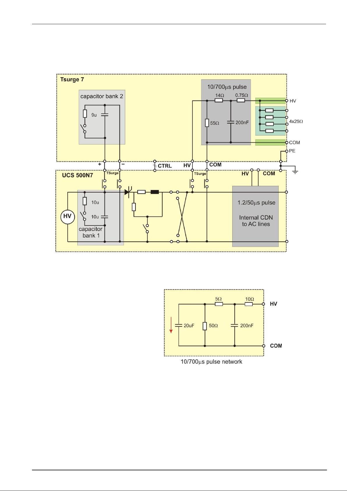
EM TEST UCS 500 Series
Operating Manual V 5.40 83 / 99
13.5.
Coupling Network
The coupling network is responsible to couple the test pulse to the lines ( ac or dc or signal lines ) using single
coupling resistors inside the TSurge module.
The Telecom surge is generated and coupled to the EUT as shown in the next figure.
The charging rectifier charges the both 10F and 9F capacitor banks in the UCS500N7 and TSurge module
Depend of the polarity the pulse forming network will be charged. The discharge switch is a highly reproducible
semiconductor switch.
Pulse 10/700s and 9/720s as per:
- ETS 300046
- ETS 300047
- CCITT K12
- FCC part 68 for Surge B

EM TEST UCS 500 Series
Operating Manual V 5.40 84 / 99
13.6.
Test Setup
Setup
The TSurge6.1 must be placed on the top of the
UCS 500N7 generator.
Cabling
1. Earth cable UCS500N7 – TSurge7
2. HV and COM cable UCS500N7 – TSurge7
3. Charging cables + / - UCS500N7 – TSurge7
4. Control cable CTRL UCS500N7 – TSurge7
Test Setup UCS500N7 and TSurge7
13.7.
Test pulses TSurge Modules
13.7.1.
Waveshape Definitions according IEC 61000-4-5 Ed 3.0
Definition of Voltage Front Time
The voltage front time is calculated by measuring the duration between 30% and 90% (tr) of the maximum pulse
amplitude and multiplying that value by 1.67
Tf = tr
30%-90%
x 1.67
Definition of Current Front Time
The current front time is calculated by measuring the duration between 10% and 90% (tr) of the maximum pulse
amplitude and multiplying that value by 1.25
Tf = tr
10%-90%
x 1.25
Definition of Decay Time
The decay time is calculated by measuring the time from the initial rise of the waveform to the point where it
decays to 50% of the maximum value. Because the time of the initial rise is difficult to measure the decay time
can be calculated by adding the time between 50% of the amplitude of rising to 50% of the amplitude of decaying
and 50% of the front time as defined before.
Td = td
50%-50%
Voltage impulse TSurge
Current impulse TSurge

EM TEST UCS 500 Series
Operating Manual V 5.40 85 / 99
13.7.2.
Pulse 10 / 700s as per IEC 61000-4-5
Voltage verification
Test level : 4000 V (for N5 type max. 5000V; respectively 7000V for N7 Type).
Pulse : 10 / 700s open circuit voltage waveshape
Output : on 25 output (internal 40 (15 + 25))
Load : open circuit
Tolerances no load
U peak
Tf
Td
pulse 10 / 700s
2000 V +/- 10%
10s +/- 30%
700s +/- 20%
Current verification
Test level : 4000 V (for N5 type max. 5000V; respectively 7000V for N7 Type).
Pulse : 5 / 320s short circuit current wave shape
Output : on 25 output (internal 40 (15 + 25))
Load : short circuit
Tolerances
I peak
Tf
Td
short circuit
100 A +/- 10%
5 s +/- 20%
320 s +/- 20%
13.7.3.
Pulse 9 / 720s as per FCC
Voltage verification
Test level : 2000 V (for N5 type max. 5000V; respectively 7000V for N7 Type)
Pulse : 9 / 720s open circuit voltage wave shape
Output : on 25 output (internal 40 (15 + 25))
Load : open circuit
Tolerances no load
U peak
Tf
Td
pulse 9 / 720s
2000 V +/- 10%
9 s +/- 30%
720s +/- 20%
Current verification
Test level : 2000 V (for N5 type max. 5000V; respectively 7000V for N7 Type).
Pulse : 5 / 330s short circuit current wave shape
Output : on 25 output (internal 40 (15 + 25))
Load : short circuit
Tolerances
I peak
Tf
Td
short circuit
50 A +/- 10%
5 s +/- 20%
330 s +/- 20%

EM TEST UCS 500 Series
Operating Manual V 5.40 86 / 99
14.
Appendix
14.1.
Declaration of CE-Conformity
14.1.1.
Declaration of Conformity UCS 500N5
Manufacturer:
EM TEST (Switzerland) GmbH
Address:
Sternenhofstr. 15
CH 4153 Reinach BL1
Switzerland
declares, that under is sole responsibility, the product’s listed below, including all their options, are conformity with the
applicable CE directives listed below using the relevant section of the following EC standards and other normative
documents.
Product‘s name:
Ultra compact generator
Model Number(s)
UCS 500N5
Low Voltage Directive 2014/35/EU
Standard to which conformity is declared:
EN 61010-1:2011
Safety requirements for electrical equipment for measurement, control, and
laboratory use.
EMC Directive 2014/30/EU
Standard(s) to which conformity is declared:
EN 61326-1:2013
Electrical equipment for measurement, control and laboratory use
(Requirements for devices to use in industrial area.)
EN 61000-3-2:2014
Limits for harmonic current emissions
EN 61000-3-3:2013
Limitation of voltage changes, voltage fluctuations and flicker in public lowvoltage supply systems.
The purpose of this instrument is the generation of defined interferences signals for EMI immunity testing.
Depending on the arrangement of the test rig, the configuration, the cabling and the properties of the EUT itself, a
significant amount of electromagnetic radiation may result that could also affect other equipment and systems.
The user himself or herself is ultimately responsible for the correct and controlled operation of the rig. In case of
doubt, the tests should be carried out in a Faraday cage.
European representative
Manufacturer
AMETEK CTS Germany GmbH
EM TEST (Switzerland) GmbH
Lünenerstr. 211
Sternenhofstr. 15
D 59174 Kamen
CH 4153 Reinach
Tel: +49 (0) 2307 / 26070-0
Tel: +41 61-7179191
Fax: +49 (0)2307 / 17050
Fax: +41 61-7179199
By
A. Gerstner
General manager
A. Burger
Design and Research
Place
Kamen, Germany
Reinach BL, Switzerland
Date
13. December 2016
25. February 2016

EM TEST UCS 500 Series
Operating Manual V 5.40 87 / 99
14.1.2.
Declaration of Conformity UCS 500N7
Manufacturer :
EM TEST (Switzerland) GmbH
Address:
Sternenhofstr. 15
CH 4153 Reinach BL1
Switzerland
declares, that under is sole responsibility, the product’s listed below, including all their options, are conformity with the
applicable CE directives listed below using the relevant section of the following EC standards and other normative
documents.
Product‘s name:
Ultra compact generator
Model Number(s)
UCS 500N7
Low Voltage Directive 2014/35/EU
Standard to which conformity is declared:
EN 61010-1:2011
Safety requirements for electrical equipment for measurement, control, and
laboratory use.
EMC Directive 2014/30/EU
Standard(s) to which conformity is declared:
EN 61326-1:2013
Electrical equipment for measurement, control and laboratory use
(Requirements for devices to use in industrial area.)
EN 61000-3-2:2014
Limits for harmonic current emissions
EN 61000-3-3:2013
Limitation of voltage changes, voltage fluctuations and flicker in public lowvoltage supply systems.
The purpose of this instrument is the generation of defined interferences signals for EMI immunity testing.
Depending on the arrangement of the test rig, the configuration, the cabling and the properties of the EUT itself, a
significant amount of electromagnetic radiation may result that could also affect other equipment and systems.
The user himself or herself is ultimately responsible for the correct and controlled operation of the rig. In case of
doubt, the tests should be carried out in a Faraday cage.
European representative
Manufacturer
AMETEK CTS Germany GmbH
EM TEST (Switzerland) GmbH
Lünenerstr. 211
Sternenhofstr. 15
D 59174 Kamen
CH 4153 Reinach
Tel: +49 (0) 2307 / 26070-0
Tel: +41 61-7179191
Fax: +49 (0)2307 / 17050
Fax: +41 61-7179199
By
A. Gerstner
General manager
A. Burger
Design and Research
Place
Kamen, Germany
Reinach BL , Switzerland
Date
13. December 2016
25. February 2016

EM TEST UCS 500 Series
Operating Manual V 5.40 88 / 99
14.1.3.
Declaration of Conformity UCS 500N5x models for one phenomenon
Manufacturer :
EM TEST (Switzerland) GmbH
Address:
Sternenhofstr. 15
CH 4153 Reinach BL1
Switzerland
declares, that under is sole responsibility, the product’s listed below, including all their options, are conformity with the
applicable CE directives listed below using the relevant section of the following EC standards and other normative
documents.
Product‘s name:
Ultra compact generator
Model Number(s)
UCS500N5V, UCS500N5E, UCS500N5P
Low Voltage Directive 2014/35/EU
Standard to which conformity is declared:
EN 61010-1:2011
Safety requirements for electrical equipment for measurement, control, and
laboratory use.
EMC Directive 2014/30/EU
Standard(s) to which conformity is declared:
EN 61326-1:2013
Electrical equipment for measurement, control and laboratory use
(Requirements for devices to use in industrial area.)
EN 61000-3-2:2014
Limits for harmonic current emissions
EN 61000-3-3:2013
Limitation of voltage changes, voltage fluctuations and flicker in public lowvoltage supply systems.
The purpose of this instrument is the generation of defined interferences signals for EMI immunity testing.
Depending on the arrangement of the test rig, the configuration, the cabling and the properties of the EUT itself, a
significant amount of electromagnetic radiation may result that could also affect other equipment and systems.
The user himself or herself is ultimately responsible for the correct and controlled operation of the rig. In case of
doubt, the tests should be carried out in a Faraday cage.
European representative
Manufacturer
AMETEK CTS Germany GmbH
EM TEST (Switzerland) GmbH
Lünenerstr. 211
Sternenhofstr. 15
D 59174 Kamen
CH 4153 Reinach
Tel: +49 (0) 2307 / 26070-0
Tel: +41 61-7179191
Fax: +49 (0)2307 / 17050
Fax: +41 61-7179199
By
A. Gerstner
General manager
A. Burger
Design and Research
Place
Kamen, Germany
Reinach BL , Switzerland
Date
13. December 2016
25. February 2016

EM TEST UCS 500 Series
Operating Manual V 5.40 89 / 99
14.1.4.
Declaration of Conformity UCS 500N5x models
Manufacturer :
EM TEST (Switzerland) GmbH
Address:
Sternenhofstr. 15
CH 4153 Reinach BL1
Switzerland
declares, that under is sole responsibility, the product’s listed below, including all their options, are conformity with the
applicable CE directives listed below using the relevant section of the following EC standards and other normative
documents.
Product‘s name:
Ultra compact generator (special models)
Model Number(s)
UCS500Nx.x
Low Voltage Directive 2014/35/EU
Standard to which conformity is declared:
EN 61010-1:2011
Safety requirements for electrical equipment for measurement, control, and
laboratory use.
EMC Directive 2014/30/EU
Standard(s) to which conformity is declared:
EN 61326-1:2013
Electrical equipment for measurement, control and laboratory use
(Requirements for devices to use in industrial area.)
EN 61000-3-2:2014
Limits for harmonic current emissions
EN 61000-3-3:2013
Limitation of voltage changes, voltage fluctuations and flicker in public lowvoltage supply systems.
The purpose of this instrument is the generation of defined interferences signals for EMI immunity testing.
Depending on the arrangement of the test rig, the configuration, the cabling and the properties of the EUT itself, a
significant amount of electromagnetic radiation may result that could also affect other equipment and systems.
The user himself or herself is ultimately responsible for the correct and controlled operation of the rig. In case of
doubt, the tests should be carried out in a Faraday cage.
European representative
Manufacturer
AMETEK CTS Germany GmbH
EM TEST (Switzerland) GmbH
Lünenerstr. 211
Sternenhofstr. 15
D 59174 Kamen
CH 4153 Reinach
Tel: +49 (0) 2307 / 26070-0
Tel: +41 61-7179191
Fax: +49 (0)2307 / 17050
Fax: +41 61-7179199
By
A. Gerstner
General manager
A. Burger
Design and Research
Place
Kamen, Germany
Reinach BL , Switzerland
Date
13. December 2016
25. February 2016

EM TEST UCS 500 Series
Operating Manual V 5.40 90 / 99
14.1.5.
Declaration of Conformity TSurge 7 Module for UCS 500N7
Manufacturer :
EM TEST (Switzerland) GmbH
Address:
Sternenhofstr. 15
CH 4153 Reinach BL1
Switzerland
declares, that under is sole responsibility, the product’s listed below, including all their options, are conformity with the
applicable CE directives listed below using the relevant section of the following EC standards and other normative
documents.
Product‘s name:
Telecom Surge Module
Model Number(s)
TSurge7
Low Voltage Directive 2014/35/EU
Standard to which conformity is declared:
EN 61010-1:2011
Safety requirements for electrical equipment for measurement, control, and
laboratory use.
EMC Directive 2014/30/EU
Standard(s) to which conformity is declared:
EN 61326-1:2013
Electrical equipment for measurement, control and laboratory use
(Requirements for devices to use in industrial area.)
EN 61000-3-2:2014
Limits for harmonic current emissions
EN 61000-3-3:2013
Limitation of voltage changes, voltage fluctuations and flicker in public lowvoltage supply systems.
The purpose of this instrument is the generation of defined interferences signals for EMI immunity testing.
Depending on the arrangement of the test rig, the configuration, the cabling and the properties of the EUT itself, a
significant amount of electromagnetic radiation may result that could also affect other equipment and systems.
The user himself or herself is ultimately responsible for the correct and controlled operation of the rig. In case of
doubt, the tests should be carried out in a Faraday cage.
European representative
Manufacturer
AMETEK CTS Germany GmbH
EM TEST (Switzerland) GmbH
Lünenerstr. 211
Sternenhofstr. 15
D 59174 Kamen
CH 4153 Reinach
Tel: +49 (0) 2307 / 26070-0
Tel: +41 61-7179191
Fax: +49 (0)2307 / 17050
Fax: +41 61-7179199
By
A. Gerstner
General manager
A. Burger
Design and Research
Place
Kamen, Germany
Reinach BL , Switzerland
Date
13. December 2016
25. February 2016

EM TEST UCS 500 Series
Operating Manual V 5.40 91 / 99
14.1.6.
Declaration of Conformity CNT 516
Manufacturer :
EM TEST (Switzerland) GmbH
Address:
Sternenhofstr. 15
CH 4153 Reinach BL1
Switzerland
declares, that under is sole responsibility, the product’s listed below, including all their options, are conformity with the
applicable CE directives listed below using the relevant section of the following EC standards and other normative
documents.
Product‘s name:
Coupling Network Telecom
Model Number(s)
CNT 516
Low Voltage Directive 2014/35/EU
Standard to which conformity is declared:
EN 61010-1:2011
Safety requirements for electrical equipment for measurement, control, and
laboratory use.
EMC Directive 2014/30/EU
Standard(s) to which conformity is declared:
EN 61326-1:2013
Electrical equipment for measurement, control and laboratory use
(Requirements for devices to use in industrial area.)
EN 61000-3-2:2014
Limits for harmonic current emissions
EN 61000-3-3:2013
Limitation of voltage changes, voltage fluctuations and flicker in public lowvoltage supply systems.
The purpose of this instrument is the generation of defined interferences signals for EMI immunity testing.
Depending on the arrangement of the test rig, the configuration, the cabling and the properties of the EUT itself, a
significant amount of electromagnetic radiation may result that could also affect other equipment and systems.
The user himself or herself is ultimately responsible for the correct and controlled operation of the rig. In case of
doubt, the tests should be carried out in a Faraday cage.
European representative
Manufacturer
AMETEK CTS Germany GmbH
EM TEST (Switzerland) GmbH
Lünenerstr. 211
Sternenhofstr. 15
D 59174 Kamen
CH 4153 Reinach
Tel: +49 (0) 2307 / 26070-0
Tel: +41 61-7179191
Fax: +49 (0)2307 / 17050
Fax: +41 61-7179199
By
A. Gerstner
General manager
A. Burger
Design and Research
Place
Kamen, Germany
Reinach BL , Switzerland
Date
13. December 2016
25. February 2016

EM TEST UCS 500 Series
Operating Manual V 5.40 92 / 99
14.1.7.
Declaration of Conformity Tapped Transformer
Manufacturer :
EM TEST (Switzerland) GmbH
Address:
Sternenhofstr. 15
CH 4153 Reinach BL1
Switzerland
declares, that under is sole responsibility, the product’s listed below, including all their options, are conformity with the
applicable CE directives listed below using the relevant section of the following EC standards and other normative
documents.
Product‘s name:
Tapped transformer
Model Number(s)
V 4780,
V 4780S1
Low Voltage Directive 2014/35/EU
Standard to which conformity is declared:
EN 61010-1:2011
Safety requirements for electrical equipment for measurement, control, and
laboratory use.
EMC Directive 2014/30/EU
Standard(s) to which conformity is declared:
EN 61326-1:2013
Electrical equipment for measurement, control and laboratory use
(Requirements for devices to use in industrial area.)
EN 61000-3-2:2014
Limits for harmonic current emissions
EN 61000-3-3:2013
Limitation of voltage changes, voltage fluctuations and flicker in public lowvoltage supply systems.
The purpose of this instrument is the generation of defined interferences signals for EMI immunity testing.
Depending on the arrangement of the test rig, the configuration, the cabling and the properties of the EUT itself, a
significant amount of electromagnetic radiation may result that could also affect other equipment and systems.
The user himself or herself is ultimately responsible for the correct and controlled operation of the rig. In case of
doubt, the tests should be carried out in a Faraday cage.
European representative
Manufacturer
AMETEK CTS Germany GmbH
EM TEST (Switzerland) GmbH
Lünenerstr. 211
Sternenhofstr. 15
D 59174 Kamen
CH 4153 Reinach
Tel: +49 (0) 2307 / 26070-0
Tel: +41 61-7179191
Fax: +49 (0)2307 / 17050
Fax: +41 61-7179199
By
A. Gerstner
General manager
A. Burger
Design and Research
Place
Kamen, Germany
Reinach BL , Switzerland
Date
13. December 2016
25. February 2016
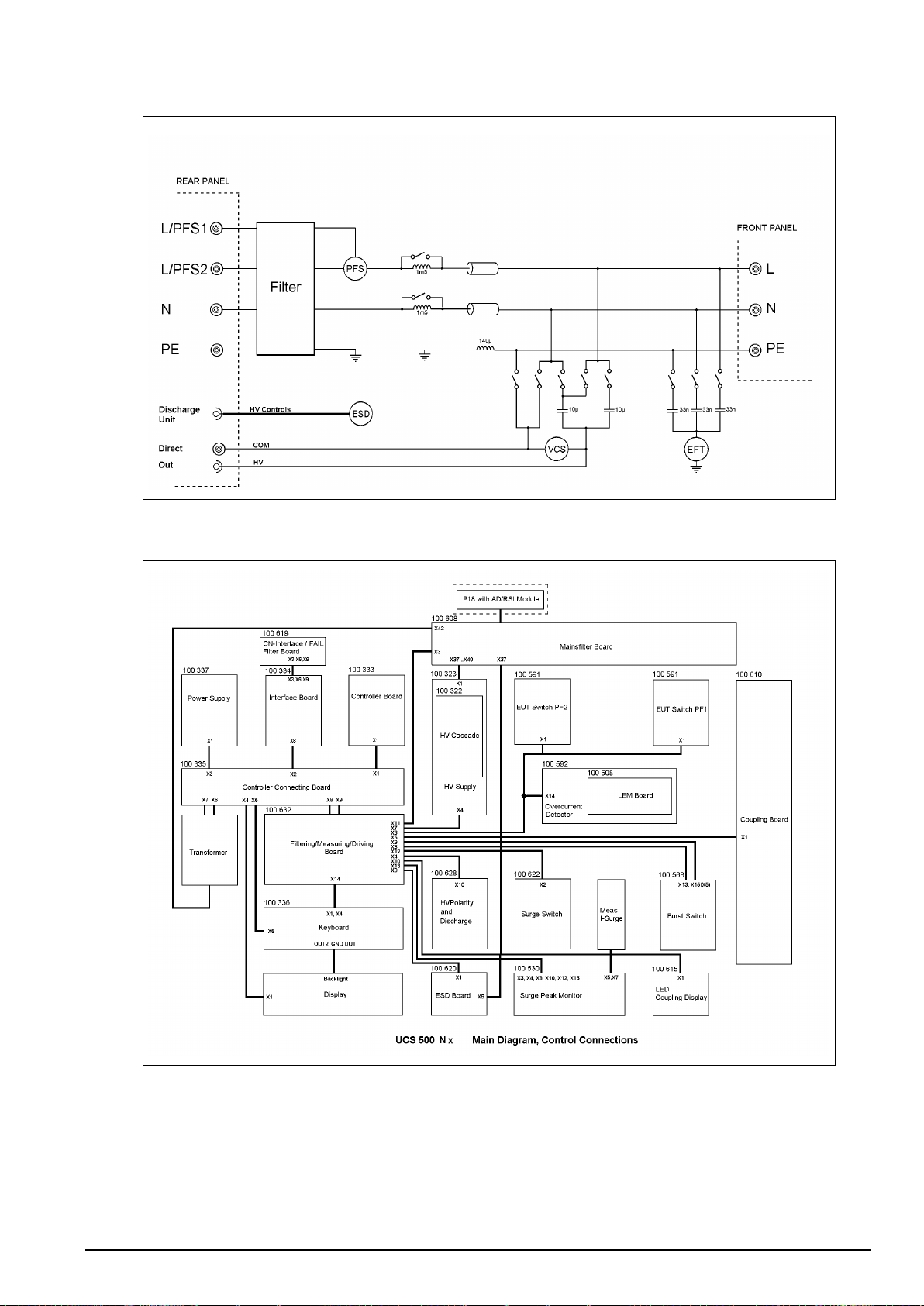
EM TEST UCS 500 Series
Operating Manual V 5.40 93 / 99
14.2.
UCS 500N - General Diagram
14.3.
Main diagram control connection

EM TEST UCS 500 Series
Operating Manual V 5.40 94 / 99
14.4.
Main diagram high voltage connection

EM TEST UCS 500 Series
Operating Manual V 5.40 95 / 99
14.5.
CNT 508N
The CNT 508N is a coupling network for coupling surge pulses to 8 lines via a 25 resistor. Depends from where
the pulse is adapted different waveshapes can be applied to the EUT.
14.5.1.
Operating elements
1 HV Output T1...T8
2 COM output
3 Earth bolt
4 COM input
5 HV input
14.5.2.
Technical data:
As per IEC 61000-4-5 and other relevant standards
Pulse 10/700s or 1.2/50s
Open circuit voltage
160V – 7,000V 10%
Serial resistor per output
25 ±10%
Number of parallel HV outputs
8
Number of COM outputs
2
Coupling
Channels
8 channels in parallel T1 to T8 with 25 each
Dimensions
Housing
19“, 3HU, 448x250x143mm
Weight
6.05 kg

EM TEST UCS 500 Series
Operating Manual V 5.40 96 / 99
14.5.3.
Main diagram
14.5.4.
Test Setup
14.5.5.
Accessories:
Screw set Earth cable
HV cable COM cable
8 (red) + 2 (black) EUT cables 2m

EM TEST UCS 500 Series
Operating Manual V 5.40 97 / 99
14.6.
CNT 516
The CNT 516 is a coupling network for coupling surge pulses to 16 lines via a 25 resistor. Depends from where
the pulse is adapted different waveshapes can be applied to the EUT.
14.6.1.
Operating elements
1 HV Output T1...T16
2 COM output
3 Earth bolt
4 COM input
5 HV input
14.6.2.
Technical data:
As per IEC 61000-4-5 and other relevant standards
Pulse 10/700s or 1.2/50s
Open circuit voltage
160V – 7,000V 10%
Serial resistor per output
25 ±10%
Number of parallel HV outputs
16
Number of COM outputs
3
Coupling
Channels
16 channels in parallel T1 to T16 with 25 each
Dimensions
Housing
19“, 3HU, 448x250x143mm
Weight
6.25kg

EM TEST UCS 500 Series
Operating Manual V 5.40 98 / 99
14.6.3.
Main diagram
14.6.4.
Test Setup
14.6.5.
Accessories:
Screw set Earth cable
HV cable COM cable
16 (red) + 3 (black) EUT cables 2m

EM TEST UCS 500 Series
Operating Manual V 5.40 99 / 99
14.7.
USB interface
USB interface “USB B” connector. For data transfer a USB interface is available. The internal RS 232
interface is converted to USB standard. Therefore, the user must set the same baud rate in the device and
control software.
Using the USB interface the user can have EMC problems during burst tests. Therefore, a high quality USB
cable (USB 2.0 standard) must be used.
The experience shows that usually the computer USB port is disturbed by interference’s. The ferrite FER-
USB reduces additional the interferences on the USB cable.
If there are still interferences, the whole test set-up with the wiring has to be reconsidered.
USB cable setup
The USB cable must be above ground with a
distance of at least 10 cm. Otherwise the cable can
be an antenna for the common mode burst pulses
and the communication may be influenced.
EM test provides a suitable ferrite as accessories
under the name UBS FER.
Best results are reached with 8 turns.
 Loading...