

Page 1
Shortform
dito & ditoControl
Version:
Replaces:
Filename:
Printdate:
Introduction
the benchmark for emc
Short manual for dito & ditoControl Software
(Version 1.20 )
Simulation of
Electrostatic
Discharges as per
IEC 61000-4-2,
ISO 10605 and
Related standards
2.04 / 16.06.2008
2.03 / 14.05.2008
Shortform introduction ditocontrol v203.DOC
16.06.08
Page 2

Table of Contents
1 dito: Operation ....................................................................................................................................3
1.1 dito: Starting up ..................................................................................................................................... 3
1.2 dito: Main Menu..................................................................................................................................... 4
1.3 dito: Starting with Easy ZAP .................................................................................................................. 5
1.4 dito: Easy ZAP menu............................................................................................................................. 6
1.5 dito: Other menus.................................................................................................................................. 7
2 DitoControl ..........................................................................................................................................8
3 Technical requirements ......................................................................................................................9
4 Installation / Uninstall .........................................................................................................................9
4.1 Installation............................................................................................................................................. 9
4.2 Remove ................................................................................................................................................ 9
5 Start ditoControl................................................................................................................................10
5.1 Connect the dito simulator via RS232-Interface ................................................................................... 11
5.2 Registration......................................................................................................................................... 12
5.3 Mode................................................................................................................................................... 12
5.3.1 Functions in Easy Mode ................................................................................................................. 12
5.3.2 Functions in Expert Mode in addition to Easy mode........................................................................ 13
5.4 Download of dito firmware ................................................................................................................... 14
5.5 Status bar............................................................................................................................................ 14
5.6 Input Protection ................................................................................................................................... 15
Page 3
EM Test ditoControl
After switching ON,
dito
starts a self test routine to check the
basic function of the unit including the high voltage power supply.
The R/C discharge parameters of the module are displayed in the
In case that there is no discharge module connected,
dito
will
By pressing the trigger button once again you can get into the
1 dito: Operation
1.1 dito: Starting up
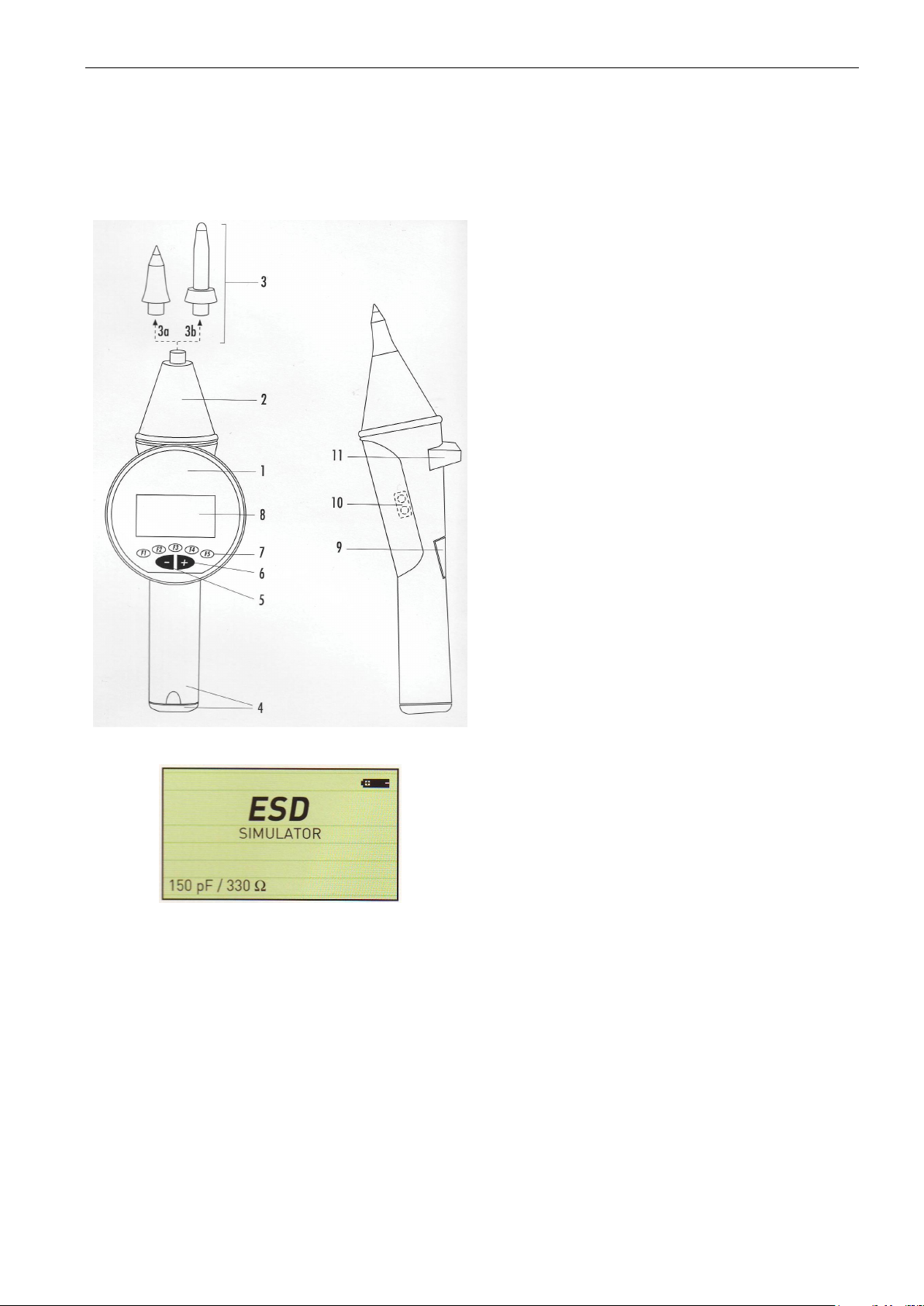
Parts 1
Operation 5
Connections 10 Optical Interface
Switching On – Switching Off
ON Push trigger button (9) once
OFF Push trigger button (9) for 3s
dito
base unit
2 Discharge Module
3 Discharge Tip
3a Contact discharge
3b Air discharge
4 Battery
Button
6
Button
7 Function keys F1...F5
8 Display
9 Trigger and ON/OFF
11 Ground Cable
Start-up Display
lower line.
show the message
No Discharge Module
main menu.
.
Short form Introduction V 2.04 3 / 15
Page 4
EM Test ditoControl
els”. After pressing Start, the operator can
tion keys and with
Within Quick Zap the test voltage can be
changed with the function keys
while running a test. With buttons the
polarity can be changed. The value U per
step can be selected in the Service Menu
This test routine helps to search for most
rate. This routine is normally not used for
the operator can preprogram on his own by
using the „ditoControl“ software. The data
can be downloaded via the optical interface.
The Standard Routines will guide the user
Hardware and software settings are made in
-
The standard test levels for AD and CD
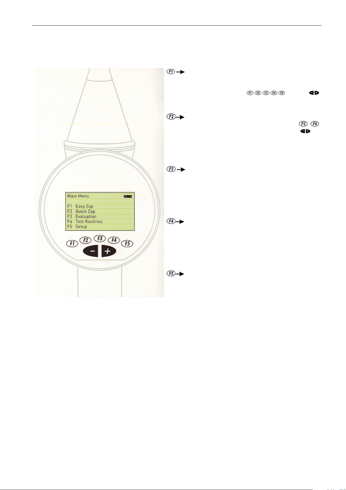
1.2 dito:
Main Menu
Easy ZAP
Quick ZAP
Evaluation
Easy Zap is based on “Standard Test Lev-
select the required test level with the func-
the polarity can be changed.
under Setting. Evaluation
sensitive test points at the DUT. The discharges are released with a higher repetition
final testing at the preselected test points.
Test Routines
Setup
The dito includes 8 standard routines, which
through the complete test procedure.
this menu.
can be set.
-
Hardware settings
- Firmware settings
Short form Introduction V 2.04 4 / 15
Page 5
EM Test ditoControl
1.3 dito: Starting with Easy ZAP
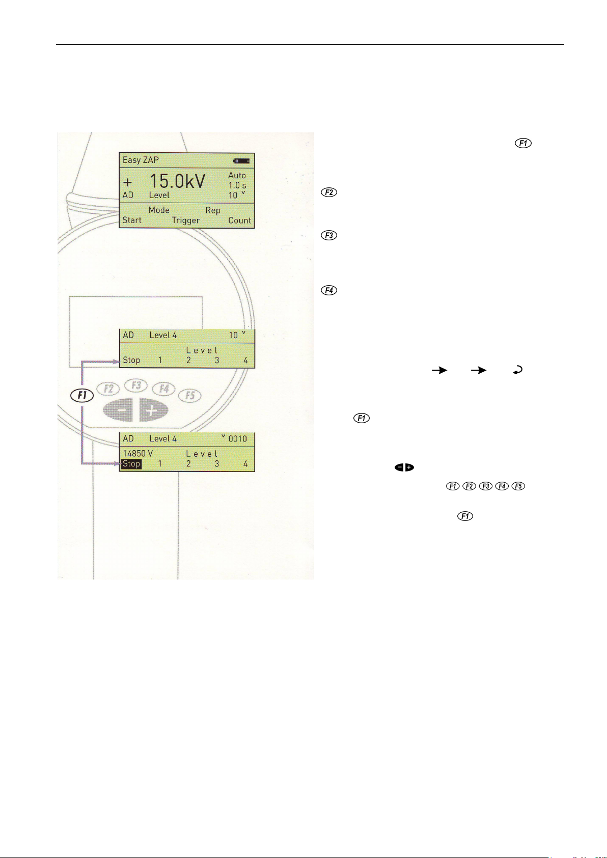
Easy ZAP
Select the menu Easy ZAP by pushing function key . With
Easy ZAP only predefined standard levels are tested.
Before the test is started, the operator has to select
the discharge mode,
CD
contact discharge ( discharge tip 3a) or
AD
air discharge ( discharge tip 3b)
the trigger mode,
Single
: single discharge,
Auto
: push once the trigger button [9] ,
Cont
: trigger button must be pressed all time
Rep
: the repetition rate of the discharges
Functions
Select : By pushing a function key several times, the operator
can change between different modes,
e.g. Trigger : Single Auto Cont .
Start : After all parameters are selected, the operator can
make dito ready for testing by pushing the function key
Start . The test itself is controlled by the trigger
button [9].
-
During the test, you can change polarity by
pressing .
-
With the function keys the operator can change the test level.
-
Pressing the function key Stop will stop the test
routine.
Short form Introduction V 2.04 5 / 15
Page 6
EM Test ditoControl
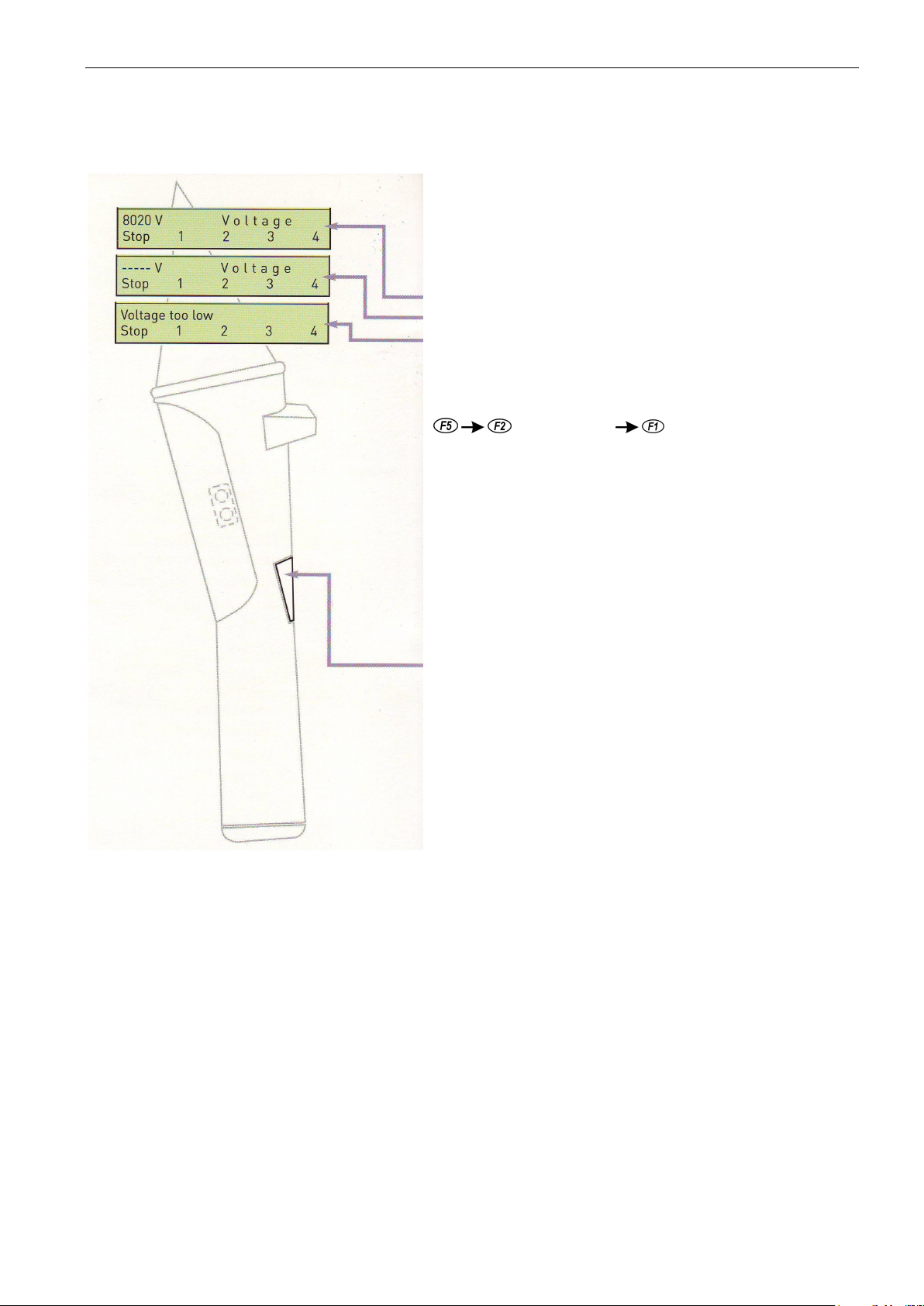
In case of air discharge mode the discharge may occur at any voltage
depending on the distance between the discharge tip and the DUT. This
charge occurs during the charging up procedure of dito. Therefore dito
Double-beep = Double beep always indicates warnings or failures e.g.:
- Pre-discharge ( air discharge occurred before
1.4 dito: Easy ZAP menu
may happen if the discharge tip is too close to the DUT and the dis-
shows you the following messages:
Discharge occurred after the preselected test voltage was reached ( normal case)
Discharge occurred between 50% and 100% of the preselected test voltage
Discharge occurred between 0% and 50% of the preselected test voltage
Acoustical signals
To enable the beeper select:
Hardware setting Key Beep = ON / OFF
Single-beep = Input confirmation if Key beep is ON
- No discharge Module
- No discharge relays available
- Battery voltage too low to generate high voltage.
the selected test voltage was reached)
- Test voltage not reached or not correct
Triple-beep = Test is finished;
dito
has shut down (switched OFF)
The Trigger button [ 9 ]
To switch ON: Press the Trigger button once
To switch OFF: Press the Trigger button [9] for 3s
Exception ( dito is in Start Mode )
To change the menus: Press the Trigger button once
To release discharges Single: Press Trigger button once
Cont : Discharging as long as the Trigger
button is pressed.
Auto: Press Trigger button once, the test runs
automatically. Pressing Trigger button
again stops the test procedure.
Short form Introduction V 2.04 6 / 15
Page 7
EM Test ditoControl
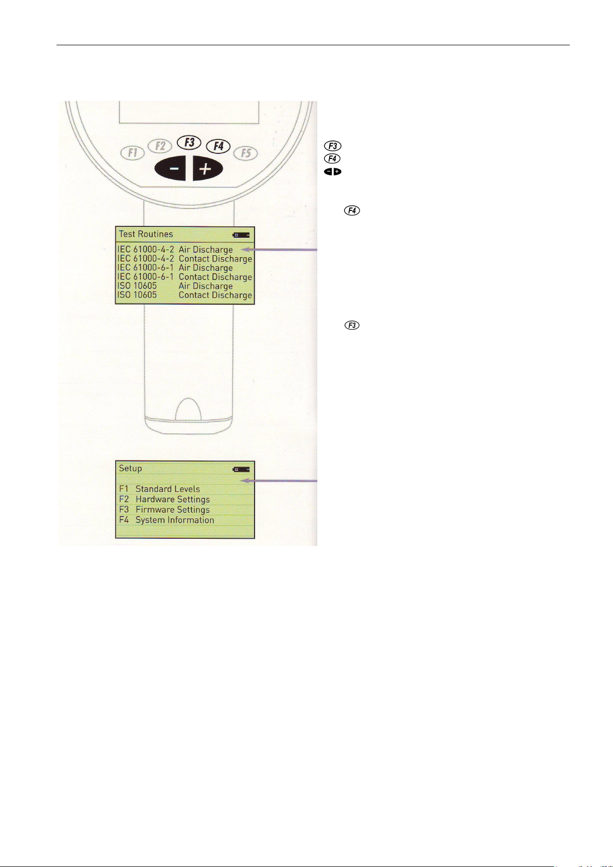
In Quick Zap Menu all parameters can be selected individually.
During a running test :the voltage can be increased by pushing
With the user can enter the menu
Evaluation
. This menu
can be used to check the DUT for most sensitive test points.
The preferred method to find these test points is air discharge
tion tests to apply a large number of repeatable discharges to a
specified test point. The preferred Trigger mode is
Auto
or
tion procedure, the operator can change the polarity and the
For detailed information related to the setup menu please read
1.5 dito: Other menus
Quick Zap Menu
decreases the voltage
increases the voltage
changes the polarity
Test Routines Menu
With the user can enter the menu Test Routines. 8 preprogrammable test routines can be stored. dito is delivered with 6
standard routines.
The test routines can be programmed in the ditoControl software which is available as an option. Via the optical interface
the test routines can be downloaded to dito. More information
please read in the dito and ditoControl manual.
Evaluation
AD
( discharge tip 3b ). Air discharges are continuously gener-
ated with a maximum repetition rate of 20Hz.
Contact mode CD ( discharge tip 3a ) is selected for long dura-
Continuous
All parameters can be selected individually. During the evalua-
test voltage.
.
Setup
the dito manual.
Firmware updates
Firmware updates can be downloaded via the optical interface.
Short form Introduction V 2.04 7 / 15
Page 8
EM Test ditoControl
2 DitoControl
ditoControl
Short manual for ditoControl software
(Version 1.20 )
ditoControl is not only a software to control dito and to perform ESD tests automatically, but it is a software
which manages the office work as well as the test itself. The following important steps are covered:
Office work (preparation of the test)
Making „Test Notes“ as preparation for the real test
Description of the DUT
Specification of the test points based on a picture of the DUT.
Description of functions and failure criteria of the DUT.
Specification of the test parameters and the test routine
Specification of auxiliary equipment and special test software used in this test.
Print out of the Test Notes. This document is used to support the operator during the running test.
Comments which are important can be written into and can be added later on into the test report.
Generation of test routines
Based on the Test Notes the test parameters are fixed.
Preprogrammed the test routines based on the data in Test Notes.
The different test routines can be managed by ditoControl (library)
Standard test routines and standard libraries can be built up.
The complete test preparation is made. All data are available on the computer
Laboratory work.
Make dito ready for testing.
dito is connected to the computer and ditoControl is started.
The preprogrammed test files are downloaded to dito. If necessary or useful all other test routines
which are available in dito can be deleted.
The operator can only perform tests for which the related test routines are available. False operation by
the user therefore are not possible.
The operator performs the test at the DUT.
All test data of the actual test are stored in dito.
In case of failures at the DUT the operator can set Fail-Flags, which also are stored in dito.
Comments related to these Fail-Flags can be added manually to the Test Notes and can be later on
entered to the test report at the right place. All Fail-Flags are indicated in the test report.
Office work.
The operator generates a test report.
After the test is finished dito will be connected again to the computer. All test data stored in dito will be
uploaded and are the basis for the test report.
ditoControl automatically generates the test report.
The generated document can be converted into almost all other formats.
Custom specific logos and pictures can be implemented.
The documents and the used test routines can be directly emailed to other dito users or laboratories.
Short form Introduction V 2.04 8 / 15
Page 9
EM Test ditoControl
3 Technical requirements
Computer PC Pentium or higher
Monitor
Disc drives CD-ROM for installation
Mouse
Interface RS232 Com1/ 2 / 3 / 4
Operation System Win9x / Windows Me / Windows2000 / Windows NT
Hard disk space ditoControl, needs approx. 20MB on the hard disc
Cable to dito Connecting cable RS232 with optical link
VGA 800*600, 16 Mio. Colors, Small Font
4 Installation / Uninstall
Start MS-Windows.
Insert the CD in the CD-ROM drive of your computer.
4.1 Installation
If you have turned off Auto-run, double-click the file named Setup.exe in root directory of ditoControl CD. This
launches the installation that will guide you through installation of ditoControl on your hard disk. If Auto-run is
turned on, the Setup program will be loaded automatically, when you insert ditoControl CD.
4.2 Remove
Choose in the starter menu
„System control „
„-> Software“
„-> Remove of Software “
Click on „uninstall“ and the de-installation starts automatically. In case that some files will not be deleted aut omatically, it might be necessary to remove the directory DITOCONTROL with the help of a file manager.
Short form Introduction V 2.04 9 / 15
Page 10
EM Test ditoControl
5 Start ditoControl
Start MS-Windows.
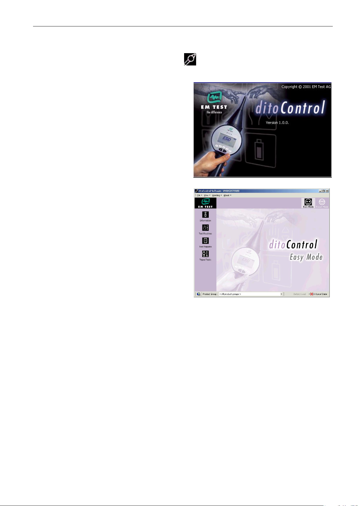
Start ditoControl, double-click on the ditoControl -Icon.
The startup screen appears for approx. 2s.
After that ditoControl shows up on the desktop.
Short form Introduction V 2.04 10 / 15
Page 11
EM Test ditoControl
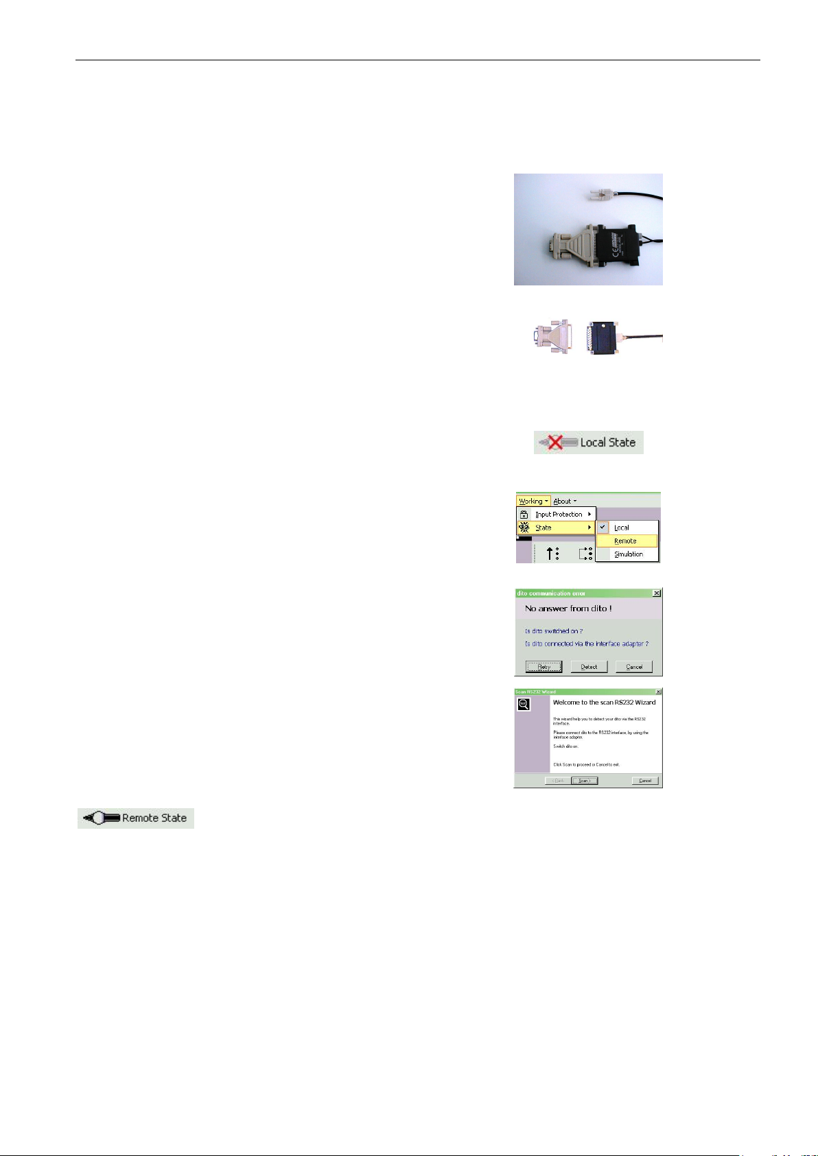
Switch dito on or go to the start menu (double
In case that no communication is possible it is
recommended to go back to the start menu or
switch on/off the dito. This is not a failure but
Connect the IFA interface adapter to the RS232
It can also be set into remote by selecting the
If for the first time no communication is possible
Select know the button Detect to start the RS232
The RS232 Wizard now automatically scans for
At the end of the wizard dito should be detected.
5.1 Connect the dito simulator via RS232-Interface
Connection between dito and computer is done by RS232 interface via optical link.
The following steps are necessary :
Connect the RS232 optical link to dito.
click on dito trigger button).
a wanted procedure.
connector of the computer.
Start ditoControl (see above).
Set dito into remote via software.
The initial status of the dito is local. It can be set
into remote by clicking onto the state button in the
status bar and selection of Remote.
menu <Working><State><Remote>.
It is not necessary to set the baud rate, because ditoControl checks the RS232 parameter.
the following dialog will appear.
Wizard.
the connected dito.
If not, please check all points above.
In case that communication works, dito is in Remote and ditoControl shows the status.
ditoControl can simulate the dito simulator. For this mode please select <Working><State> <Simulation>.
Short form Introduction V 2.04 11 / 15
Page 12
EM Test ditoControl
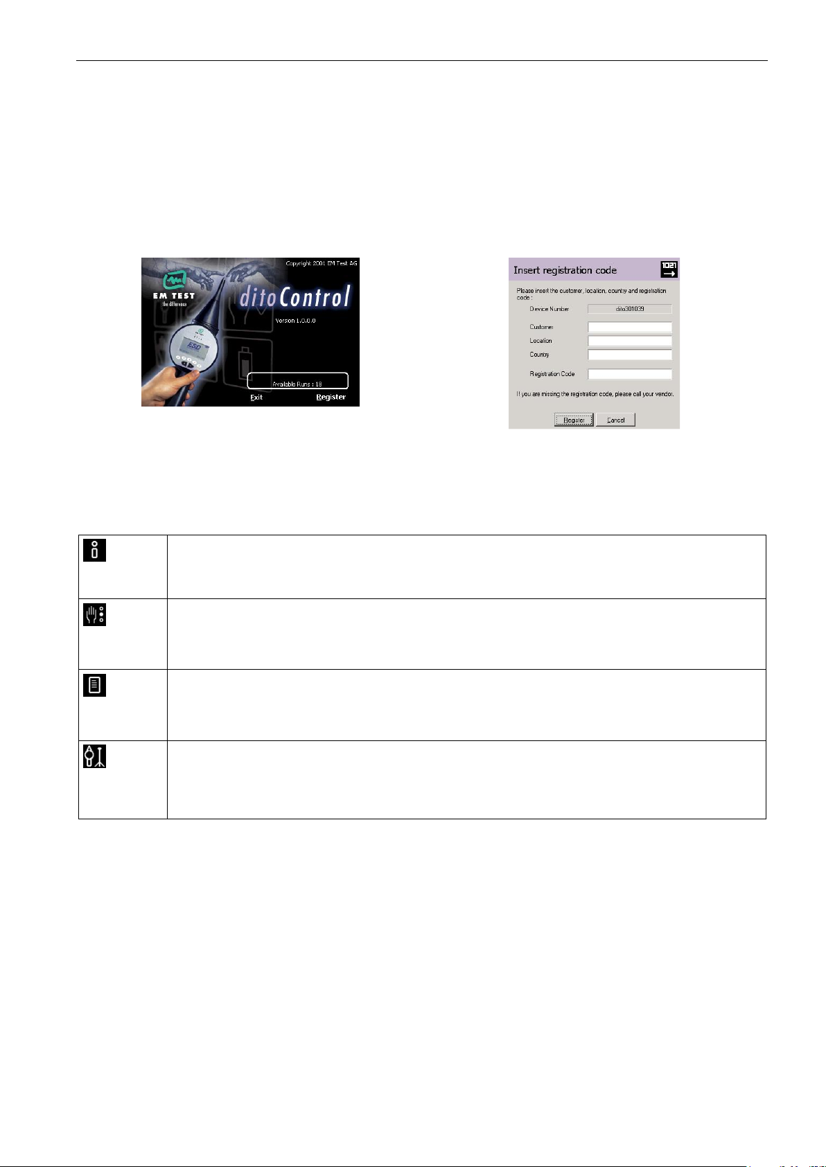
The operator gets information how to generate test procedures or how to conduct a tripod
A tripod test can be performed with dito. The parameters can be defined manually or based on
a standard with different test levels. It is also possible to execute a voltage sweep, with start to
5.2 Registration
After a successful installation of ditoControl, it is necessary to register the software.
If the software is not registrated correctly, the operator can use it twenty times. After that a registration code
must be inserted, otherwise the software can no more be used. For registration code please call factory or the
responsible sales office.
For registration please select the menu <About><Info and Registration> and then click on Register. The register dialog will now appear. Please insert the requested data and press the button Register.
During the registration it is necessary to connect the dito simulator, because the registration code is related
to the actual dito device number.
5.3 Mode
ditoControl supports two different operation modes, Easy and Expert mode.
For more information please refer to the information window or the application note.
5.3.1 Functions in Easy Mode
Information
test.
Test Routines
They are preprogrammable and can be download to dito.
The test routines can be imported or exported.
Test Report
The test data can be uploaded from dito after a test is finished.
A wizard guides you through the generation of a test report
Tripod Test
stop voltage in certain voltage steps.
Short form Introduction V 2.04 12 / 15
Page 13
EM Test ditoControl
As part of ditoControl, a database of standards is available. New standards can be created
A product database can be defined, including pictures of the test setup and DUT. These
The header of the printed document can be defined in Report Header Presetting. Text and
In Test Notes, different test parameters can be predefined. The test notes can be printed and
dard with different test levels. It is also possible to execute a voltage sweep with start to stop
An application note for generating test notes, test routines and test report is available and can
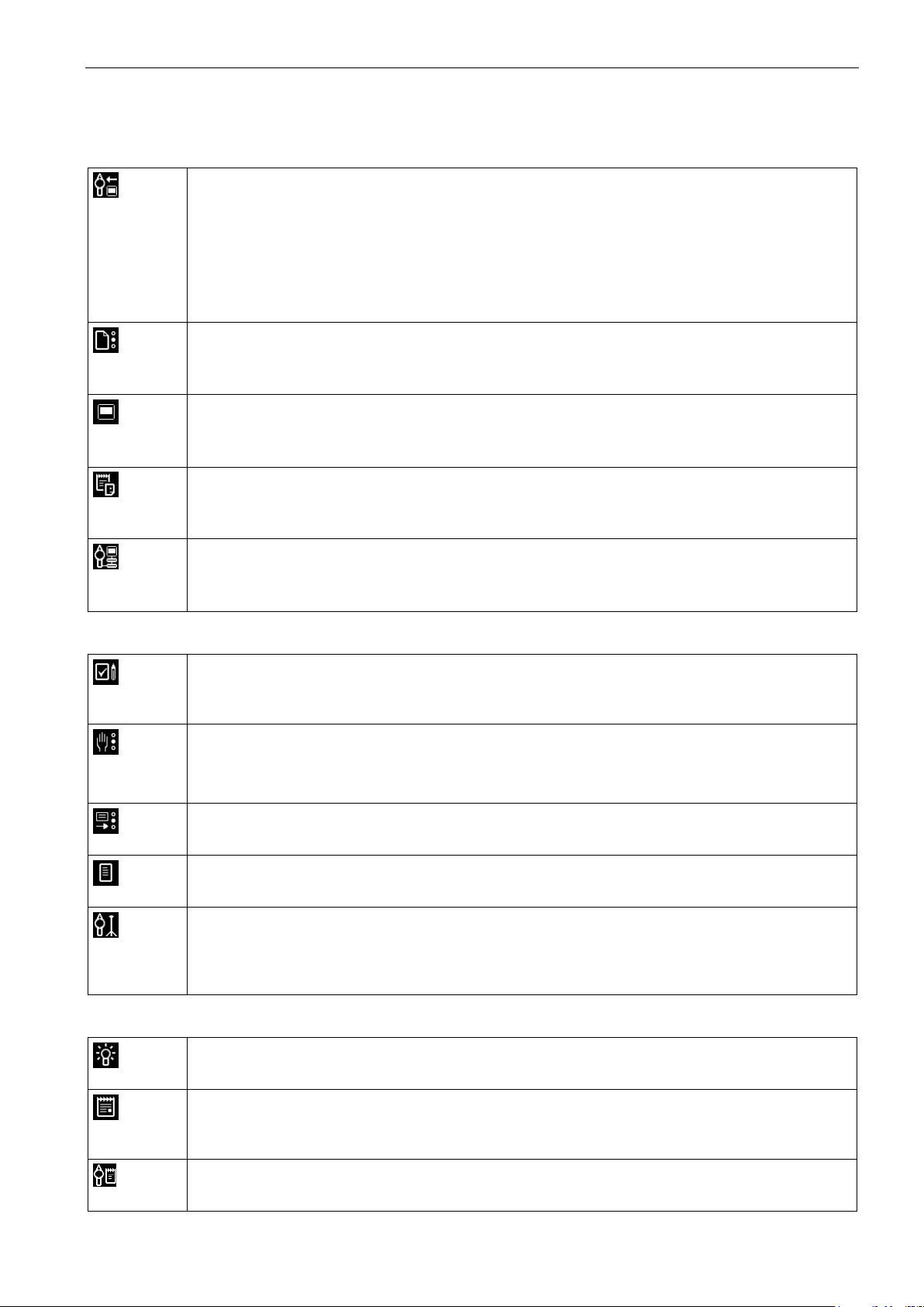
5.3.2 Functions in Expert Mode in addition to Easy mode
Configuration
Simulator
The serial number can be downloaded to dito.
For customer specific discharge modules the values for the R/C network can be entered.
New firmware can be downloaded to dito from ditoControl.
The calibration date can be entered
User adjustments to the factory setting can be done.
Standard
or modified.
Test Objects / Products
data can be inserted into the Test Notes and Test Reports.
Report Headers
Testing
Logo can be inserted.
Auxiliary Equipment
For an ESD test auxiliary equipment might possibly to be used. These devices can be de-
scribed in Auxiliary Equipment and linked into the test report.
Test Notes
used as guide during the ESD test.
Test Routines
The test routines stored in dito can be uploaded.
Test routines can be generated based on the information of a test note.
Test Results
Test results can be uploaded from dito and used for the generation of a test report.
Test Report
The test report can be created by using the information of a test note.
Tripod Test
A tripod test can be performed. The parameters can be defined manually or based on a stan-
voltage with predefined voltage steps.
Information
Test Procedure
The Test procedure describes different steps for a manual or tripod test.
Application Note
be printed out.
dito Manual
The dito Instruction Manual is available in ditoControl and can be printed out.
Short form Introduction V 2.04 13 / 15
Page 14
EM Test ditoControl
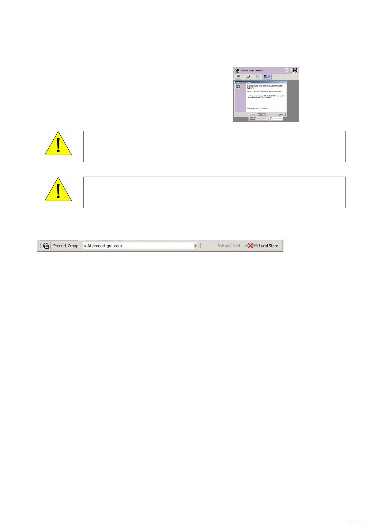
For this select the menu <Configuration Device>
Download must be made with a RS232 Interface only. Using an USB to RS232 interface will
not deliver enough power to the optical link. Therefore the datatransfer will fail and dito will
not install the new firmware and can not be operated furthermore. The unit has to be send
Before operating the download check the battery condition of the dito simulator. At first the
tion is interrupted or the battery charge gets too low, dito can not be operated furthermore.
5.4 Download of dito firmware
New version of firmware can be easy downloaded with ditoControl.
Firmware.
A wizard will guide you through the download.
All relevant points are described in the wizard.
WARNING
WARNING
back to factory or to the responsible sales office.
installed firmware will be erased. In case that afterwards dito is switched off, the communic a-
The unit has to be send back to factory or to the responsible sales office.
5.5 Status bar
The functions in the status bar are :
Product Group
Selection of product groups which are used for generating test routines, test notes and test reports, and
also for the tripod test.
The product group determines the selectable standard area in the different wizards.
Battery Load
Indication of battery charge condition.
State of dito
Indication Local or Remote status of dito
Short form Introduction V 2.04 14 / 15
Page 15
EM Test ditoControl
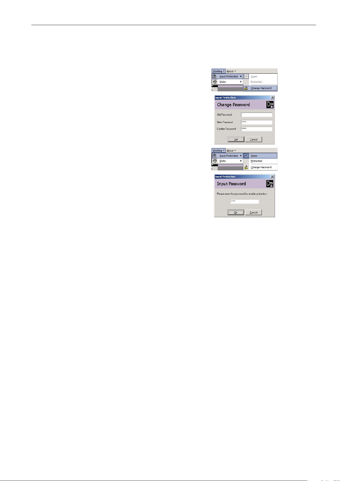
To activate the input protection please select the
menu <Working><Input Protection><Change
The switching between Open and Protected can
5.6 Input Protection
Some data can be password protected.
In this case the predefined test routines and standards can not be modified.
Password>.
Then enter the password.
be done in menu <Working><Input Protection>
Please insert the password to enable the protec-
tion.
Short form Introduction V 2.04 15 / 15
 Loading...