


M a n u a l
F o r O p e r a t i o n
AutoWave
Portable solution to simulate and
measure Battery Supply Voltage
Variation
FM Version ≥ 5.09.00
The Automotive industry is facing the necessity to investigate
the behavior of the battery voltage variations and their effects to
electronic components connected to the supply network of the
cars, testing emission and immunity.
The two major international standards describing test
procedures to simulate different phenomena’s related to the
battery supply lines are ISO 16750-2 for 12V and 24V supply
voltages and ISO 21848-2 for 42V supply voltage.
ISO 7637-2
ISO 16750-2
ISO 21848-2
SAE J1113
Manufacturer spec as
per GM, Ford, Chrysler,
Mercedes, BMW, VW,
PSA, Renault, Fiat ......
the benchmark for emc
Version:
5.9.1/ 29.02.2016
Replaces:
5.9.0/ 03.02.2016
Filename:
UserManual-AutoWave-E-V5.9.1.doc
Printdate:
29.02.16

EM TEST AutoWave
EM TEST Switzerland GmbH
Sternenhofstrasse 15
4153 Reinach BL1
Switzerland
Phone : +41 61 717 91 91
Fax : +41 61 717 91 99
URL : http://www.emtest.com
Copyright © 2016 EM TEST Switzerland GmbH
All right reserved.
Specifications subject to change
Manual for Operation V 5.9.1 2 / 45

EM TEST AutoWave
Foreword
Thank you for purchasing the AutoWave generator. This user’s manual lists
precautions that must be taken during use, and contains useful information about
the functions and operating procedure of the device. To ensure correct use,
please read this manual thoroughly before beginning operation. After reading the
manual, keep it in a convenient location for quick reference whenever a question
arises during operation.
This manual contains a selection of typical system setup with the correct wiring
diagram.
For information about using and handling with the software AutoWaveControl,
see the manual for this product
Notes
The contains of this manual are subject to change without prior notice as a result
of continuing improvements to the instrument’s performance and functions. The
figures given in this manual may differ from those that actually appear on your
display and screen.
Every effort has been made in the preparation of this manual to ensure the
accuracy of this contents. Should you have any questions or find any errors,
please contact your EM Test representative or send an email to EM Test.
Copying or reproducing all or any part of the contents of this manual without the
permission of EM Test is strictly prohibited.
Trademarks
Microsoft, Windows, Windows NT, Windows Me, Windows XP and Vista are
either registered trademarks or trademarks of Microsoft Corporation in the United
States and/or other countries.
Other company and product names are trademarks or registered trademarks of
their respective companies
For purpose of this manual, the TM and ® symbols do not accompany their
respective names or registered trademark names.
Version
This manual is written for AutoWave Firmware version 5.09.00 and higher
Manual for Operation V 5.9.1 3 / 45

EM TEST AutoWave
Content
1. Model Overview ............................................................................................................... 5
1.1. AutoWave Model and extension modules .......................................................................................... 5
2. Put in service Functions ................................................................................................. 6
2.1. Front view ........................................................................................................................................... 6
2.2. Rear view ............................................................................................................................................ 8
2.3. Put in service .................................................................................................................................... 13
2.3.1. Unpacking ......................................................................................................................................... 13
2.3.2. Installation in a System ..................................................................................................................... 13
2.3.3. Hardware wiring ................................................................................................................................ 14
3. Operation ....................................................................................................................... 24
3.1. Power on ........................................................................................................................................... 24
3.2. Menu structure .................................................................................................................................. 24
3.2.1. Mode Menu ....................................................................................................................................... 24
3.2.2. Setup Menu ...................................................................................................................................... 29
3.2.3. DC Source ........................................................................................................................................ 30
3.2.4. Sample frequency (only with the option record) ............................................................................... 31
3.2.5. Input Range (only with the option record) ........................................................................................ 31
3.2.6. Trigger .............................................................................................................................................. 31
3.2.7. DUT Monitor ..................................................................................................................................... 32
3.2.8. GPIB Address ................................................................................................................................... 32
3.2.9. Ethernet IP- Address ........................................................................................................................ 32
3.2.10. Ethernet Netmask ............................................................................................................................. 32
3.2.11. Ethernet Gateway ............................................................................................................................. 32
3.2.12. Date .................................................................................................................................................. 33
3.2.13. Time .................................................................................................................................................. 33
3.2.14. LCD Contrast .................................................................................................................................... 33
3.2.15. Language .......................................................................................................................................... 33
4. Test Equipment ............................................................................................................. 34
5. Technical data ............................................................................................................... 35
6. Maintenance ................................................................................................................... 37
6.1. General ............................................................................................................................................. 37
6.2. Calibration and Verification ............................................................................................................... 37
6.2.1. Factory calibration ............................................................................................................................ 37
6.2.2. Guideline to determine the calibration period of EM Test instrumentation ...................................... 37
6.2.3. Calibration of Accessories made by passive components only: ...................................................... 37
6.2.4. Periodically In-house verification ...................................................................................................... 37
6.3. Calibration ......................................................................................................................................... 38
6.4. Verification ........................................................................................................................................ 38
7. Delivery Groups ............................................................................................................. 38
7.1. Basic equipment ............................................................................................................................... 38
7.2. Accessories and options ................................................................................................................... 38
7.2.1. Extension Board ............................................................................................................................... 38
7.3. Useful Accessories ........................................................................................................................... 39
7.3.1. Hi-Speed USB 2.0 Fast Ethernet Adapter installation ...................................................................... 39
8. Annex ............................................................................................................................. 40
8.1. Update a new Firmware ................................................................................................................... 40
8.2. Basic Waves ..................................................................................................................................... 42
8.3. Declaration of CE-Conformity ........................................................................................................... 44
8.4. AutoWave - General Diagram .......................................................................................................... 45
Manual for Operation V 5.9.1 4 / 45

EM TEST AutoWave
1.
1.1.
Module
includes
WaveGenerator
- On-Board Supply Simulator with Dual Channel outputs for dc
source control.
- WaveControl software to generate wave shapes based on
segments, point to point matrix.
- Controller with internal hard disk.
Modules
Extension Board
Extension board with
- 2 additional output channels ( Play )
- 2 measuring input channels ( Record )
- Functions to measure, record & play data of on-board supply
systems.
WaveRecorder
Software Module to support, record and replay functions.
Up and download support, waveform editing and report generator
function
The WaveRecorder requires the position Extension Board
Model Overview
AutoWave Model and extension modules
Basic model
Extensions
Manual for Operation V 5.9.1 5 / 45

EM TEST AutoWave
2.
2.1.
1 LED Power
2 LED Running
3 LED Trigger
4 Mode
5 Start
6 Stop
7 Cursor "" ""
8 Setup
9 LED display output channels 1...4
10 LED display input channels 1...2
11 Input channel 1 & 2 ( option )
12 Display
The LED power indicates the power on status.
The LED Running indicates the running play- or
measuring status
The LED Trigger indicates
- Manual, external or remote trigger event
- Start of a sequence
Pressing this button will cyclicly rotate between the main
menus.
- Wave Generator
- Wave Recorder
- Wave Manager
Start and Stop button for measurement and running
arbitrary waves.
START : “Start” or “Continue” a measurement or a
running Arbwave.
STOP : Stops a measurement or a running
Arbwave
2nd STOP : Exit the record or play function
Put in service Functions
Front view
1. LED power
2. LED Running
3. LED Trigger
4. Mode
5. Start / Stop
Manual for Operation V 5.9.1 6 / 45

EM TEST AutoWave
Cursor Key with the following functions
- Scrolling in the menus
- Setting the values up / down
Menu button for the device configuration menu.
See Chapter
3.2.2. Setup
Menu
LED display for indicating the active output channels.
Depends of extension 2 or 4 channels are built in.
Example:
CH 1 : Default channel for the battery power supply.
CH 2 : Auxiliary DC power for dips
CH 3 : Auxiliary channel for Ford specs.
CH 4 : Auxiliary channel for Ford specs.
The LED indicates the state of the measuring channel
CH1 and CH2.
LED Status
OFF : Standby
ON : Recording
Input plugs for the two measuring channels CH1 and
CH2
Maximum input voltage is 200V peak - peak
LCD display 2 x 40 characters
6. Cursor key "" ""
7. Setup
8. LED output active channel CH1 to CH4
9. LED display input channel 1 + 2
10. Measuring input channel 1 + 2
11. Display
Manual for Operation V 5.9.1 7 / 45

EM TEST AutoWave
2.2.
1 Output channel 1...4
2 Framebus IN / OUT
3 CAN port
4 Ethernet port
5 USB port
6 GPIB / IEEE 488 port
7 Fuse F1 DC 3.15A
8 Fuse F2 AC 1A
9 Mains 90V – 250V
10 Trigger IN1 / IN2
11 Trigger OUT1 / OUT2
12 DUT monitor
13 DC supply 12 – 32V
14 Power on switch
BNC output plug to controll external DC sources.
Example:
CH 1 : Default channel for the battery power supply.
CH 2 : Auxiliary DC power for dips
CH 3 : Auxiliary channel for Ford specs.
CH 4 : Auxiliary channel for Ford specs.
Output range:10V
Impedance 50Ω
Daisy Chain bus with Sub D 15 poles male and
female connectors.
This port is used as communication and control bus
between EM Test devices.
Rear view
1. Output Channel 1...4
2. Framebus IN / OUT
Manual for Operation V 5.9.1 8 / 45

EM TEST AutoWave
CAN port 9 pole Sub D female connector
The Philips PCA82C251 CAN transceiver for 24V
system serves as the interface between the CAN
protocol controller and the physical bus. It is primarily
intended for applications (up to 1 Mbaud)
The CAN- BUS is function is inactive
Pin assignment
1: nc
2: CAN_L
3: CAN GND
4: nc
5: CAN SHLD
6: CAN GND B
7: CAN_H
8: nc
9: +VCAN
The network controller supports a 10 / 100BaseTinterface. The device auto-negotiates the use of a
10Mbit/sec or 100Mbit/sec connection.
Pin assignment
1: TXD+
2: TXD
3: RXD+
4: RXD-
USB memory port for data transfer to or from a
memory stick.
The power contacts for USB devices are not protected. They are
suitable to supply connected USB devices with a maximum of
500mA power dissipation. Don’t supply external USB devices
with a higher power dissipation through this interface.
Pin assignment
1: GND
2: +DATA
3: -DATA
4: VCC
Parallel interface GPIB / IEEE 488, IEEE 488
interface with IEEE connector.
Fuse F1 for DC power supply
Fuse type : 3.15 slow blow
Dimension : 5 x 20mm
Fuse F1 for AC power supply
Fuse type : 1A slow blow
Dimension : 5 x 20mm
3. CAN port
4. Ethernet port
5. USB port
6. GPIB / IEEE 488 port
7. Fuse F1
8. Fuse F2
Manual for Operation V 5.9.1 9 / 45

EM TEST AutoWave
The plug is part of the mains filter. ( 90 - 250V / 1A )
Start Stop
Trigger input for event triggering. This trigger inputs
are connected directly to the DSP signal processor.
Input Signal : Negative slope
Input Function Remarks
Trigger IN 1 : Wave start
Trigger IN 2 : Wave stop ( Vers. >1.30)
Proposal design of external circuit for using positive
edge trigger signal.
External trigger circuit Trigger Input
9. Mains input
10. Trigger IN
Manual for Operation V 5.9.1 10 / 45

EM TEST AutoWave
Trigger outputs for event triggering. This
trigger outputs are generated from the DSP
signal processor.
Max. voltage: 24V ( pull up )
Current : 100mA
NOTE : For use the trigger out the user has
to connect an external DC source
for pull up the trigger signal
Trigger OUT at Start
Trigger OUT at Stop
Trigger OUT at Event
Trigger OUT at Break
Trigger OUT at each Iteration
11. Trigger OUT
Manual for Operation V 5.9.1 11 / 45

EM TEST AutoWave
DUT monitor for any fail detection.
DUT Monitor 1:
DUT Monitor 2:
Function:
Input signal: Negative slope.
NOTE : The signal must be released to high before
you start the next wave. The test will start
and does not stop if the monitor signal is at
low level during the wave start
Settings
The DUT monitor is settable in the AutoWave
software and has the following function
Disabled no function
Stop stops immediately the wave
Notify send a message to DUT Log file
NOTE : The output voltage after a stop event
depends on the setting of the end voltage
parameter:
YES V= Set end voltage
NO V keeps at the actual voltage
Plugs for dc power supply like a car battery. The
output is protected against reverse battery
polarization.
DC input voltage range : 12V – 32V dc
Power ON switch for AutoWave. The system needs
approx. 35 seconds for booting.
12. DUT monitor
13. DC input
14. Power on switch
Manual for Operation V 5.9.1 12 / 45

EM TEST AutoWave
2.3.
2.3.1.
2.3.2.
2.3.2.1.
1. Unlock the two knobs on the front side and pull out the drawer
2. Mount the AutoWave into the four bolts. This fixation will allow the user
to uncase the equipment in a short time for external use.
3. Connect the cables to the AutoWave
Output CH1 to CH4 BNC
Mains 115...230V
Interface IEEE / GPIB
Ethernet if available
Trigger IN / OUT BNC ( if available )
DUT Monitor BNC ( if available )
4. Final work
- check the proper cabling
- insert the drawer
- fix the two knobs
Put in service
Unpacking
Please check if the packing is not damaged. If there is an external damage, make inform your representative.
Installation in a System
The AutoWave is used to control one or more DC sources and / or for measuring and recording of the transient
behavior of a voltage during a sequence.
Installation or mount in a 19” Rack
Manual for Operation V 5.9.1 13 / 45

EM TEST AutoWave
2.3.3.
Connection to
A : Rack with ISO equipment ( IEEE )
B : Stand alone equipment ( Ethernet )
iso.control software uses the IEEE interface. Ethernet is not supported by iso.control
When setting up the test national and international regulations
regarding human safety have to be guaranteed.
It is recommended to connect the simulator to the ground reference
plane of the test set-up.
The generators of the series 200, UCS, LD, PFS and VDS can be
linked together to a fully automotive test set-up.
The set-up communicates via the IEEE/GPIB bus and is controlled by
ISM ISO software.
For setting up the system see the following figures:
Each generator can be operated individually as a single equipment.
Hardware wiring
There are two solutions to connect the computer to the AutoWave.
- IEEE connection
- Ethernet connection
Both interface connections are applicable. Depends of the implementation EM Test propose the
IEEE or Ethernet interface.
iso.control software uses the IEEE interface. Ethernet interface is not supported by iso.control.
Manual for Operation V 5.9.1 14 / 45

EM TEST AutoWave
2.3.3.1.
Setup example with:
AutoWave
UCS 200
VDS 200N
LD200
Devices Wiring
Wiring
Manual for Operation V 5.9.1 15 / 45

EM TEST AutoWave
Setup example with:
AutoWave
UCS 200
VDS 200N
LD200
PFS 200
RDS 200
Note : Do never connect The PFS200 output 0-10V in parallel with any AutoWave output. In this
case the controlled DC source will deliver a wrong output signal. It is not allowed to
connect two output sources in parallel.
Devices Wiring
Supply connections from VDS200 to UCS200 and PFS200 can be wired inside the rack.
Manual for Operation V 5.9.1 16 / 45

EM TEST AutoWave
Setup 3:
example with:
Rack 1
RDS 200
RDS 200
RDS 200
AutoWave
PFS 200N
VDS 200N
Rack 2
LD 200N
UCS 200N
This configuration is suitable for testing Ford AC CI-230 tests with four waves at the
same time. The figure shows the output for:
- General tests at UCS output
- Dips and Drops at PFS 200
- Ford AC CI-230 at RDS and VDS outputs
Note : The default connection between the two racks is
Test Supply Out VDS – Test Supply IN PFS.
Dips and Drops are available on UCS 200 output, when the connection
Test Supply out PFS is used. The disadvantage is the additional voltage drop
inside the UCS 200.
Supply connections from VDS200Nx to PFS200N can be wired inside the rack.
Automotive rack for with 4 DC output for Ford AC CI-230 test
Manual for Operation V 5.9.1 17 / 45

EM TEST AutoWave
Setup 4:
example with:
Rack
MPG 200
LD 200
PFS200
VDS 200N
EFT 200
CNA 200
AutoWave for replace
ARB 2714
Manual for Operation V 5.9.1 18 / 45

EM TEST AutoWave
2.3.3.2.
Setup 5:
example with:
Rack
LD 200N
AMP 200N
AutoWave
UCS 200N
VDS 200N
Wiring examples with AMP 200
Manual for Operation V 5.9.1 19 / 45

EM TEST AutoWave
Setup 7:
example with:
Rack 1
RDS 200
RDS 200
RDS 200
AMP 200N
AutoWave
PFS 200N
VDS 200N
Rack 2
LD 200N
UCS 200N
Setup 8:
example with:
Rack 1
RDS 200
RDS 200
AMP 200N
AutoWave
PFS 200N
VDS 200N
Rack 2
LD 200N
UCS 200N
Manual for Operation V 5.9.1 20 / 45

EM TEST AutoWave
2.3.3.3.
Setup 11:
example with:
Rack
AutoWave
PFM 200N100
VDS 200N
Setup with PFM 200N100
Manual for Operation V 5.9.1 21 / 45

EM TEST AutoWave
2.3.3.4.
Setup 12:
example with:
Rack
AutoWave
PFM 200N100
VDS 200Q 25, Q 50
External : AMP 200
Setup with AutoWave and VDS 200Q and PFM 200N100
Manual for Operation V 5.9.1 22 / 45
EM TEST AutoWave
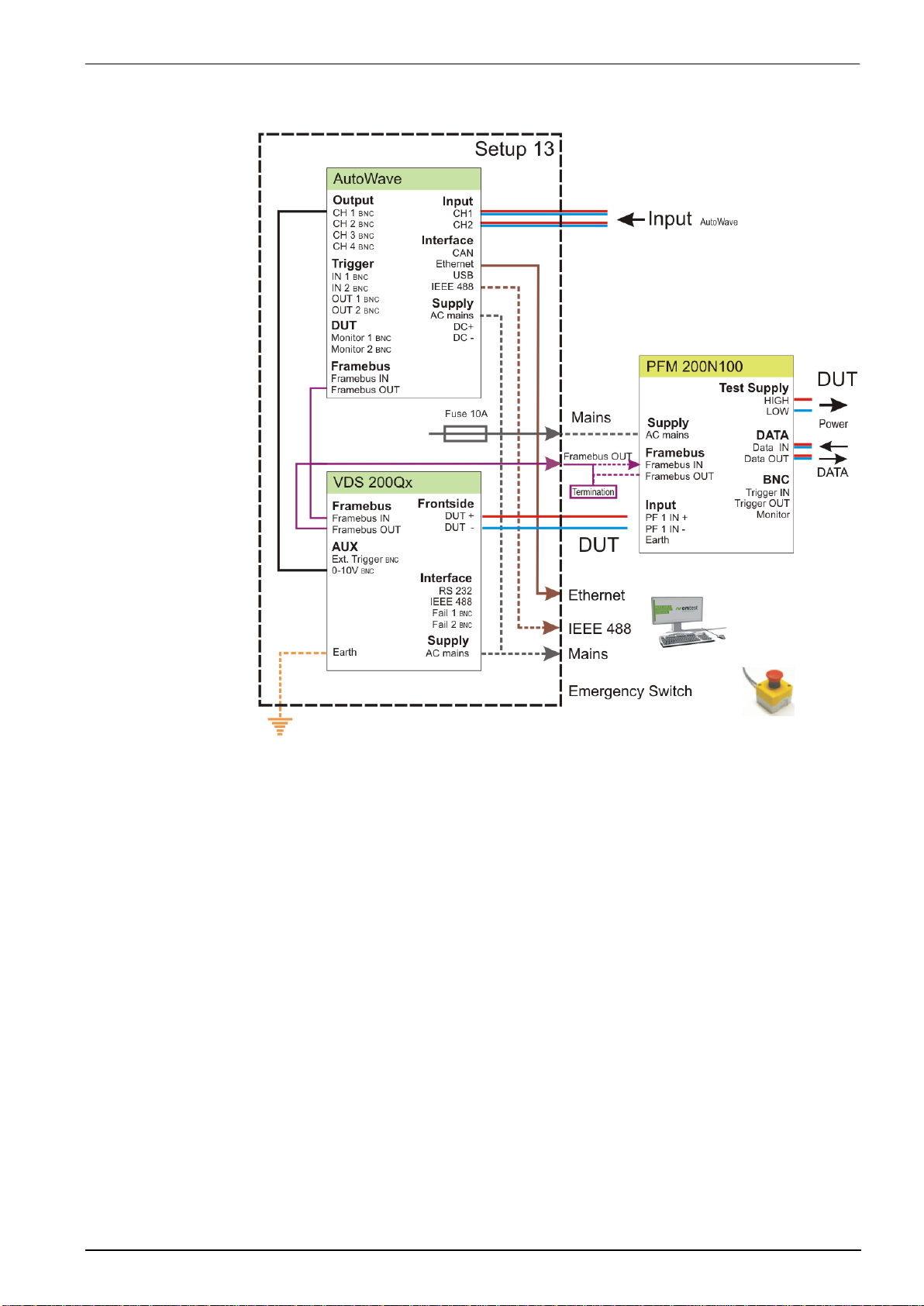
2.3.3.5.
Setup 13:
example with:
Rack
AutoWave
VDS 200Q100
External :
PFM 200N100
Setup with AutoWave and VDS 200Q and PFM 200N100
Manual for Operation V 5.9.1 23 / 45

EM TEST AutoWave
3.
3.1.
After switching on, AutoWave needs approx. 35s for booting. During this
time the display is blank. AutoWave is ready when the display shows
AutoWave and the current version.
The AutoWave is operated by an easy menu control system. Five
function keys are available to select parameters and functions.
3.2.
MODE button : Navigate through the menu WaveGenerator, WaveRecorder and Wave
Manager.
SETUP button : Configuration of the device settings
STOP button : Return to welcome screen ( Startup)
3.2.1.
1st line : Menu or submenu title
2nd line : Actual Menu Function
Operation
Power on
Menu structure
There are two buttons to navigate through the menus.
Mode Menu
Figure 4.1 shows the handling of the Mode menu which rotates cyclic by pressing the Mode button.
WaveGenerator
Easy waveform generation of all automotive standards.
Generation of all kind of voltage profiles via software.
Replay of waveforms from imported data or plot files.
Check of the DUT under real world conditions.
WaveRecorder
Recording the voltage variation in the lab setup.
Replay of the measured data via an adequate dc source or amplifier.
Check of the DUT under real world conditions.
Wave Manager
File exchange to/ from a memory stick for data transfer to an external computer.
Deleteing of waveforms
Figure 4.1 Mode Menu
Manual for Operation V 5.9.1 24 / 45

EM TEST AutoWave
3.2.1.1.
The output active LED indicates the output channel(s) of the selected
file.
Note : Files with multiple waves indicates all used output channels. The
software AutoWave delivers the detailed information about the
wave on each channel.
Select a file
1. Select with the buttons the desired file.
2. Press buttons to play and stop the file.
Start, Break and Continue
Functions
- Selecting files
- Play files
status blinking : Running
off : Ready to start
A selected wave will be repeated according to the selected number of “Events”. The time counter begins after
each restart at zero.
Key functions
Menu Wave Generator
Manual for Operation V 5.9.1 25 / 45

EM TEST AutoWave
Start, Break and Restart same file
Start, Stop and
return to WaveGenerator menu
Manual for Operation V 5.9.1 26 / 45

EM TEST AutoWave
3.2.1.2.
Channel selection
Recording
Functions
Recording the voltage variation in the lab setup.
Replay of the measured data via an adequate dc source or amplifier.
Check of the DUT under real world conditions.
Menu Wave Recorder
Manual for Operation V 5.9.1 27 / 45

EM TEST AutoWave
3.2.1.3.
Function selection
Select a file and
- Delete
- Copy
- Load
Functions
- Copy file to USB Memory stick
- Load file from USB Memory stick
- Delete file
Menu Wave Manager
Manual for Operation V 5.9.1 28 / 45

EM TEST AutoWave
3.2.2.
Setup Menu
In the setup menu all settings of the AutoWave can be done manually. The following figures show the
configuration of the different parameters.
How to navigate in the Setup menu
Figure 4.2 shows the handling of the Setup menu. The small buttons inside the circle shows how to step through
the menu or parameter list. The setup menu “Sample Frequency and Input Range“ occurs only when the option
record is built in.
Figure 4.2 Setup Menu
Manual for Operation V 5.9.1 29 / 45

EM TEST AutoWave
3.2.3.
Channel Selected output channel for setting the parameters
Source Source design for polarity output
Input U Max. input signal to control the power supply from
AutoWave ( individual each channel)
Output U Max. output signal of the power source to the DUT
Vset Manually setting DC output voltage of each channel.
(Vset ≤ Output)
Channel CH1, CH2, CH3, CH4
Source Unipolar , Bipolar
Input U Voltage range [ 0V ... 10.00V ] step 0.01
Output U Voltage range [ 0V...999.99V ] step 0.01
Examples for VDS
Unipolar
10.00V
30.00V or 60.00V
Toggle between the two edit modes with the button MODE
DC Source
Parameter to control the connected voltage source. This setting must be done for each channel CH1...CH4 with
a connected voltage source. AutoWave calculates automatically the correct output signal for controlling the
source.
Mode of value setting
The user has a choice of two modes to edit values for voltage and frequency parameters.
The “normal” mode is the usual one, and is done in two steps:
- first step to setup the integer part
- second step to setup the fractional part.
The “all step editor” mode selects each digit from left to right and the value is parsed sequentially.
“Normal” Mode
30.00VSETUP30.00V SETUPnext value to setup
Available keys:
STOP: Ends the editing, discarding any changes
LEFT: Decrease the value with acceleration
RIGHT: Increase the value with acceleration
SETUP: Move from integer part to fractional part and then validate the setting
MODE: Change editing mode to “All Step Edition”
Note: In this mode, when you are setting the integer part, the fractional is set to zero.
“All Step Editor” Mode
30.00VSETUP30.00V SETUP 30.00VSETUP30.00VSETUPnext value to setup
Available keys:
STOP: Ends the editing, discarding any changes
LEFT: Decrease the value with acceleration
RIGHT: Increase the value with acceleration
SETUP: Move the edited digit step by step from the left to right position / validate the setting
MODE: Change editing mode to “Normal”
Note: in this mode, any acceleration on LEFT or RIGHT key is disabled.
Manual for Operation V 5.9.1 30 / 45

EM TEST AutoWave
3.2.4.
Sampling frequency
Default 5kS/s
Sampling Frequency [kHz] depends on the number of channels
Single channel Dual channel
CH1 or CH2 CH1 and CH2
500kHz - 250kHz - 100kHz 100kHz
50kHz 50kHz
25kHz 25kHz
10kHz 10kHz
5kHz 5kHz
2.5kHz 2.5kHz
1kHz 1kHz
500Hz 500Hz
250Hz 250Hz
100Hz 100Hz
50Hz 50Hz
25Hz 25Hz
10Hz 10Hz
5Hz 5Hz
3.2.5.
Input Range bipolar input. Each channel can be set individually.
Channels : CH 1, CH2
Default : 100V
Ranges for both channels
5V
10V
20V
50V
100V
3.2.6.
Enable: Function of Trigger IN is enabled.
- Trigger IN 1, IN 2
Default : Enabled
Disable: Function of Trigger IN is disabled.
- Trigger IN 1, IN 2
Sample frequency (only with the option record)
Sample frequency for data recording. The max. sampling frequency is limited by the number of used measuring
channels.
Input Range (only with the option record)
Setting the measuring input range of the two input channels
Trigger
Setting of the trigger status
Manual for Operation V 5.9.1 31 / 45

EM TEST AutoWave
3.2.7.
The DUT Monitor 1 and DUT Monitor 2 control the behavior during a
test or record. The following settings are offered for the two DUT monitor
inputs
Default : Disabled
Settings DUT Monitor ( open collector input)
- Disable: Input has no function
- Notify: Message will be written on a file
- Stop: Wave stops and continue according the user decision
3.2.8.
Standard : IEEE 488
Address : 1...30
Default : 18 Default address for iso.control software
3.2.9.
Selectable range : 0.0.0.0 to 255.255.255.255
Default Address : 10.0.0.2
3.2.10.
Selectable range : 0.0.0.0 to 255.255.255.255
Default Netmask : 255.0.0.0
3.2.11.
Selectable range : 0.0.0.0 to 255.255.255.255
Default Gateway : 10.0.0.1
DUT Monitor
Open collector input for event control during a test or record.
GPIB Address
GPIB Address for using the AutoWave with the software iso.control
Ethernet IP- Address
Set Ethernet IP Address of the target AutoWave
Set Ethernet Netmask of the target AutoWave
Ethernet Netmask
Set Ethernet Gateway of the target AutoWave
Manual for Operation V 5.9.1 32 / 45
Ethernet Gateway

EM TEST AutoWave
3.2.12.
Day : 1...31
Month : 1...12
Year : 2000...2200
Note: When pressing Setup to exit the Date setup, the display returns after
few seconds delay to the Configuration display
3.2.13.
Format : HH.MM:SS ( H : Hour M : Minute S :Second )
Mode : 24 hours / day
Note: When pressing Setup to exit the Time setup, the display returns
after few seconds delay to the Configuration display
3.2.14.
3.2.15.
English : Default setting
German : Change to German language
The time is used for mark the stored files.
Date
Time
The LCD Contrast is selectable between the value 70 to 100.
Selection of the desired language.
LCD Contrast
Language
Manual for Operation V 5.9.1 33 / 45

EM TEST AutoWave
4.
Test Equipment
PC 104 Computer
The computer is a PC 104 board with AMD SC520 processor and 32 MB SDRAM
DSP Board
The DSP board is based on the DSP 56303 100 MHz from Motorola which includes two output channels with a
resolution of 16 bits / 500kHz
Extension Board
The extension board is a mezzanine card that includes:
- 2 input channels 16 bits / 500kHz
- 2 output channels 16 bits / 500kHz
Power supply
The AutoWave can be operated on two different power supply system.
- AC mains power
- DC supply from car battery
AC input
The AC mains power input is a wide range AC input that allows to operate the AutoWave in every country of the
world. With the voltage input range from 90V ... 250V and 47Hz ... 63Hz it is not necessary to use an adapter
transformer.
DC Input
The DC input is used for mobile operation in a car. The input is designed for 12V and 24V systems
Internal Battery (optional)
An internal battery pack is used for buffer voltage dips. In case of dropouts below approx. 3V, the device will
switch off and reboot when the DC voltage is higher than 10V. The Autowave does not operate with the
internal buffer battery.
Manual for Operation V 5.9.1 34 / 45

EM TEST AutoWave
5.
AutoWave
Number of output channels
2 channels;
2 additional channels can be added as an option (ExtBoard)
Output voltage
10V, unipolar or bipolar
Resolution
16 Bit
Frequency range
DC ... 50kHz ( 10samples per sinus period at 500kSample/sec )
Output Range
10V
Output Type
Single Ended
Resolution
16 bit
Differential linearity error
8 LSB (DAC)
Integral linearity error
4 LSB (DAC)
Accuracy
(0.5% + 5mV)
Maximum Sampling Rate
500kS/s (Accuracy: 50ppm) for one channel
Transition Time
< 5s Tested with 1kHz Square wave (20Vpp / without Offset).
Output Impedance
50
Max Output Current
10mA Output short circuit protected.
Wave Forms
Segment types
DC voltage
Sine
Sine sweep ( log, linear )
Damp Sine
Sine Ramp
Square wave
Profile
Triangular
Sawtooth
Ramp up / Ramp down
Step
Exponential
Calculated based on mathematical formula
Segment duration
Unlimited
Segments per wave form
20-30 depends on the complexity of the segment
WaveRecorder
Number of input channels
2 channels (ExtBoard for AutoWave required)
Input voltage ranges
5V, 10V, 20V, 50V and 100V;
unipolar or bipolar
Resolution
16 Bit
Accuracy
better than 0.2%
Frequency range
DC ... 50kHz
Sampling rate (selectable)
5S/s...500kS/s (one channel)
5S/s...100kS/s (two or four channels)
Storage
File size max. 1 GByte
Technical data
Manual for Operation V 5.9.1 35 / 45

EM TEST AutoWave
Display and Controls
Display
Text LCD 2 lines, 40 characters
LED indicators
Power On
Active channel 6 (2 inputs, 4 outputs)
Trigger
Running status
Operation
6 function keys
Trigger and DUT Monitoring
Trigger
2 inputs, 2 outputs
DUT monitoring
2 inputs, configurable
Control
Computer
PC 104 computer
AMD Microprocessor 100MHz
32MB RAM
Operating system
Linux, with Real time extension
DSP Signal processor
Motorola DSP 56303
Data storage
Hard disk 40GB ( standard )
Interfaces
GPIB Address 1...30
Ethernet
USB (for memory stick and ext. hard disc) I max. 500mA
CAN bus (for trigger)
Frame bus (internal system bus)
Storage battery
Lithium battery
Type: CR2032 3V, 235mAh 20.0 x 3.2 mm
Buffer battery ( option )
Rechargeable battery 12V, 2000mAh NiMH
Environmental Hard disk
Temperature
operating
5...40°C
storage
-20...60°C
gradient
20°C / hour
Humidity
10%...90% non-condensing
Vibration
Operating
1.0G
Non Operating
5.0G
Shock
Operating
225G ( 2ms)
Non Operating
900G ( 1ms)
General Data
Safety design
per IEC 1010, EN 61010
Power supply
AC: 90V ... 250V , 47Hz...63Hz
DC: 12V ... 32V, filtered and buffered
Fuses
F1 : 3.15 A slow blow ( DC )
F2 : 1.00 A slow blow ( AC )
Power requirement
40W max.
Dimension (W x H x D)
380 x100 x 390 mm
Weight
6kg
= => not relevant data for the standards can be changed by the manufacturer <= =
Manual for Operation V 5.9.1 36 / 45

EM TEST AutoWave
6.
6.1.
6.2.
6.2.1.
The EM Test equipment are calibrated in the factory and marked with a calibration
mark. The used measuring instruments are traceable to the Swiss Federal Office of
Metrology.
The calibration date is marked. The validity of the calibration is to the responsibility
of the user’s quality system. Neither the certificate of calibration nor the
corresponding label mark any due date for re-calibration.
Example: Calibration mark
6.2.2.
6.2.3.
6.2.4.
Maintenance
General
The AutoWave is absolutely maintenance-free.
Replacement of storage battery
Lithium battery : after approx. 10 years (indicates by memory lost of setting)
Internal battery pack (option) : NiMH type (Replace after .3..6 years necessary)
Calibration and Verification
Factory calibration
Every EM TEST generator is entirely checked and calibrated as per international standard regulations before
delivery. A calibration certificate is issued and delivered along with a list of the equipment used for the
calibration proving the traceability of the measuring equipment. All auxiliary equipment and accessories are
checked to our internal manufacturer guidelines.
The calibration certificate and the certificate of compliance (if available) show the date of calibration.
Guideline to determine the calibration period of EM Test instrumentation
Our International Service Departments and our QA Manager are frequently asked about the calibration interval
of EM TEST equipment.
EM TEST doesn’t know each customer’s Quality Assurance Policy nor do we know how often the equipment is
used and what kind of tests are performed during the life cycle of a test equipment. Only the customer knows all
the details and therefore the customer needs to specify the calibration interval for his test equipment.
In reply to all these questions we like to approach this issue as follows :
EM TEST make use of a solid state semiconductor switch technique to generate high voltage transients. A
precious advantage of this technique is the absolute lack of periodical maintenance effort. In consequence
thereof a useful calibration period has to be defined based on two criteria :
- The first one is the customer’s Quality Assurance Policy. Any existent internal regulation has to be applied at
highest priority. In the absence of such internal regulation the utilization rate of the test equipment has to be
taken into consideration.
- Based on the experience and observation collected over the years EM TEST recommend a calibration
interval of 1 year for frequently used equipment. A 2-years calibration interval is considered sufficient for
rarely used test generators in order to assure proper performance and compliance to the standard
specifications.
Calibration of Accessories made by passive components only:
Passive components do not change their technical specification during storage. Consequently the measured
values and the plots stay valid throughout the storage time. The date of shipment shall be considered as the
date of calibration.
Periodically In-house verification
Please refer to the corresponding standard before carrying out a calibration or verification. The standard
describes the procedure, the tolerances and the necessary auxiliary means. Suitable calibration adapters are
needed. To compare the verification results, EM Test suggests to refer to the waveshape and values of the
original calibration certificate.
Manual for Operation V 5.9.1 37 / 45

EM TEST AutoWave
6.3.
6.4.
7.
7.1.
7.2.
7.2.1.
Extension Board
- 2 output channels 16 Bit CH3 , CH 4 10V
- 2 input channels 16 Bit 100V
Calibration
For periodical calibration the AutoWave has to return back to the manufacturer
Verification
A verification can be done with the following procedure:
Output channel
Setting a defined voltage to the output channel and verification with a DMM ( 5½ digit )
Measuring: 0.00V
5.00V
10.00V
Delivery Groups
Basic equipment
Arbitrary generator type AutoWave
Mains cable
Calibration certificate
Manual on USB memory stick
Safety manual
Accessories and options
Extension Board
Manual for Operation V 5.9.1 38 / 45

EM TEST AutoWave
7.3.
7.3.1.
Product Features:
• True 10/100Mbps Network Connectivity
• Auto 10/100Mbps Speed Detection
• Backwards Compatible with USB 1.1
Useful Accessories
The Accessories in this paragraph are not part of the EM Test delivery list. EM Test suggest to buy this
devices from a local dealer.
Hi-Speed USB 2.0 Fast Ethernet Adapter installation
For user where no Ethernet connector is available, EM Test suggest to buy an USB - Ethernet adapter on the
IT-market. This USB – Ethernet adapter is not part of the EM Test delivery.
EM Test proposes and tested the following device:
D-Link : DUB-E100
For communication with the AutoWave via Ethernet a Hi-Speed USB 2.0 Fast Ethernet Adapter type DUB-E100
is available. This connection is used if the AutoWave is not installed in a rack with other EM Test equipment.
Product Description:
The D-Link DUB-E100 is a Hi-Speed USB 2.0 10/100Mbps Fast Ethernet Adapter specifically designed to plug
into an available Universal Serial Bus (USB) port on a desktop or laptop PC under Microsoft Windows XP, Me,
2000 or 98SE. Based on USB 2.0, the DUB-E100 extends the transfer speed of earlier USB Fast Ethernet
adapters to true 10/100Mbps connectivity.
As a USB device, the D-Link DUB-E100 eliminates the need to use an ISA, PCI, or PC Card slot to add LAN
connectivity to a PC desktop or laptop computer. Installation and use are further simplified by living the USB's
out-of-the-box installation approach to connecting computer peripherals. You will not need to open the case of
your computer, nor will you be required to set IRQ's. The D-Link DUB-E100 represents the simplest way to
connect your computer to an Ethernet based network.
The D-Link DUB-E100 provides a standard RJ-45 connector for a quick and simple method of connecting to an
Ethernet 10Mbps or Fast Ethernet 100Mbps based LAN via a network hub or switch. The built-in USB 2.0 cable
connects directly to your computer or laptop.
Power for the DUB-E100 is provided directly by the USB bus, eliminating the need for an external power
adapter. It also supports USB's energy saving suspension and resumes functions to minimize power
consumption, which is specifically useful for laptop/notebook users.
Manual for Operation V 5.9.1 39 / 45

EM TEST AutoWave
8.
8.1.
A : After the installation or update of the
AutoWaveControl software.
A message box may automatically appear if
AutoWaveControl software detects an older
firmware on the AutoWave.
1. Press the OK button to enter the Device
update window.
B : When the user has different firmware
versions to operate with the AutoWave.
1. Press the Update button in the device
setup for enter the Device update window.
Actual Firmware Version field :
Firmware version being installed in the
AutoWave.
Select the Firmware field :
Firmware versions in the computer for
download into the AutoWave.
2. Press the Download button to download
the new firmware into the AutoWave.
Annex
Update a new Firmware
To update the Firmware start the program AutoWaveControl. A firmware update is recommended :
Manual for Operation V 5.9.1 40 / 45

EM TEST AutoWave
After “download the AutoWave display shows
AutoWave REMOTE
AuitoWave.tgz stored
The message “File Stored” confirms the
successful download of the new firmware to
AutoWave.
3. Press the Reboot button for Booting the
AutoWave.
During the booting process the AutoWave
will install the new firmware version
A bar graph shows the booting progress.
After a successful update the actual firmware
of the AutoWave is displayed in the field
“Actual Firmware Version”.
4. Press the OK button to return to the
Device Setup Window.
Manual for Operation V 5.9.1 41 / 45

EM TEST AutoWave
8.2.
Segment name
Picture
Description
DC
Constant DC voltage at V1 level during the selected
duration t1.
Ramp
Voltage ramp where the time t1 goes from 0% to 100% or
10% to 90%
Square
Square function with defined voltage parameters V1 and V2
offset and the square duration of V1 and V2.
Triangle
sawtooth
Step
Sine
Sine Sweep
Sine wave with frequency sweep over the duration t1. The
sine starts with the frequency f1 and ends with the
frequency f2. The frequency can sweep up or down with the
frequency.
Sine ramp
Switching
Damped sine
Description:
Damped sine with asymptote end voltage on Vp2 offset
level = V1-Vp1
Exponent
Description:
This function simulates a fall or rise of an exponential
impulse waveshape. It simulates a typical fall or rise of a
capacitive impulse waveshape.
Basic Waves
The AutoWave generates the waves like an arbitrary generator as PointWaves, where all samples are stored in
a file. As an advantage the AutoWave firmware generates the waves as segmented waves from a parameter
list. This has the advantage to save a lot of memory and to create waves who can not be realized by
PointWaves.
The following waves are programmed inside the AutoWave:
Manual for Operation V 5.9.1 42 / 45

EM TEST AutoWave
Profile
Square Ramp
Manual for Operation V 5.9.1 43 / 45

EM TEST AutoWave
8.3.
Manufacturer :
EM TEST Switzerland GmbH
Address:
Sternenhofstr. 15
CH 4153 Reinach
Switzerland
Product‘s name:
AutoWave
EN 61010-1 : 2011
Safety requirements for electrical equipment for measurement, control, and
laboratory use.
EN 61326-1 : 2013
Electrical equipment for measurement, control and laboratory use Class A
EN 61000-3-2 : 2014
Limits for harmonic current emissions
EN 61000-3-3 : 2013
Limitation of voltage changes, voltage fluctuations and flicker in public lowvoltage supply systems.
European representative
Manufacturer
AMETEK CTS Germany GmbH
EM TEST (Switzerland) GmbH
Lünenerstr. 211
Sternenhofstr. 15
D 59174 Kamen
CH 4153 Reinach
Tel: +49 (0) 2307 / 26070-0
Tel: +41 61-7179191
Fax: +49 (0)2307 / 17050
Fax: +41 61-7179199
By
N. Holub
General manager
A. Burger
Design and Research
Place
Kamen, Germany
Reinach BL , Switzerland
Date
25. February 2016
25. February 2016
Declaration of CE-Conformity
declares, that under is sole responsibility, the product’s listed below, including all their options, are conformity with
the applicable CE directives listed below using the relevant section of the following EC standards and other
normative documents.
Low Voltage Directive 2014/35/EU
Standard to which conformity is declared:
EMC Directive 2014/30/EU
Standard(s) to which conformity is declared:
Manual for Operation V 5.9.1 44 / 45

EM TEST AutoWave
8.4.
AutoWave - General Diagram
Manual for Operation V 5.9.1 45 / 45
 Loading...