

Page 1

ASSA ABLOY, the global leader in door opening solutions
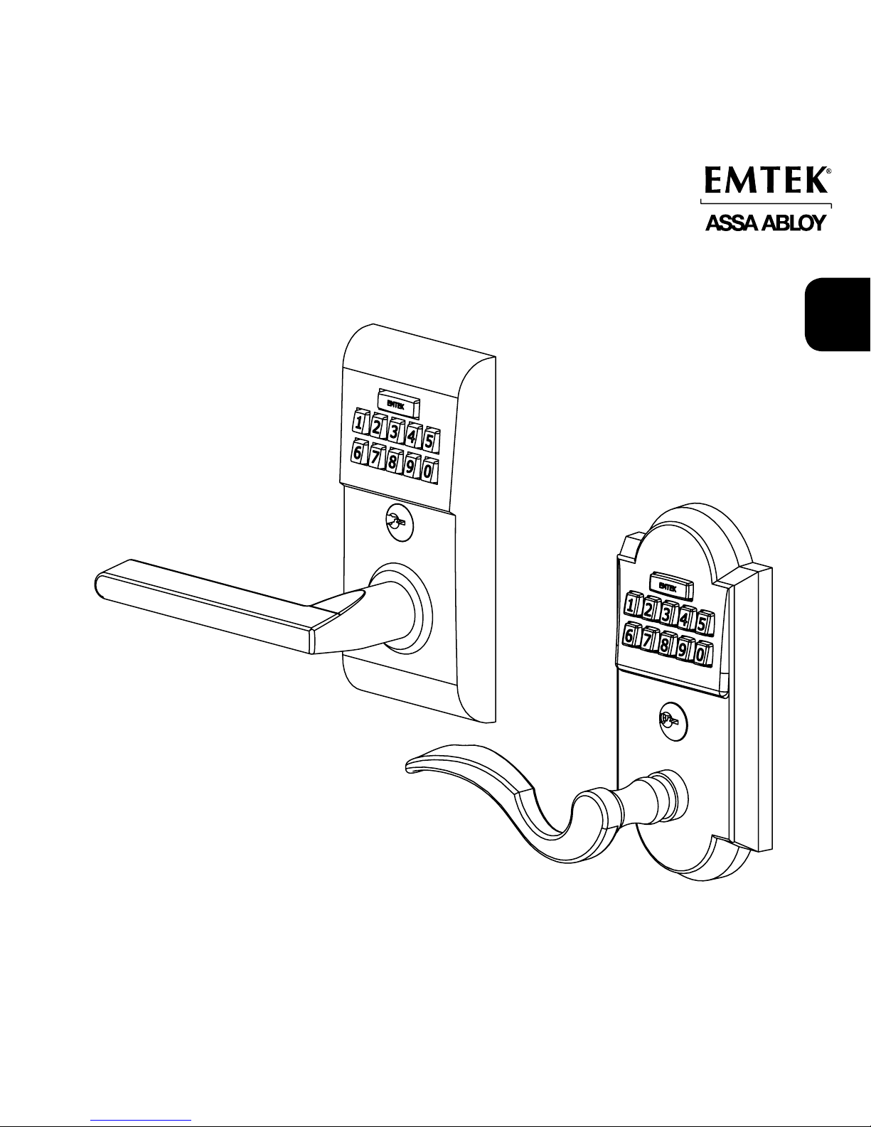
Installation & Programming Guide
Modern Style & Classic Style
Electronic Keypad Lever Locksets
Modern Style Keypad
Classic Style Keypad
Page 2
2
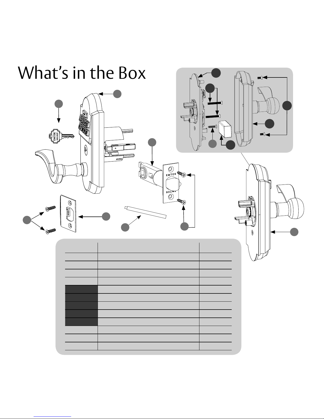
ITEM NO. DESCRIPTION QTY.
1 Key 2
2 Outside Trim Plate Assembly 1
3 Latch for 2⁄” or 2¾” Backset 1
4 Inside Trim Plate Assembly 1
4a Inside Chassis 1
4b Inside Trim Plate 1
4c #8-32 x ⁄" Flat Head Machine Screw 2
4d 9V Alkaline Battery 1
5 #8-32 x 1½" Flat Head Machine Screw 2
6 #8 x ¾" Wood Screw 5
7 Strike Plate 1
8 Plastic Extender 1
8
7
3
1
2
6
6
4
4b
4a
4c
4d
5
6
What’s in the Box
Page 3

3
EN
Confirm Handing
HANDING OF DOOR IS ALWAYS DETERMINED FROM THE OUTSIDE
Hinge is on the left.
Door is Left Hand (LH)
Hinge is on the right.
Door is Right Hand (RH)
Hinge is on the right.
Door is Right Hand (RH)
Hinge is on the left.
Door is Left Hand (LH)
In-Swing Doors Out-Swing Doors
outsideoutside
Preparation
Fasten Strike Plate using
two #8 x ¾” Wood Screws
(item #6).
A
2 ⁄” or 2 ¾”
Backset
2 ⁄” Dia
Bore
⁄” Deep
2 ¼”
1 “
1” Diameter
Edge Bore
Door Prep
B D
Door Jamb Prep
1” Deep,
1” Diameter
Edge Bore
⁄” Deep
1-1/8"
2-3/4"
C
2 ¼”
1 ½”
Install Strike Plate
Page 4

4
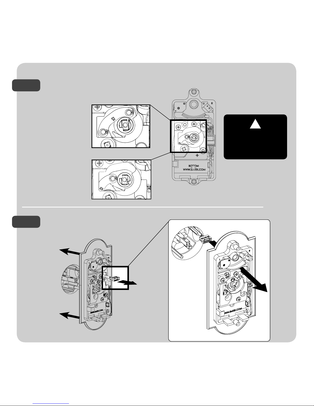
Use a Phillips head screwdriver to remove
screws (item #4c) shown below and detach
Inside Trim Plate from the Inside Chassis.
Fasten Latch using two
#8 x ¾” Wood Screws
(item #6).
Remove Screws from Inside Trim Plate
How to Install
!
Remove inside chassis from
trim plate before installing
the outside trim. Thumbturn
must be in neutral position.
Install Latch
LH RH
See Page 3 for Handing
Information.
1
2
Page 5

EN
5
Install Outside Trim Plate Assembly
While holding Outside Trim
Plate Assembly, Press the Plastic
Extender (A) into end of Spindle
Shaft (B). The Shaft is properly
aligned when the marking
‘TOP’ can be seen from
an overhead view.
Position the Outside Trim Plate Assembly through the bore hole.
With the Outside Trim Plate Assembly ush to the door, REMOVE the Plastic Extender.
Feed wire harness
through the bore hole.
B
!
A
Fit Plastic Extender
through latch.
Once positioned,
outside trim plate
assembly requires
support.
This side
on top.
!
3
STEP 2
STEP 3
STEP 1
Page 6
6
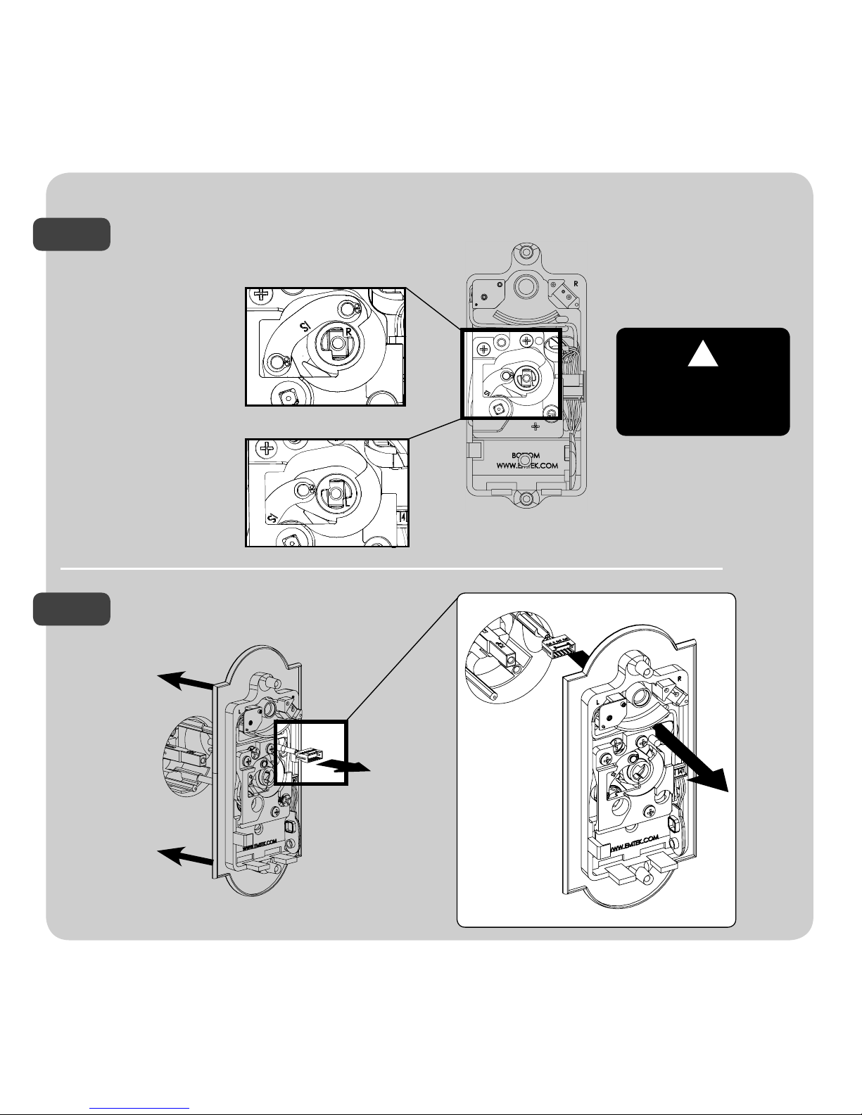
Install Inside Chassis
Cam link must remain
in the correct position
during installation.
!
Conrm the position of Cam Link.
For Left Hand Locks:
Turn to left position.
For Right Hand Locks:
Turn to right position.
Feed the Wire Harness through Inside Chassis.
4
STEP 1
STEP 2
Page 7

7
EN
Check alignment before
fully tightening screws.
!
Connect Wire Harness (A) and tuck Connectors as shown (B).
A B
Install Battery.
For optimal performance, always
use a good quality battery.
Optional - An additional #8
wood screw (provided) can
be installed to prevent the
interior trim from rotating
9V Battery
Fasten Inside Chassis using two #8-32 x 1½”
Flat Head Machine Screw (item #5).
STEP 3
STEP 4
STEP 5
Page 8

8
Screws (item #4c)
*Neutral position is required for installation and removal of the Inside Trim Plate Assembly.
!
Inside
Correct position for installation.
Thumbcam must be positioned
as shown (Neutral Position)*
!
5
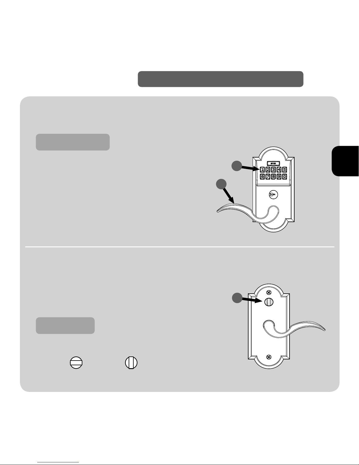
User codes are located
on the inside trim plate
& back cover page.
Fasten Inside Trim Plate using two#8-32 x ⁄”
Flat Head Machine Screws (item #4c).
Install Inside Trim Plate
Page 9

9
EN
Your Emtek lock is shipped with two 4-digit user codes and a 6-digit programming code.
These codes are randomly generated at the factory.
(Turn to next page for Programming Instructions.)
To Unlock
1. Enter 4-digit user codes.
(See sticker located on the inside
trim plate or back cover page).
2. Turn Handle.
To Lock
1. Rotate Thumbturn from inside.
Passage Feature
(Does not apply to Keypad Storeroom/Gate product)
Activate by turning the inside thumbturn to the unlocked
position. This will engage the outside lever so a code is not
required to enter.
Your Lock is Ready to Use
How to Use
Locked Unlocked
1
1
2
Page 10
In order to perform each of the following six functions, the lock must rst be placed in Programming Mode:
*If no input within 10 seconds, Yellow LED goes out, Red LED ashes and lock exits Programming Mode.
1. Press and hold EMTEK button for 3 seconds
2. Yellow LED ashes, then remains solid*
3. Enter Programming Code
4. Green LED ashes, then 2 beeps
5. Yellow LED remains solid
(awaiting button press; see following table)
If You Wish To Press Button Actions Indicators
Change
Programming Code
(6 digits)
1
Enter New
Programming
Code
(6 digits)
Re-Enter New
Programming
Code
(6 digits)
• 1 Green LED ash
• 1 beep
• 1 Green LED ash
• 1 beep
• 2 Green LED ashes
• 2 beeps
Add User Code
(4 digits)
(Store up to 20 User Codes)
2
Enter New User
Code
(4 digits)
Re-Enter New
User Code
(4 digits)
• 1 Green LED ash
• 1 beep
• 1 Green LED ash
• 1 beep
• 2 Green LED ashes
• 2 beeps
Delete User Code 3
Enter User Code
to be Deleted
Re-Enter User
Code to be
Deleted
• 1 Green LED ash
• 1 beep
• 1 Green LED ash
• 1 beep
• 2 Green LED ashes
• 2 beeps
**Enable/Disable All User Codes 4
Entering ‘4’ disables all Users
(enables all if disabled)
• 2 Green LED ashes
• 2 beeps
Delete All User Codes 5
Re-Enter Programming Code
• 1 Green LED ash
• 1 beep
• 2 Green LED ashes
• 2 beeps
Turn Beeper On/O 6
Entering ‘6’ turns OFF (or ON)
• 1 Green LED ash
• 1 beep
• 2 Green LED ashes
• 2 beeps
**Also referred to as “vacation mode”. This command temporarily disables all user codes (metal key override will still work).
How to Program
Programming Your Lock
Page 11

Function Indicators
Valid Code
• 1 short beep, EMTEK button ashes Green.
Invalid Code/Access Denied*
• 1 Red LED ash
• 2 short beeps
Lock-Out Mode Error
• 2 short beeps
• 1 short beep per second for duration
Access Accepted
• 1 short beep
• 1 Green LED ash
Low Battery
• 4 Red LED ashes
• 4 short beeps
Blackout Battery
**
• 1 long Red LED ash
• 4 long beeps
Button Press Accepted
• 1 Yellow LED ash
• 1 Short Beep
Outside Thumb Turn Enabled
• 2 Green LED ashes
• Remove power (disconnect 9V battery) from Lock.
• Press and hold EMTEK button.
• While continuing to hold EMTEK button, restore power
(reconnect 9V battery).
• Continue to hold EMTEK button for 3 seconds.
• 1 Green LED ash and 2 short beeps followed by 1 Green LED Flash and
2 short beeps indicates the lock has been successfully restored
Restoring the Lock to Factory Default Setting
This procedure clears the lock of all users and restores the Programming Code and 2 User Codes
shipped with the lock.
11
EN
* If 3 consecutive incorrect codes are entered, the lock emits 4 short beeps and a ashing Red EMTEK button. The lock will not
accept additional input for 20 seconds (20 beeps). When the next valid code is entered the lock will beep quickly 3 times to alert
of the incorrect codes.
**
Battery voltage has dropped too low; keypad will be disabled but metal key override will still work.
Keypad Operation - Beeper & LED Indicators
U.S. patents:
8,176,761
8,141,400
Canadian patents:
2,698,041
2,789,278
2,789,280
Page 12

12
Page 13
13
ASSA ABLOY, the global leader in door opening solutions
Guide d’installation et de programmation
FR
Levier et clavier électroniques pour jeu de serrures
Style Moderne et Style Classique
Clavier Style Moderne
Clavier Style Classique
Page 14

14
ARTICLE N° DESCRIPTION QTÉ
1 Clé 2
2 Assemblage de la plaque de garniture extérieure 1
3 Loquet pour 2⁄ po ou 2 ¾po appuie-tête 1
4 Assemblage de la plaque de garniture intérieure 1
4a Bâti intérieur 1
4b Plaque de garniture intérieure 1
4c Vis à métal à tête plate #8-32 x ⁄ po 2
4d Pile alcaline de 9 V 1
5 Vis à métal à tête plate #8-32 x 1½po 2
6 Vis à bois #8 x ¾po 5
7 Plaque de gâche 1
8 Rallonge en plastique 1
8
7
3
1
2
6
6
4
4b
4a
4c
4d
5
6
Que contient la boîte
Page 15

Écartement
de 2 ⁄ po
ou 2 ¾ po
Diamètre
interne
de 2 ⁄
po
Profondeur
de ⁄ po
2 ¼ po
1 po
Trou de perçage
de 1 po de
diamètre
Préparation de la porte
B
Préparation de
l’embrasure de porte
C
Profondeur de
1 po, Trou de
perçage de
1 po de
diamètre
⁄ po de
Profondeur
1-1/8"
2-3/4"
2 ¼po
1 ½po
Fixez la plaque de gâche à l’aide
des deux vis à bois n° 8 x ¾ po
(article n° 6).
Installation de
la plaque de gâche
D
15
FR
Confirmation du sens d’ouverture
LE SENS DE LA PORTE EST TOUJOURS DÉTERMINÉ DE L’EXTÉRIEUR
Extérieur
Extérieur
Préparation
A
Charnière sur la gauche –
porte avec ouverture vers
la gauche (MG)
Charnière sur la gauche –
porte avec ouverture vers
la gauche (MG)
Charnière sur la droite – Porte
avec ouverture vers la droite
(MD)
Charnière sur la droite – Porte
avec ouverture vers la droite
(MD)
Portes avec ouverture vers l’intérieur. Portes avec ouverture vers l’extérieur
Page 16

16
À l’aide d’un tournevis Phillips, retirez les vis (article
n° 4c) illustrées ci-dessous et détachez la plaque de
garniture intérieure de l’intérieur du bâti.
Fixez le pêne à l’aide des
deux vis à bois n° 8 x ¾po
(article n° 6).
Retirez les vis de la plaque de garniture intérieure
Pour installer
!
Avant d’installer la garniture extérieure,
retirez le bâti intérieur de la plaque de
garniture. La barette tournante doit
être dans la position neutre.
Installation du pêne
LH RH
Voir page 15 pour du sens
d’informations.
1
2
Vis
(article no° 4c)
Page 17

17
FR
Installation de l’assemblage de la plaque de garniture extérieure
Tout en maintenant l’assemblage de
la plaque de garniture extérieure,
appuyer sur la rallonge en plastique
(A) pour l’insérer dans l’arbre
de broche (B). L’arbre est aligné
correctement lorsque la
marque ”TOP” peut être
vue du dessus.
Positionnez l’assemblage de la plaque de garniture extérieure dans le trou de la poignée.
Alors que l’assemblage de la plaque de garniture est aligné sur la porte, RETIREZ
la rallonge en plastique.
B
A
3
ÉTAPE 2
ÉTAPE 3
ÉTAPE 1
Ce côté vers
le haut.
!
Faites passer le faisceau
de câblage par le trou de
la poignée.
Fixez la rallonge en
plastique dans le pêne.
!
Une fois en place,
l’assemblage de la
plaque de garniture
extérieure nécessite du
soutien.
Page 18

18
Installation du bâti intérieur
Conrmation du lien de la came.
Pour les serrures avec
ouverture à gauche:
Tournez vers la position
de gauche.
Pour les serrures avec
ouverture à droite :
Tournez vers la position
de droite.
Faites passer le faisceau de câblage dans
le bâti intérieur.
4
ÉTAPE 1
ÉTAPE 2
Le lien de la came
doit demeurer dans
la position adéquate
durant l’installation.
!
Page 19

19
FR
Branchez le faisceau de câblage (A) dans les connecteurs horizontaux tel qu’illustré (B).
A B
Installez la pile.
Pour une performance
optimale, utilisez toujours une
pile de bonne qualité.
Fixez le bâti intérieur à l’aide de deux vis à métal
n° 8-32 x 1½ po à tête plate (article n° 5).
ÉTAPE 3
ÉTAPE 4
ÉTAPE 5
Pile de 9V
Avavccnt de fixer
fermement les vis,
vérifiez l’alignement.
!
En option - Une vis à bois #
8 supplémentaire (fournie)
peut être installée pour
empêcher la garniture
intérieure de tourner
Page 20

20
Vis (article n° 4c)
*Position neutre verrouillée est requise pour l’installation et pour retirer l’assemblage de la plaque de garniture intérieure.
Intérieur
5
Fixez la plaque de garniture intérieure à l’aide
de deux vis à métal n° 8-32 x ⁄ po à tête plate
(article n° 4c).
Installation de la plaque de garniture intérieure
!
Les codes d’utilisateurs
se trouvent sur la plaque
de garniture intérieure
et reportez-vous à la
couverture arrière.
Position adéquate pour
l’installation. La came de blocage
à oreilles doit être placée tel que
illustré (position neutre)*
!
Page 21

EXTÉRIEUR
21
FR
Lors de la livraison, votre serrure Emtek est congurée avec deux codes d’utilisateur à 4 chires
et un code de programmation à 6 chires. Ces codes sont générés au hasard à l’usine.
(Pour obtenir les instructions de programmation, reportez-vous à la page suivante.)
Pour déverrouiller
1. Entrez les codes d’utilisateurs à 4 chires.
(Voir l’étiquette située sur la plaque de garniture intérieure
ou reportez-vous à la couverture arrière).
2. Tournez la poignée.
Pour verrouiller
1. Tournez la poignée à barrette
tournante par l’intérieur.
Fonction pour passage
Ceci ne s’applique pas dans le cas d’un clavier d’entreposage/produits pour barrière de sécurité (gate)
Activez la fonction en tournant la poignée à barrette tournante à la
position déverrouillée. Ceci va engager le levier extérieur de façon à
ce qu’aucun code ne soit requis pour entrer.
Votre serrure est prête à être utilisée
Comment utiliser la serrure
INTÉRIEUR
1
1
2
Verrouillée Déverrouillée
Page 22

Si vous désirez
Appuyez sur
la touche
Actions Voyants
Modier le
code de
programmation
(6 chires)
1
Entrez le
nouveau code de
programmation
(6 chires)
Entrez une
deuxième fois le
nouveau code de
programmation
(6 chires)
• 1 clignotement de la DEL Verte
• 1 bip
• 1 clignotement de la DEL Verte
• 1 bip
• 2 clignotements de la DEL Verte
• 2 bips
Ajouter un code d’utilisateur
(4 chires)
(Jusqu’à 20 codes d’utilisateur
peuvent être stockés)
2
Entrez le
nouveau code
d’utilisateur
(4 chires)
Entrez une
deuxième fois le
nouveau code
d’utilisateur
(4 chires)
• 1 clignotement de la DEL Verte
• 1 bip
• 1 clignotement de la DEL Verte
• 1 bip
• 2 clignotements de la DEL Verte
• 2 bips
Supprimer un code
d’utilisateur
3
Entrez le code
d’utilisateur que
vous désirez
supprimer
Entrez une
deuxième fois le
code d’utilisateur
que vous désirez
supprimer
• 1 clignotement de la DEL Verte
• 1 bip
• 1 clignotement de la DEL Verte
• 1 bip
• 2 clignotements de la DEL Verte
• 2 bips
**Activer/Désactiver tous les
codes d’utilisateurs
4
Entrer “4” désactive tous les
utilisateurs (les active tous s’ils étaient
désactivés)
• 2 clignotements de la DEL Verte
• 2 bips
Supprimer tous les codes
d’utilisateur
5
Entrez de nouveau le code de
programmation
• 1 clignotement de la DEL Verte
• 1 bip
• 2 clignotements de la DEL Verte
• 2 bips
Mettre EN ou HORS service
l’avertisseur sonore
6
L’entrée de “6” le met HORS fonction
(EN fonction)
• 1 clignotement de la DEL Verte
• 1 bip
• 2 clignotements de la DEL Verte
• 2 bips
22
De façon à pouvoir eectuer chacune des six fonctions ci-dessous, la serrure doit d’abord être mise en mode de programmation :
1. Maintenez la touche EMTEK enfoncée durant 3 secondes
2. La DEL Jaune clignote et demeure ensuite allumée*
3. Entrez le code de programmation
4. La DEL Verte clignote et ensuite 2 bips se font entendre
5. Le DEL Jaune demeure allumée (attendant qu’une touche
soit enfoncée: voir le tableau ci-dessous
Pour faire la programmation
Programmation de votre serrure
*Si aucune entrée n’est effectuée durant 10 secondes, la DEL Jaune s’éteint, la DEL Rouge clignote et la serrure quitte le mode
de programmation
**Veuillez également vous reporter au “mode Vacances”. Cette commande désactive temporairement tous les codes
d’utilisateur (mais la clé métallique fonctionne toujours).
Page 23

Fonction Voyants
Code valide
• 1 bip court. La touche EMTEK clignote en Verte
Code invalide/Accès refusé*
• 1 clignotement de La DEL Rouge
• 2 bips courts
Erreur - Mode de verrouillage
• 2 bips courts
• 1 bip court toute les secondes pour toute la durée de l’opération
Accès permis
• 1 bip court
• 1 clignotement de la DEL Verte
Pile faible
• 4 clignotements de la DEL Rouge
• 4 bips courts
Pile défectueuse**
• 1 long clignotement de la DEL Rouge
• 4 bips longs
Touche enfoncée acceptée
• 1 clignotement de la DEL Jaune
• 1 bip court
Poignée à barrette tournante extérieure activée
• 2 clignotement de la DEL Verte
Rétablissement de la serrure à ses réglages par défaut
Cette procédure eace tous les utilisateurs de la serrure et rétablit le code de programmation et les deux
codes d’utilisateur à leur valeur par défaut congurée à l’usine.
* Si trois codes erronés consécutifs sont entrés, la serrure émet 4 bips courts et la touche EMTEK clignote enrouge. La serrure
n’acceptera pas de code additionnel durant 20 secondes (20 bips). Lorsqu’un prochain code valide est entré, la serrure émet 3 bips
rapides pour indiquer que des codes invalides ont été précédemment entrés.
** La tension de la pile a chuté trop bas: le clavier sera désactivé mais une clé métallique peut être utilisée pour déverrouiller la serrure.
• Enlevez l’alimentation (débranchez la pile de 9V) de la serrure
• Appuyez sur la touche EMTEK
• Tout en gardant la touche EMTEK enfoncée, rétablissez le courant
(rebranchez la pile de 9V)
• Continuez de maintenir la touche EMTEK enfoncée durant 3 secondes
• La DEL Verte clignote 1 fois, deux bips se font ensuite entendre et la DEL
Verte clignote deux fois rapidement; les bips indiquent que la serrure a
été correctement rétablie
23
FR
Fonctionnement du clavier - Avertisseur sonore et voyants à DEL
©
Emtek Products, inc., 2017. Une entreprise du groupe ASSA ABLOY. Tous droits réservés. La reproduction totale
ou partielle sans l’autorisation expresse écrite par Emtek Products, inc. est interdite.
Le brevet américain:
8,176,761
8,141,400
Canadian Brevets:
2,698,041
2,789,278
2,789,280
Page 24

Page 25

25
ASSA ABLOY, the global leader in door opening solutions
Guía de Instalación y Programación
ES
Estilo Moderno y Estilo Clásico
Palanca y Teclado Electrónico para Juego de
Cerraduras Teclado Estilo
Teclado Estilo Moderno
Teclado Estilo Clásico
Page 26

26
ARTÍCULO Nº DESCRIPCIÓN CANT.
1 Llave 2
2 Montaje de la Placa Decorativa externa 1
3 Pestillo para 2⁄” o 2 ¾” de Distancia 1
4 Montaje de la Placa Decorativa Interior 1
4a Chasis Interno 1
4b Placa Decorativa Interior 1
4c Tornillo de Cabeza Plana de #8-32 x ⁄” 2
4d Batería Alcalina de 9V 1
5 Tornillo de Cabeza Plana de #8-32 x 1 ½” 2
6 Tornillo para Madera de #8 x ¾” 5
7 Placa de Impacto 1
8 Extensor de Plástico 1
8
7
3
1
2
6
6
4
4b
4a
4c
4d
5
6
Qué Hay en la Caja
Page 27

B C D
27
Puertas que abren hacia adentro
Puertas que abren hacia afuera
afueraafuera
ES
2 ⁄” ó 2 ¾”
de Distancia
Diámetro
de Oricio
2 ⁄”
2 ¼”
1 “
Diámetro
Borde de
Oricio 1”
Preparación de la Puerta Preparación de la Jamba
Confirme el Manejo
LA OPERACIÓN DE LA PUERTA ESTÁ SIEMPRE DETERMINADA DESDE AFUERA
La bisagra está a la izquierda
La puerta es Izquierda (LH)
La bisagra está a la derecha
La puerta es Derecha (RH)
La bisagra está a la derecha
La puerta es Derecha (RH)
La bisagra está a la izquierda
La puerta es Izquierda (LH)
Profundidad
1”
Diámetro
Borde de
Oricio 1”
Profundidad
⁄”
1-1/8"
2-3/4"
Asegure la Placa de Impacto
usando dos Tornillos para
Madera #8 x ¾” (artículo #6).
Instale la Placa de Impacto
Preparación
Profundidad
⁄”
A
1 ½”
2 ¼”
Page 28

28
Use un destornillador Phillips para retirar los tornillos
(artículo #4c) mostrados abajo y separe la Placa
Decorativa Interior del Chasis Interno.
Asegure el Pestillo usando
dos Tornillos para Madera
#8 x ¾” (artículo #6).
Retire los Tornillos de la Placa Decorativa Interior
Cómo Instalar
!
Retire el chasis interno de la placa
decorativa antes de instalar la placa
exterior. El Cerrojo manual debe estar
en posición neutral.
Instale el Pestillo
LH RH
Ver Hoja 27 para Información
de manejo
1
2
Tornillos
(Artículo #4c)
Page 29

29
Instale el Montaje de la Placa Decorativa Exterior
Mientras sostiene el Montaje
de la Placa Decorativa Exterior,
Presione el Extensor de Plástico
(A) dentro del Eje del Rotor (B).
El Rotor está apropiadamente
alineado cuando la marca
‘TOP’ puede ser visualizada
desde arriba.
Posicione el Montaje de la Placa Decorativa Exterior a través del oricio.
Con el Montaje de la Placa Decorativa Exterior alineado a la puerta, RETIRE Extensor de Plástico.
B
A
3
PASO 2
PASO 3
PASO 1
!
Una vez que está
posicionado, el
montaje de la placa
decorativa exterior
requiere soporte.
Este lado
hacia arriba.
!
Introduzca el arnés de
cables a través del oricio.
Introduzca el Extensor
de Plástico a través
del pestillo.
ES
Page 30
30
Instale el Chasis Interno
Conrme la posición de la Unión de Levas.
Para Cerraduras
Izquierdas:
Gire a la posición
izquierda.
Para Cerraduras
Derechas:
Gire a la posición
derecha.
Introduzca el Arnés de Cables a través del
Chasis Interno.
4
PASO 1
PASO 2
La unión de levas
debe permanecer en
la posición correcta
durante la instalación.
!
Page 31

31
ES
Conecte el Arnés de Cables (A) e inserte los Conectores como se muestra (B).
A B
Instale la Batería.
Para un funcionamiento óptimo, siempre use una batería
de buena calidad
Asegure el Chasis Interno usando dos tornillos de
Cabeza Plana #8-32 x 1½”(artículo #5).
PASO 3
PASO 4
PASO 5
Batería 9V
Verifique la alineación
antes de ajustar por
completo los tornillos.
!
Opcional - Se puede
instalar un tornillo # 8 de
madera adicional (proporcionado) para evitar que
el Chasis interior gire
Page 32

32
*La posición neutral es necesaria para la instalación y extracción del Montaje de la Placa Decorativa Interior.
Dentro
5
Asegure la Placa Decorativa Interior usando
dos Tornillos de Cabeza Plana #8-32 x ⁄”
(artículo #4c).
Instale la Placa Decorativa Interior
!
Los códigos de usuario
están localizados en
la placa interior y la
última página.
Posición correcta para
instalación. La leva manual
debe estar posicionada como
se muestra (Posición Neutral)*
!
Tornillos
(artículo #4c)
Page 33
AFUERA
33
ES
Su cerradura Emtek es enviada con dos códigos de usuario de 4 dígitos y un código de
programación de 6 dígitos. Estos códigos son generados al azar en la fábrica.
(Vaya a la próxima página para las Instrucciones de Programación.)
Para Desbloquear
1. Ingrese los códigos de usuario de 4 dígitos.
(Vea la etiqueta ubicada dentro de la placa
decorativa interior o la última página).
2. Gire la Palanca.
Para Bloquear
1. Gire el Cerrojo Manual desde adentro.
Característica de paso
(No se aplica al producto: Keypad Storeroom/Gate)
Activar girando el cerrojo manual interior a la posición de desbloqueo.
Esto engranará la palanca externa, de manera que no se requiera un
código para ingresar.
ADENTRO
1
1
2
Su Cerradura está Lista para Usar
Cómo Usar
Bloqueado
Desbloqueado
Page 34

34
Con el n de realizar cada una de las seis siguientes funciones, la cerradura debe ser puesta en la opción de Modo de Programación:
1. Mantenga presionado el botón EMTEK durante 3 segundos
2. El LED Amarillo parpadea y después se mantiene
encendido*, las teclas numeradas también se iluminan
3. Introduzca el Código de Programación
4. El LED Verde parpadea, y después 2 bips
5. El LED Amarillo se mantiene encendido
(esperando se presione el botón; vea la siguiente Tabla)
Cómo Programar
Programando su cerradura
Si Desea
Presione el
Botón
Acciones Indicadores
Cambiar el Código
de Programación
(6 dígitos)
1
Introducir el
Nuevo Código de
Programación
(6 dígitos)
Reingresar el
Nuevo Código de
Programación
(6 dígitos)
• 1 Destello del LED Verde
• 1 bip
• 1 Destello del LED Verde
• 1 bip
• 2 Destellos del LED Verde
• 2 bips
Añadir el Código de Usuario
(4 dígitos)
(Almacena hasta 20 Códigos
de Usuario)
2
Ingrese el Nuevo
Código de
Usuario
(4 dígitos)
Reingresar el Nuevo
Código de Usuario
(4 dígitos)
• 1 Destello del LED Verde
• 1 bip
• 1 Destello del LED Verde
• 1 bip
• 2 Destellos del LED Verde
• 2 bips
Borrar el Código
de Usuario
3
Ingrese el Código
de Usuario a ser
Borrado
Reingrese el Código
de Usuario a ser
Borrado
• 1 Destello del LED Verde
• 1 bip
• 1 Destello del LED Verde
• 1 bip
• 2 Destellos del LED Verde
• 2 bips
**Habilitar/Deshabilitar
Todos los Códigos de Usuario
4
Ingresando ‘4’ deshabilita a todos los Usuarios
(habilita a todos si estaban deshabilitados)
• 2 Destellos del LED Verde
• 2 bips
Borrar Todos los
Códigos de Usuario
5
Reingresar el Código de Programación
• 1 Destello del LED Verde
• 1 bip
• 2 Destellos del LED Verde
• 2 bips
Encender el Bíper
ON/OFF
6
Ingresando ‘6’ se apaga OFF
(o prende ON)
• 1 Destello del LED Verde
• 1 bip
• 2 Destellos del LED Verde
• 2 bips
*Si no se ingresa nada durante 10 segundos, el LED Amarillo se apaga, el LED Rojo parpadea y la cerradura sale del Modo de
Programación.
**También referido como “modo vacación.” Este comando inhabilita temporalmente todos los códigos de usuario (la anulación
mediante la llave de metal seguirá funcionando).
Page 35

35
* Si se introducen 3 códigos incorrectos consecutivamente, la cerradura emite 4 bips cortos y un botón EMTEK Rojo. La cerradura no
aceptará otro ingreso por 20 segundos (20 bips). Cuando el siguiente código válido se ingresa, la cerradura emitirá 3 bips ràpidos para
alertar sobre los códigos incorrectos.
** El voltaje de la batería ha disminuido demasiado; el teclado estará inhabilitado, pero la anulación con llave de metal seguirá funcionando.
Función Indicators
Código Válido • 1 bip corto, el botón EMTEK parpadea Verde
Código inválido/Acceso Denegado*
• 1 parpadeo del LED Rojo
• 2 bips cortos
Error del Modo de Bloqueo
• 2 bips cortos
• 1 bip corto por segundo por duración
Acceso Acceptado
• 1 bip corto
• 1 destello del LED Verde
Batería Baja
• 4 destellos del LED Rojo
• 4 bips cortos
Batería Agotada**
• 1 destello del LED Rojo
• 4 bips largos
Presión de Botón Aceptada
• 1 destello del LED Amarillo
• 1 bip corto
Seguro Manual Externo Habilitado • 2 destellos del LED Verde
• Corte la energía (desconecte la bactería de 9V) de la Cerradura
• Presione y mantenga presionado el botón EMTEK
• Mientras continúa presionando el botón EMTEK, restaure la energía
(reconecte la bactería de 9V)
• Continue presionando el botón EMTEK por 3 segundos
• 1 parpadeo del LED Verde y 2 bips cortos seguidos por 1 parpadeo
del LED Verde y 2 bips cortos indica que el cerrojo fue restaurado
satisfactoriamente.
Restaurando la Cerradura a la Configuración de Fábrica
Este procedimiento elimina a todos los usuarios de la cerradura y restaura el Código de Programación y
los 2 Códigos de Usuario enviados con la Cerradura.
Funcionamiento del Teclado – Indicadores de Bíper y LED
Copyright © 2017, Emtek Products, Inc. an ASSA ABLOY Group company. Todos los derechos reservados. Está prohibida
la reproducción total o parcial sin la expresa autorización escrita de Emtek Products, Inc.
Patente de EE.UU:
8,176,761
8,141,400
Patente Canadiense:
2,698,041
2,789,278
2,789,280
ES
Page 36

ASSA ABLOY is the global
leader in door opening solutions,
dedicated to satisfying
end-user needs for security,
safety and convenience.
EMTEK Products, Inc.
15250 E. Stafford Street
City of Industry • CA 91744
Tel: 800-356-2741 • 626-961-0413
Fax: 800-577-5771 • 626-336-2812
emtek.com
Copyright © 2017, Emtek Products, Inc. an ASSA ABLOY Group company. All rights reserved. Reproduction
in whole or in part without the express written permission of Emtek Products, Inc. is prohibited.
IN8-KEYPADLL REV 17C 12/01/17
Place Sticker Here
 Loading...