

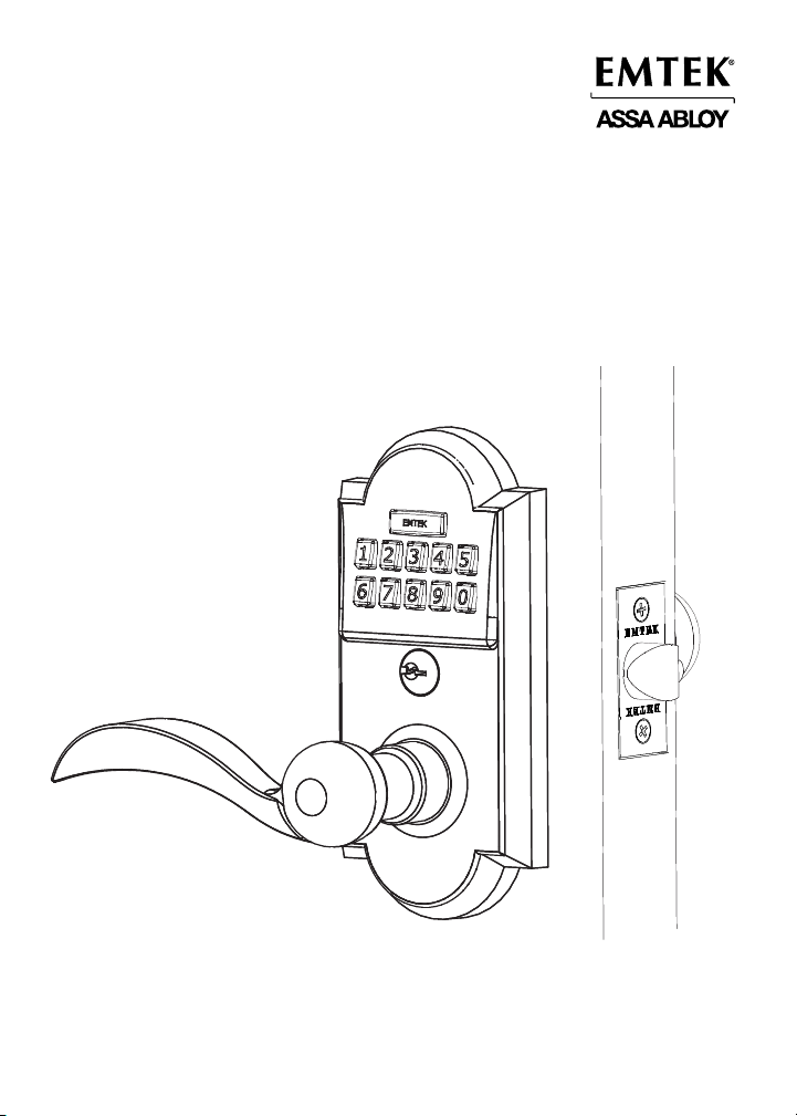
Installation & Programming Guide
Keypad Lever Locksets
ASSA ABLOY, the global leader in door opening solutions
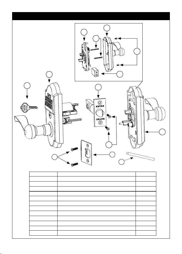
What’s in the Box
4a
2
1
6
4b
5
4c
4d
3
4
6
7
8
ITEM NO. DESCRIPTION QTY.
1 Metal Key 2
2 Outside Trim Plate Assembly 1
3 Latch Assembly
2 ⁄” or 2 ¾” Backset
1
4 Inside Trim Plate Assembly 1
4a Inside Chassis 1
4b Inside Trim Plate 1
4c #8-32 x ⁄" Flat Head Machine Screw 2
4d 9V Alkaline Battery - Type 6LR61 1
5 #8-32 x 1½" Flat Head Machine Screw 2
6 #8 x ¾" Wood Screw 4
7 Strike Plate 1
8 Plastic Extender 1
2
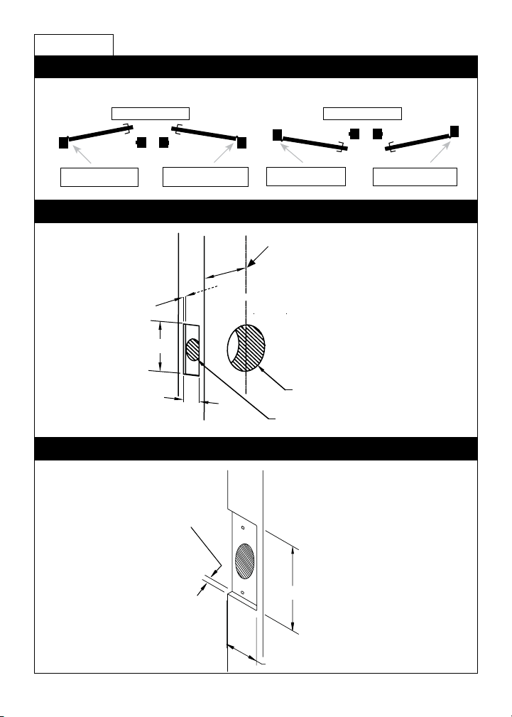
Preparation
1. Conrm Handing
HANDING OF DOOR IS ALWAYS DETERMINED FROM THE OUTSIDE
In-Swing Doors
Out-Swing Doors
Hinge is on the left.
Door is Left Hand (LH).
Hinge is on the right.
Door is Right Hand (RH).
2. Door Prep
⁄” Deep
2 ¼”
1 “
3. Remove Screws from Inside Trim Plate
3. Door Jamb Prep
⁄” Deep
Hinge is on the left.
Door is Left Hand (LH).
outsideoutside
2 ⁄” or 2 ¾” Backset
2 ⁄” Diameter Bore
1” Diameter Edge Bore
Hinge is on the right.
Door is Right Hand (RH).
2-3/4"
1 ½”
1-1/8"
2 ¼”
3
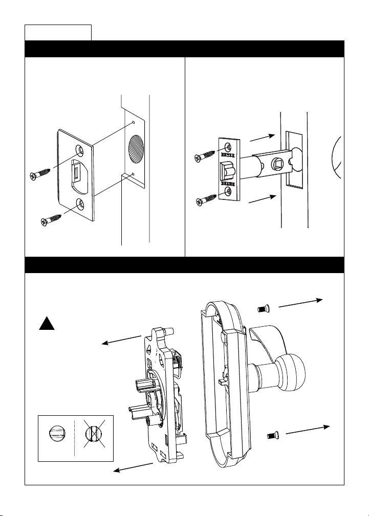
How to Install
1. Install Strike Plate & Latch
Step 1: Fasten Strike Plate using two
#8 x ¾” Wood Screws (item #6).
Step 2: Fasten Latch using two #8 x ¾”
Wood Screws (item #6).
2. Remove Screws from Inside Trim Plate
Use a Phillips head screwdriver to remove screws (item #4c) shown below and detach
Inside Trim Plate from the Inside Chassis.
Screws
!
REMOVE INSIDE
CHASSIS FROM
TRIM PLATE BEFORE
INSTALLING THE
OUTSIDE TRIM.
THUMBTURN MUST
BE IN LOCKED
POSITION.
(item #4c)
UnlockedLocked
4

3. Install Outside Trim Plate Assembly
Step 1: While holding Outside Trim Plate Assembly, Press the Plastic Extender (A) into
end of Spindle Shaft (B). The Shaft is properly aligned when the marking ‘TOP’ can be
seen from an overhead view.
!
THIS SIDE ON TOP.
B
A
Step 2: Position the Outside Trim Plate Assembly through the bore hole.
!
ONCE POSITIONED,
OUTSIDE TRIM PLATE
ASSEMBLY REQUIRES
SUPPORT.
Feed wire harness
through the bore hole.
Fit Plastic Extender
through latch.
Step 3: With the Outside Trim Plate Assembly ush to the door, REMOVE the Plastic
Extender.
5

4. Install Inside Chassis
Step 1: Conrm the position of Cam Link.
For Right Hand Locks:
!
CAM LINK MUST
REMAIN IN
THE CORRECT
POSITION DURING
INSTALLATION.
Step 2: Feed the Wire Harness through Inside Chassis.
Turn to right position.
For Left Hand Locks:
Turn to left position.
6

Step 3: Fasten Inside Chassis using two #8-32 x 1½”
Flat Head Machine Screw (item #5).
!
CHECK ALIGNMENT BEFORE
FULLY TIGHTENING SCREWS.
Step 4: Connect Wire Harness (A) and tuck Connectors as shown (B).
A
B
Step 5: Install Battery.
9V Battery
For optimal performance, always use a good quality battery.
7

5. Install Inside Trim Plate
Fasten Inside Trim Plate using two #8-32 x ⁄” Flat Head Machine Screws (item #4c).
!
USER CODES
ARE LOCATED
ON THE INSIDE
TRIM PLATE &
ON PAGE 11.
!
Inside
Correct for installation
*Locked - requires code
*Locked position is required for installation and removal of the Inside
Trim Plate Assembly.
(Does not apply to Keypad Storeroom/Gate product)
Incorrect for installation
Unlocked
!
THUMBTURN MUST BE IN
LOCKED POSITION FOR
INSTALLATION.
Screws (item #4c)
8

How to Use
Your Lock is Ready to Use
Your Emtek lock is shipped with two 4-digit user codes and a 6-digit
programming code. These codes are randomly generated at the factory.
(Turn to next page for Programming Instructions.)
To Unlock:
1. Enter 4-digit user codes.
(See sticker located on the inside
trim plate or on page 11).
2. Turn Handle.
Passage feature
(Does not apply to Keypad Storeroom/Gate product)
Activate by turning the inside thumbturn to the unlocked position.
This will engage the outside lever so a code is not required to enter.
To Lock:
1. Rotate Thumbturn from inside.
Locked Unlocked
9

How to Program
Programming Your Lock
In order to perform each of the following six functions, the lock must rst be
placed in Programming Mode:
1. Press and hold EMTEK button for 3 seconds
2. Yellow LED ashes, then remains solid*
3. Enter Programming Code
4. Green LED ashes, then 2 beeps
5. Yellow LED remains solid (awaiting button press; see following Table)
If you wIsh to Press
Change
Button
1
Programming
Code
(6 digits)
Add User Code
2
(4 digits)
(Maximum of 20
User Codes)
Delete User Code 3
Enable/Disable
**
All User Codes
Delete All User
4
5
Codes
Turn Beeper On/
6
Off
*If no input within 10 seconds, Yellow LED goes out, Red LED ashes and lock exits Programming Mode.
**Also referred to as “vacation mode”. This command temporarily disables all user codes (metal key
override will still work).
ActIons IndIcAtors
Enter New
Programming
Code
(6 digits)
Enter New
User Code
(4 digits)
Enter User
Code to be
Deleted
Entering ‘4’ disables all Users
(enables all if disabled)
Re-Enter Programming Code
Entering ‘6’ turns OFF (or ON)
Re-Enter
New
Programming
Code
(6 digits)
Re-Enter
New User
Code
(4 digits)
Re-Enter
User Code to
be Deleted
• 1 Green LED ash
• 1 beep
• 1 Green LED ash
• 1 beep
• 2 Green LED ashes
• 2 beeps
• 1 Green LED ash
• 1 beep
• 1 Green LED ash
• 1 beep
• 2 Green LED ashes
• 2 beeps
• 1 Green LED ash
• 1 beep
• 1 Green LED ash
• 1 beep
• 2 Green LED ashes
• 2 beeps
• 2 Green LED ashes
• 2 beeps
• 1 Green LED ash
• 1 beep
• 2 Green LED ashes
• 2 beeps
• 1 Green LED ash
• 1 beep
• 2 Green LED ashes
• 2 beeps
10

Keypad Operation - Beeper & LED Indicators
Function Indicators
Valid Code • 1 short beep, EMTEK button ashes
Invalid Code/Access Denied* • 1 Red LED ash
Lock-Out Mode Error • 2 short beeps
Access Accepted • 1 short beep
Low Battery • 4 Red LED ashes
Blackout Battery
Button Press Accepted • 1 Yellow LED ash
Outside Thumb Turn Enabled • 2 Green LED ashes
* If 3 consecutive incorrect codes are entered, the lock emits 4 short beeps and a ashing Red EMTEK
button. The lock will not accept additional input for 20 seconds (20 beeps).
Battery voltage has dropped too low; keypad will be disabled but metal key override will still work.
**
**
Green.
• 2 short beeps
• 1 short beep per second for duration
• 1 Green LED ash
• 4 short beeps
• 1 long Red LED ash
• 4 long beeps
• 1 Short Beep
Restoring the Lock to Factory Default Setting
This procedure clears the lock of all users and restores the Programming Code and
2 User Codes shipped with the lock.
• Remove power (disconnect 9V battery) from Lock
• Press and Hold EMTEK button
• Restore power (reconnect 9V battery) while continuing to hold EMTEK button
• Continue to hold EMTEK button for 3 seconds
• 1 Green LED Flash and 2 short beeps followed by 1 Green LED Flash and 2 short
beeps indicates the lock has been successfully restored
Place Sticker Here
IN8-KEYPADLL1 09/27/2010
11

Scan for how to
install videos.
ASSA ABLOY is the global leader in door opening solutions, dedicated to satisfying end-user needs for security, safety and
convenience.
Copyright © 2010, Emtek Products, Inc. an ASSA ABLOY Group company. All rights reserved. Reproduction in whole or in part
without the express written permission of Emtek Products, Inc. is prohibited.
 Loading...