

Page 1
RCM Installation and Application Notes
RCM-42B and RCM-82B
06-12-2003
Emtech Electronics, Inc. 564 So. 1325 West, Orem, Utah 84058 1-800-371-2102 1-801-426-8333
Page 2

RCM-42 and RCM-82 Installation and Application Notes
Quick Start Installation Guide for the RCM-42B & RCM-82B
Description:
The Emtech Electronics Room Combining Matrices are designed to simplify the process of connecting sound systems
in multiple rooms. The RCM-42B allows the sound systems from up to four rooms to combine in any combination
desired, while the RCM-82B does the same for up to 8 rooms. Each room may be operated independently, or it may be
assigned to either of two program groups, where it shares program material with any other room assigned to that same
group. The input channels of the matrix are normally directed back to their corresponding output.
Each room control has a Group A control input signal and a Group B control input signal (see figure 1). When either of
these control inputs are connected to ground, (with a switch closure to ground) the corresponding local input is
redirected to one of two internal busses, Group A or Group B which in turn are directed to the RCM output for that
room. If the control inputs are left in an open (switch is open) condition, the local material for that room is connected
to that room's output of the RCM only.
In any event, if program Group A or B are selected, all of the mic or line inputs that are available for that room in the
local position, continue to be available in the Group A or B positions.
Selecting between either of the two program groups is accomplished with an SPDT switch with a center off (open)
position. The use of solid state analog switches eliminates pops or clicks when switching. Signal level remains constant
as rooms are switched in or out of a group. The balanced inputs and DC logic buss combining controls allow long input
and control lines to the unit. If you are using the Emtech Electronics IA-204R amplifiers in your application, the
previously mentioned SPDT switch is built into the front panel of each amplifier. If you are using other amplifiers and
mixers, you can order from two decora style switch panels, RCM-KS (key-switch version) and RCM-S (standard
rocker style switch) from Emtech that provides the needed switch for each room.
Installation:
The RCM-42B and RCM-82B are fully remote controlled and can be placed in any convenient location. The unit may
be mounted to a wall or other flat surface using four #6 screws through the holes in the mounting flanges. All
connections to the unit are made by means of removable terminal connectors. the RCM can be mounted and then easily
wired at a later time. Avoid installing the unit in close proximity to large power transformers or power lines. (AC
current hum and noise may be introduced into the audio program.)
The RCM-B units now come with their own 24 volt DC power supply. You make the power connection via the DC
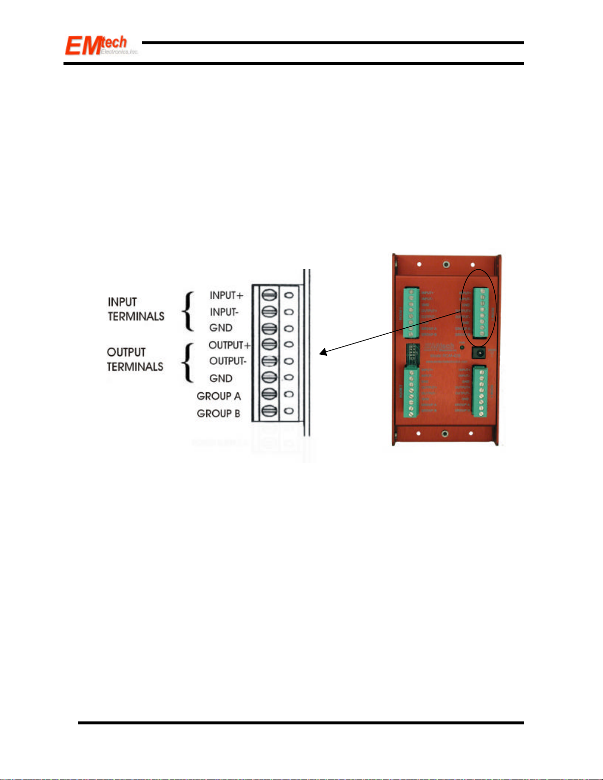
power jack on each unit. All other connections are made via 8-pin terminal connectors. Figure 1 includes a picture of
the 8-pin terminal connector.
2003, Emtech Electronics, Inc. All rights reserved.
2
Page 3
RCM-42 and RCM-82 Installation and Application Notes
The input connection terminals are shown in Figure 1. The input signals can come from any balanced or unbalanced
line level source such as a mixer/amplifier. The shield of a balanced line should be connected to the terminal marked
GND on the matrix. When the source is unbalanced, strap the "input -" terminal to the GND terminal. Whether the
source is balanced or unbalanced, shielded audio cable should be used for these connections to minimize noise and hum
pickup. The output connection terminals are also shown in figure 1. The output signal can be sent to any line level
input, such as a mixer/amplifier. As with the output connections, shielded audio cable should be used.
The two control inputs terminals for each room/buss are marked GROUP A and GROUP B as shown in Figure 1.
These two connections can be wired to remote switches; a simple closure to ground will then assign that room to the
corresponding combining group. When Group A and Group B control terminals are open, (not connected to ground)
the input signal is simply routed back to its corresponding room output.
Figure 1: Terminal Connections on RCM-42B
2003, Emtech Electronics, Inc. All rights reserved.
3
Page 4

RCM-42 and RCM-82 Installation and Application Notes
Block Diagram
If a given input's Group A (or B) control terminal is connected to ground, that input will be mixed with all other room
inputs with corresponding Group A (or B) terminals connected to ground. The mixed signal will be routed back to each
of the outputs with inputs assigned to that group. A room cannot be assigned to both Group A and Group B
simultaneously; if both the Group A and Group B terminals on a room are connected to ground, the input signal is
routed directly back to the input (in Local mode). Figure 2 shows the internal switching operation of the RCM-42 and
RCM-82.
Figure 2: Block Diagram of the RCM-42B (RCM-82B is identical, but with eight IO pairs)
2003, Emtech Electronics, Inc. All rights reserved.
4
Page 5

RCM-42 and RCM-82 Installation and Application Notes
Applications:
Customized Diverse System
The RCM-42B and RCM-82B can be used with any mixer/amplifier combination with line level outputs, or as a standalone zone control/distribution/summing unit. Figure 3 shows the different ways that the RCM-42 can be wired in a
combining application.
IA204R
RCM-S Switch
Amp/Mixer/Switch
Mixer
Amplifier
Amplifier
Room One
IA4206 Mixer
Room Two
Room Three
ISA253 Amp/Mixer
Room Four
RCM-KS
Figure 3
Room One is shown implemented with a standard pre-amp/mixer and amplifier of your choice, with an Emtech RCMS switch to control the RCM-42B.
Room Two is shown using an Emtech Electronics IA-4206 six channel pre-amp/mixer for six mic or line inputs. It also
provides tone controls. An Emtech RCM-KS key switch provides the RCM-42B program select capability. This switch
helps secure the system from tampering since the key can be removed in any of the three positions. All that is required
to finish the room sound reinforcement, is an amplifier with speakers.
2003, Emtech Electronics, Inc. All rights reserved.
5
Page 6

RCM-42 and RCM-82 Installation and Application Notes
Room Three is shown using an Emtech Electronics IA204-R including mic/line level inputs, pre-amp, mixer, 20 watt
amplifier and integrated RCM switching. This in-wall amplifier/mixer includes a locking cover to prevent tampering.
The IA204-R single unit coupled with speakers provides the entire sound reinforcement package for a small room.
Room Four utilizes an Emtech ISA-253 two channel mic/line pre-amp/mixer and 15 watt amplifier with an Emtech
RCM-S switch to control the RCM-42B. This in-wall amplifier/mixer also includes a hinged locking cover. All that is
needed to complete the solution, are speakers.
Smart Distribution Amplifier
The RCM-42B and RCM-82B can also be used as smart distribution amplifiers. Figure 4 shows how a RCM-42B can
be used as a smart distribution amp. A simple bank of switches allows remote selection of the active outputs. Using an
RCM-82B, up to eight outputs can be distributed.
2003, Emtech Electronics, Inc. All rights reserved.
6
Page 7

RCM-42 and RCM-82 Installation and Application Notes
Remote Source Selection
The RCM-42B and RCM-82B can also be used as a remote source selector. Figure 5 shows a way of remotely selecting
one of two program sources to feed a number of rooms. Rooms 1 and 2 can select between music source A or B. Using
the RCM-82B , six rooms can have independent remote selection of two program sources.
Connections:
When using the room combining switch on an Emtech Electronics product, from the IA-204 series, the ground pin for
the room combining function does not need to be connected as long as the IA-204 amplifier and the RCM 42B or
RCM-82B share a common power supply. If each unit has a separate power source, then you will need to make sure
that the ground pin is properly connected.
All amplifiers should have balanced inputs for best operation. If any amplifiers have unbalanced inputs, then the RCM42B or RCM-82B should be located as close as possible to the amplifiers inputs.
The shields of any interconnecting cables should be grounded at one end only. A terminal point is provided on each of
the RCM-42B or RCM-82B connectors for grounding both the input and output shields (See Figure 1).
For best results, limit the length of wire between the source selection switches and the RCM to 200 feet.
If you have any suggestions or questions, please call or write us at:
Emtech Electronics, Inc.
564 So. 1325 West, Orem, UT 84058
Voice: 1-800-371-2102 / 801-426-8333
Fax: 801-426-8334
www.emtechelectronics.com
2003, Emtech Electronics, Inc. All rights reserved.
7
 Loading...