

Page 1
IA-250
2 Ch. Mixer / 20W Class D Amp
09/2008
Emtech Electronics, Inc. 1126 N. 1200 West, Orem, Utah 84057 1-866-200-2878 801-426-8334 (fax)
Page 2
IA-250 2 Ch. Mixer/20W Class D Amp
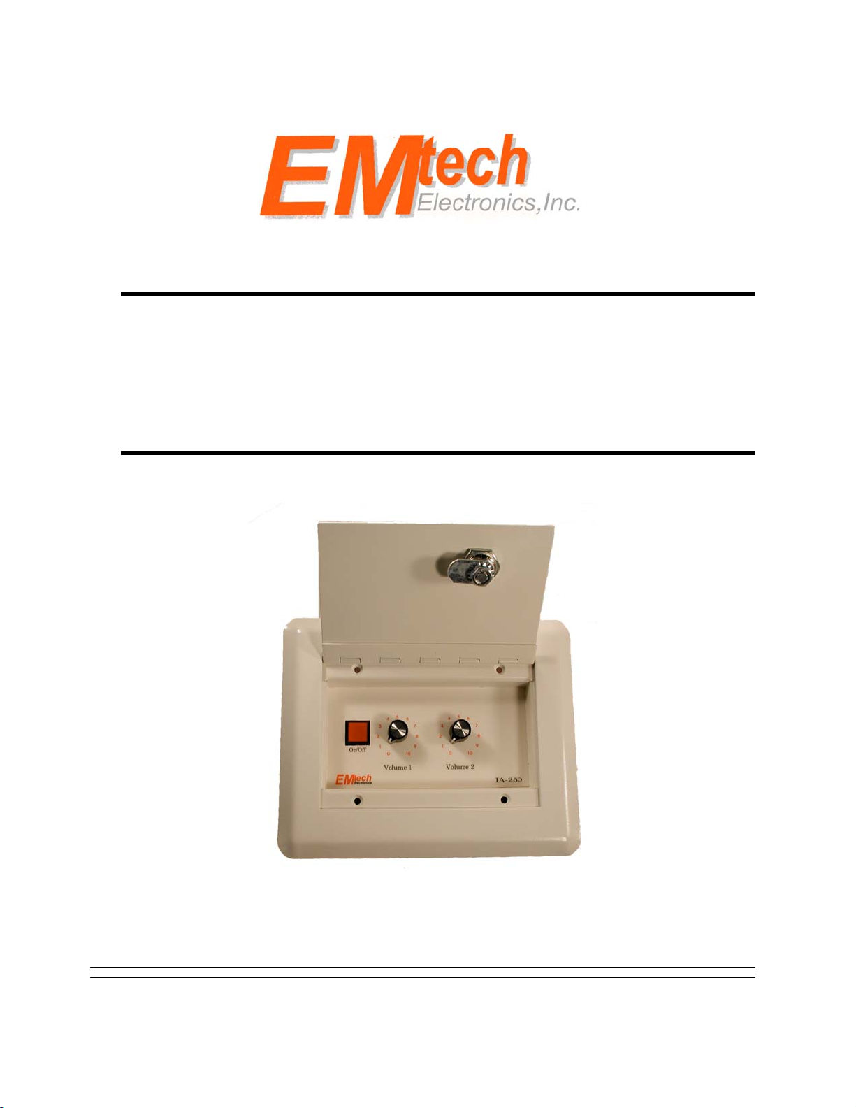
The IA-250 is a two channel mic/line audio mixer, and 20W Class D amplifier mounted in a 3-gang
in-wall box. It was designed to be compact and easy to operate, while providing high quality sound
reinforcement for a small room. Powered by it’s own 24Vdc plug-in power supply, the IA-250
means that your requirement for sound reinforcement is no longer dependent on the presence of an
19” rack.
Installation Overview
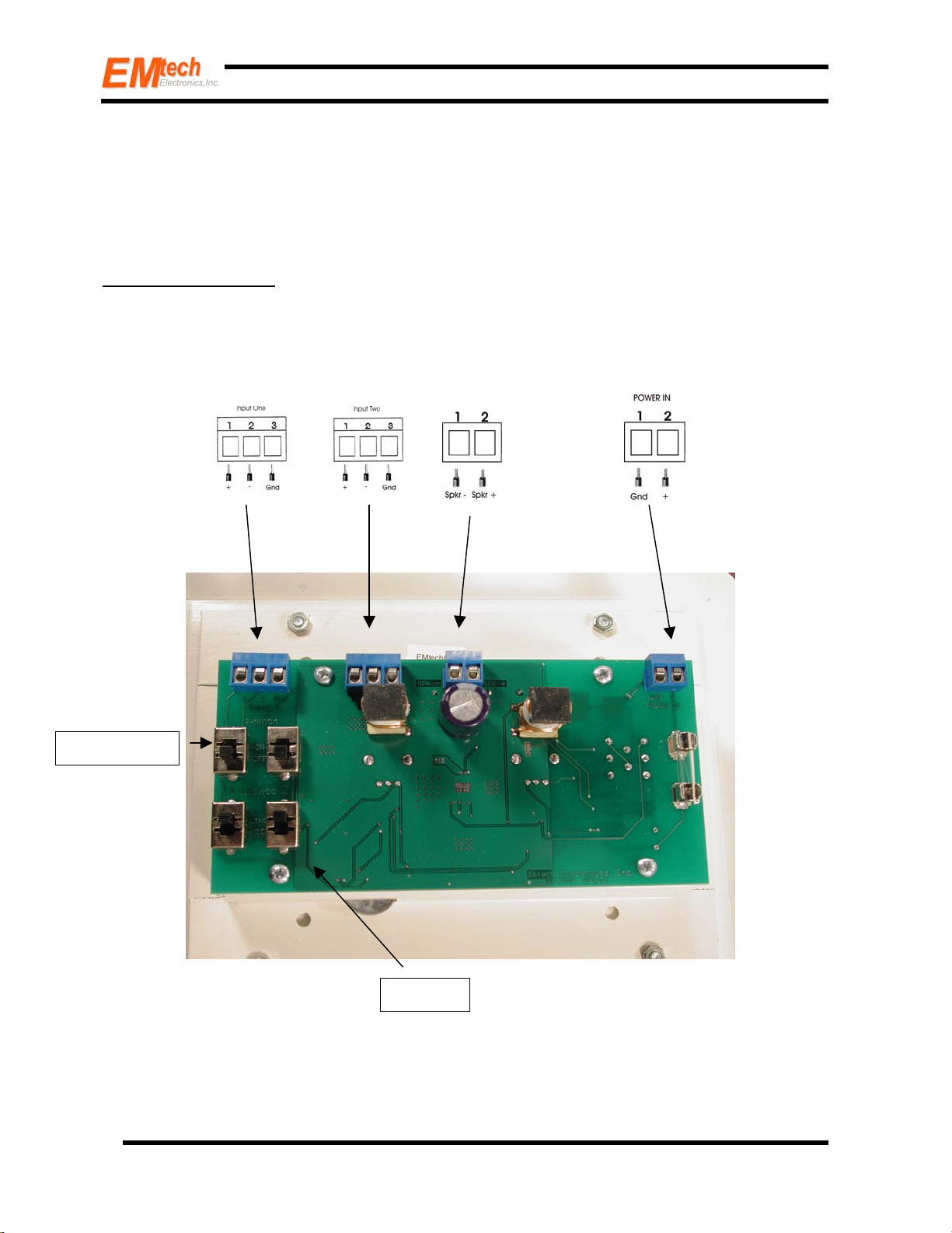
Setting up the IA-250 is quite easy. Please refer to the back of the IA-250, where terminal and
switch positions are etched in the copper, or to figure 1 below.
Phantom Pwr
©2008, Emtech Electronics, Inc. All rights reserved.
Mic/Line
Figure 1 : Backside of the IA-250
2
Page 3

IA-250 2 Ch. Mixer/20W Class D Amp
Setting up the IA-250 requires selecting between microphone or line input for each mixer channel,
and selecting between phantom power or no phantom power for each mixer channel. After making
those selections, wiring the inputs, speaker output and applying power is all that is required to
complete the installation.
Installation
The IA-250 Mixer/Amplifier should be mounted into a standard 3-gang in-wall box. Make sure
that the box is pre-mounted in the correct location, and that the wiring from microphones or line
inputs, the speakers, and the power supply have been fed to the in-wall box prior to installing the
IA-250.
Step One: Locate the mic/line selector switches on the back of the IA-250. The mic/line selector
switches are the two bottom switches on the printed circuit board (see figure 2 below). Select the
input for each mixer channel by choosing between mic or line.
Step Two: Phantom Power Switches
Channel 1 is the left switch, and channel
2 is the right switch. Putting the slider
in the up position turns on phantom
power for the channel, and putting the
slider in the down position turns off
phantom power to the channel.
Step One: Mic/Line Switches
Channel 1 is the left switch, and channel
2 is the right switch. Putting the slider
in the up position selects line input for
the channel, and putting the slider in the
down position selects microphone input
for the channel.
©2008, Emtech Electronics, Inc. All rights reserved.
Figure 2
3
Page 4

IA-250 2 Ch. Mixer/20W Class D Amp
IA-250 Switches
Step Two: Locate the phantom power selector switches on the back of the IA-250. The phantom
power switches are the two top switches on the printed circuit board (see figure 2 above). Select
phantom power for mixer channels by choosing between on or off.
Note: Phantom power is supplied on microphone inputs to provide power to a microphone, so
a channel being set-up for line input should have phantom power turned off.
Step Three: Hook-up the inputs to channels 1 & 2. Both of these inputs are 3-pin terminals on the
upper left side of the printed circuit board (see figure 1 above). Input 1 is the terminal on the far
left, and Input 2 is to the right of Input 1. Correct wiring for the terminals is provided in the figure
1 illustration.
Step Four: Hook-up the outputs to the speaker or speakers. The speaker hook-up is the 2-pin
terminal located in the upper middle of the printed circuit board (see figure 1 above). The negative
wire goes to pin 1, and positive to pin 2, as shown in the figure 1 illustration.
Note: Emtech offers two different speaker distribution products designed to help simplify the
wiring of speakers. The SD-8 simplifies parallel wiring for up to six 8 ohm speakers, while
the SD-70V converts the 8 ohm output of the IA-250 to 70.7 volts and distributes the signal
for up to six 70V speakers.
Step Five: Hook-up the 24Vdc power supply. The power hook-up is the 2-pin terminal located on
the upper right side of the printed circuit board (see figure 1 above). The power ground connection
goes to pin 1, and the +24Vdc goes to pin 2, as shown in the figure 1 illustration. The IA-250 is
supplied with a dedicated +24Vdc regulated power supply. The ground wire on the power
supply has lettering printed down the length of the wire.
Note: Do not substitute another power supply. The power supply that comes with the IA-250
was selected specifically to provide optimum performance of the product. If any problems
with the power supply occur, contact the factory for a replacement.
Once all of the connections have been made according to these instructions, fasten the IA-250 into
the 3-gang in-wall box using the four screws provided with the mixer/amp. Plug-in the power
supply once the IA-250 is securely mounted into the in-wall box. Installation is now complete –
turn on the IA-250.
©2008, Emtech Electronics, Inc. All rights reserved.
4
Page 5

IA-250 2 Ch. Mixer/20W Class D Amp
Emtech Electronics, Inc.
1126 N. 1200 West, Orem, UT 84057
Voice: 1-866-200-2878 / 801-426-8333
Fax: 801-426-8334
www.emtechelectronics.com
Specifications
Rated Power . . . . . . . . . . . . . . . . . . . . . . . . . . . . . . . . . . . . . . . . . . . . . . . . . . . . . .23 Watts @ 1Vrms
Line Input Sensitivity . . . . . . . . . . . . . . . . . . . . . . . . . . . . . . . . . . . . . . . . . . . . . . . . . . . . . . . . . . . 1v
Microphone Input . . . . . . . . . . . . . . . . . . . . . . . . . . . . . . . . . . . . . . . . . . . . . . . . . . . . Balanced Lo-Z
Total Harmonic Distortion . . . . . . . . . . . . . . . . . . . . . . . . . . . . . . . . . . . . . . . . . . . . . . . . . . . . 0.022%
Number of Channels . . . . . . . . . . . . . . . . . . . . . . . . . . . . . . . . 2- Switchable Microphone/Line Level
Number of Outputs . . . . . . . . . . . . . . . . . . . . . . . . . . . . . . . . . . . . . . . . . . . . . . . . . 1- 8 ohm Speaker
Power Requirements . . . . . . . . . . . . . . . . . . . . . . . . . . . . . . . . . . . . . . . . . . . . . . . . +24Vdc @ 1.05A
Dimensions . . . . . . . . . . . . . . . . . . . . . . . . . . . . . . . . . . . . . . . . . . . . . . . 6.0” H X 7.5” W X 2.25” D
Weight . . . . . . . . . . . . . . . . . . . . . . . . . . . . . . . . . . . . . . . . . . . . . . . . . . . . . . . . . . . . . . . . . . . . 1 lbs.
Warranty
Emtech Electronics, Inc. warrants the IA-250 for a period of one year, from the original date of
purchase, against defects in parts and workmanship. If a defect occurs, the unit will be repaired or
replaced, at our option, free of all charges if delivered prepaid to the factory. Warranty does not
extend to finish, appearance, abuse or defects due to the misuse or operation under other than
specified conditions, nor does it extend to incidental or consequential damages. Repair by anyone
other than Emtech will void the warranty.
©2008, Emtech Electronics, Inc. All rights reserved.
5
Page 6

IA-250 2 Ch. Mixer/20W Class D Amp
©2008, Emtech Electronics, Inc. All rights reserved.
6
 Loading...