

Page 1

IA-204 SERIES
OF
IN-WALL AMPLIFIERS
INSTALLATION MANUAL
©Emtech Electronics, Inc. 1126 N. 1200 West Orem, Utah 84057 1-866-200-2878
Page 2

IMPORTANT
SAFETY INFORMATION
FOR YOUR SAFETY
To ensure safe operation, all connections between the power supply and the mains should be made by a
qualified person, and approved by local government inspectors. The fact that the equipment operates satisfactorily does
not imply that the power point is properly grounded and that the installation is completely safe. For your safety, we
recommend that the mains connections be made only by a licensed electrician.
WARNING
Power source voltage of this unit is listed on the power supply. Do not fail to connect to the correct voltage.
Refer to the power supply diagram included with the power supply for proper connections. Avoid extremes in
temperature and humidity. To prevent fire or shock hazard, do not expose this product, or anything that is connected to
it, to rain or any type of moisture. To prevent shock hazard, do not handle this device or any device connected to it if
you are wet or if you are standing in any moisture.
LIABILITY
Emtech Electronics does not accept any liability for injury or damages to persons or property due to the
improper use or application of this equipment. Furthermore, no liability is assumed for any lost time or earnings due to
the failure of this equipment to operate properly other than the terms and conditions outlined in the Warranty. No other
warranties are expressed or implied.
2
Page 3

INTRODUCTION
Thank you for choosing an Emtech Electronics Product. The IA-204 series of In-Wall Amplifiers are the
intelligent solution for single and multi-room sound reinforcement applications were rack space does not exist for a
sound system. The IA-204 system requires no special training for your personnel or guests. There are no confusing,
elaborate programming sequences necessary to adapt the system to different room configurations. Room combining is
achieved effortlessly with the flip of a switch.
SYSTEM FEATURES:
• 25 watt (into 4 ohms), 2 input amplifiers (IA204R, IA-204S)
• Each input is mic/line selectable
• Balanced mic (with Phantom Power) and balanced line inputs
• Amplifiers mount into 4 gang deep masonry boxes (RACO 698)
• Eliminates need for costly rack mounts
• Locking security cover plate
• Uses remote 24 VDC power supply
• Low cost and quick installation
• Room combining matrix available for 4 rooms (RCM-42B) and 8 rooms (RCM-82B)
• Perfect for Conference Rooms, Convention Centers, Churches, Schools, etc.
MODEL IA-204P
• The IA-204P has no internal power amplifier. It is for use with an external power amplifier. Otherwise it has
the same front panel features as the IA-204R.
• SEND – and SEND + are the balanced line output.
• Features a three position ROOM MIXING switch on front panel.
• ROOM MIXING switch works with the Emtech RCM-42B (Room Combining Matrix, 4 room 2 buss)
available separately.
• ROOM MIXING switch allows up to four IA-204’s to share program material on either the GROUP A or
GROUP B buss.
MODEL IA-204R
• The IA-204R is similar to the IA-204P except it does have an internal 25watt (into 4 ohms), 2 input power
amplifier.
• The IA-204R features a ROOM MIX Switch on its front panel. Like the IA-204P, this switch connects to
the optional Emtech RCM-42B Room Combining Matrix (see section on the RCM-42B), and allows up to
four IA-204’s to share program material on either the GROUP A or GROUP B buss.
MODEL IA-204S
• The IA-204S has an internal 25 watt (into 4 ohms), 2 input power amplifier.
• The IA-204S features a SPEAKER ZONE switch that allows for user control of two speaker zones. This
feature can help reduce feedback from head table speaker zones (see section on speaker zones).
See Figure 6 for speaker zone wiring details. This diagram shows how to arrange the speakers in a bridge
pattern allowing for greater flexibility and control.
• Requires an external switch for Room Combining if using the optional RCM-42B.
SYSTEM OPERATION
3
Page 4
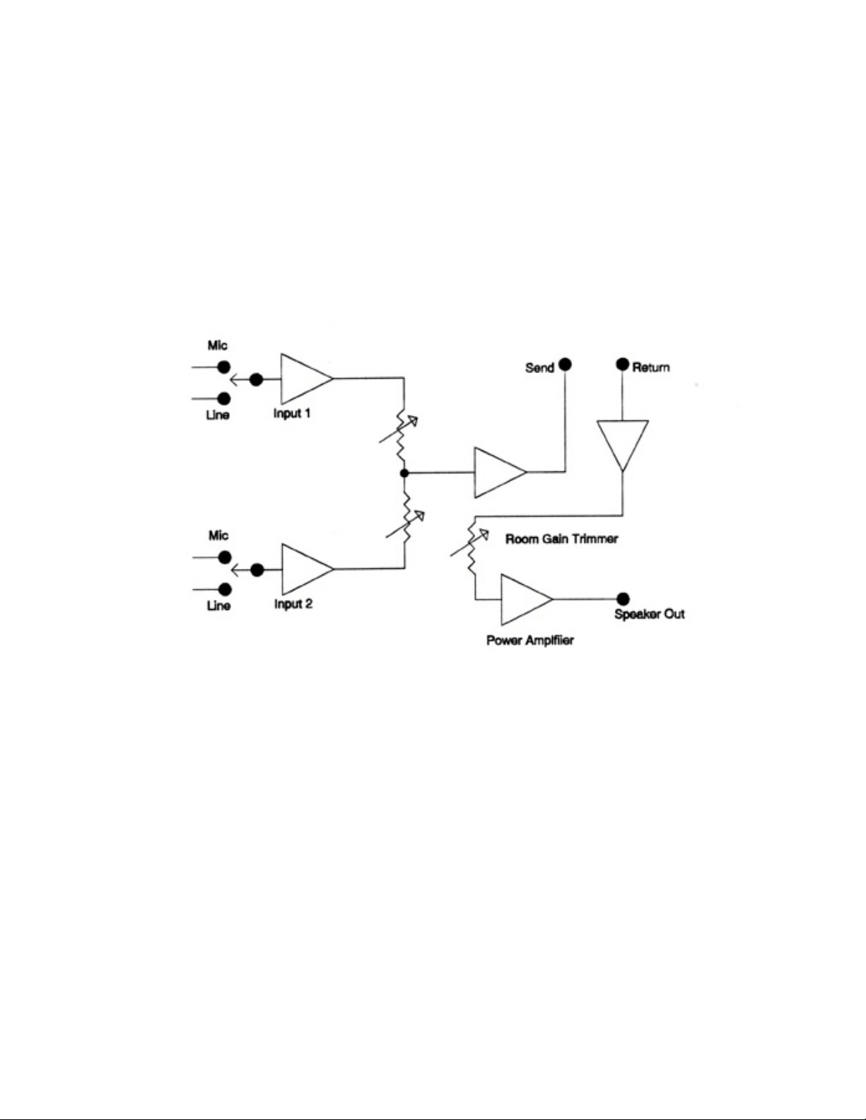
Operating the IA-204 series of in-wall amplifiers is simple. Just follow these three steps:
1. Turn the POWER switch to the ON position (LED will illuminate).
2. Set your input source on INPUT 1 or INPUT 2 to either mic or line using the switches.
3. Adjust VOLUME control for the desired sound output.
Simplified Block Diagram of the IA-204 In-Wall Amplifier
SITE PREPARATION
4
Page 5
IA-204
Location
• The suggested mounting height for the IA-204 is approximately 48” – 66” from the floor.
• The mounting location for the IA-204 depends upon many factors, such as the room layout, input location,
distance to the power supply, etc.
Mounting
• The IA-204 fits into a common 4 gang deep masonry electrical box (RACO 698 or equivalent).
• Four painted mounting screws (6-32 x 1” flathead Phillips) are provided to secure the IA-204.
BACK BOX MOUNTING
• WARNING! If using conduit, not all of the conduit access holes in the 4 gang box can be used. Please
follow these recommendations exactly! These directions assume the 4 gang box is mounted on a vertical
wall. Before any installation is started, verify whether or not the IA-204 is to use the back-mounted 70 volt
line transformer. (Emtech model number T-70V).
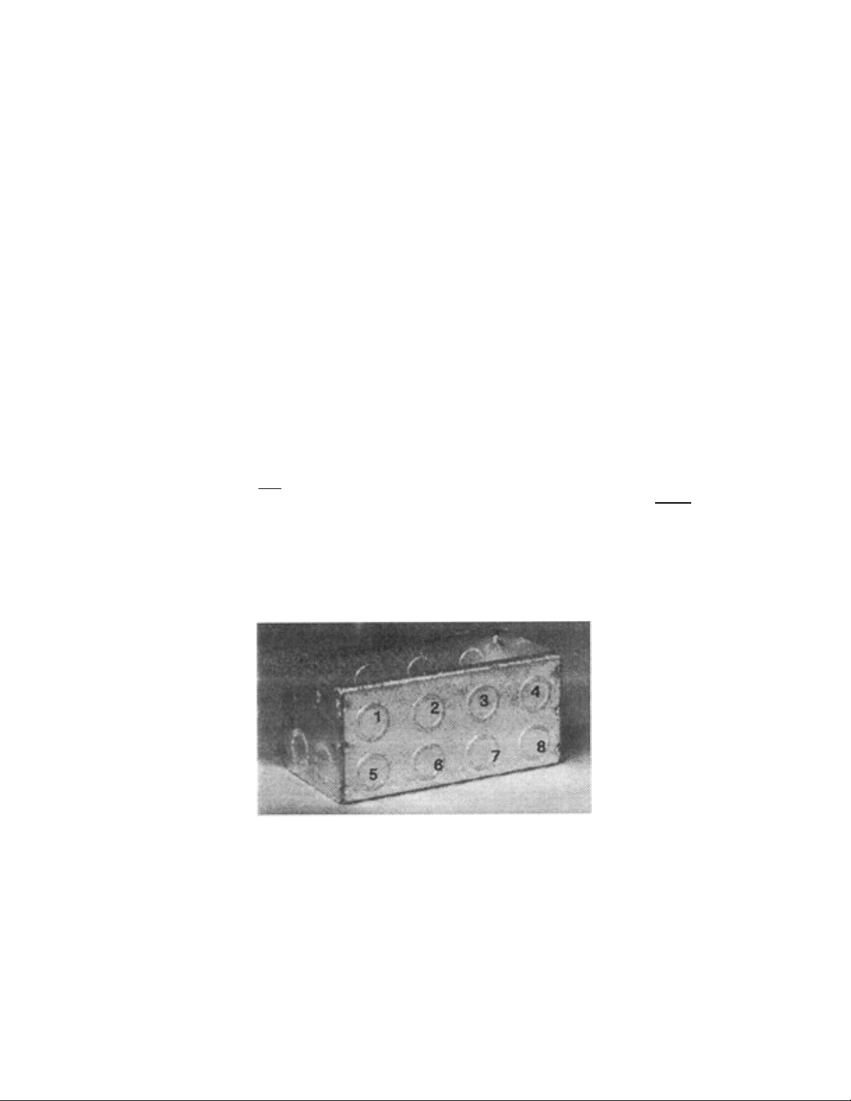
NOTE! The IA-204 is designed to fit into a RACO 698 4 gang deep masonry electrical box. The following directions
assume you are using the T-70V 70 volt line transformer. This optional transformer was designed for the IA-204
System. These directions are applicable only if using a RACO 698 box.
• The picture to the right shows the RACO 698 box. This is a view of the bottom of the box with 8 conduit
knockouts. Use only the 3 knockouts (labeled 6, 7 and 8) toward the lower right hand side of the picture!
When the box is installed in the wall, these are the back knockouts on the right side of the box. Do not use
the 4 knockouts near the top lip of the box (labeled 1, 2, 3 and 4)!
• The top of the box also has 8 conduit knockouts. Use the 3 knockouts on the top that are directly above
knockouts 6, 7 and 8 on the bottom.
• The 2 conduit knockouts on the right side of the 4 gang box can be used.
RACO 698 4 Gang Deep Masonry Electrical Box
• Do not use the 2 conduit knockouts on the left side of the box! (They are visible in the photograph
above).
POWER SUPPLY
5
Page 6

NOTE - This information is applicable only to the power supplies available from Emtech Electronics. If you
choose to use a different power supply, please follow the manufacturers instructions.
Location
• A central location is most desirable for the power supply.
• Keep the distances between each IA-204 and the power supply as short as possible.
• The following wire gauges are recommended, depending upon the distance from the power supply to the IA-
204:
Gauge Distance
18 AWG 0 to 50 feet
16 AWG 50 to 200 feet
14 AWG 200 to 300 feet
Longer distances are not recommended.
Mounting
• The DC power supplies, available from Emtech Electronics (PS-30, PS-60, PS-90 & PS-100), can be
mounted into a Hoffman A-SE 10 X 10 X 4 or equivalent (10” x 10” x 4”) electrical box. If another type or
style of box is chosen, make sure that it is approved by local building codes.
• Securely mount the supply in the Hoffman A-SE 10 X 10 X 4, and mount this box at the desired location in
accordance to local building codes.
• If the RCM-42B is to be mounted at the power supply location, it can be mounted in the same box as the
power supply.
• The Emtech power supplies are conservatively rated and under normal use will not become excessively hot.
Note: The DC power supplies (PS-30, PS-60, PS-90 & PS-100) provided by Emtech are manufactured by
Tamura Corporation, and they are all UL/CSA/VDE listed supplies. Do not use any uncertified power supplies
in your in-wall installations.
Wiring
• Follow local building codes when connecting the power supply to the AC power mains.
• The recommended Emtech power supplies can be wired for three possible primary input voltages; low,
normal, and high. They are factory set for normal. See the directions included with the power supply for
more details.
• If your IA-204 installation uses electrical conduit in between each amplifier, make sure that the negative (-)
DC output lead from the power supply is electrically connected to the conduit. Also, make sure that each IA-
204 has a good electrical connection (ground) to that conduit. The four screws that connect the IA-204 to the
4 gang box should not be depended upon to make a reliable ground connection. Proper grounding will
minimize the possibility of hum problems, ground loops, and oscillation within the system.
• All connections between the power supply and the electrical mains should be made by a licensed electrician
and should meet with all local building codes.
• If a 70 volt distributed system is installed, metal conduit may be required in some places. Consult local
building codes for details.
6
Page 7

CONNECTING THE IA-204
WIRING
• Microphone and line input signals require shielded cables.
• If using the RCM-42B Room Combining Matrix, use shielded cables to connect the RETURN and SEND
between the IA-204 and RCM-42B. Each IA-204 is shipped with jumpers on the seven pin orange screw
terminal connector between pins 4 and 6, and 5 and 7. These need to be removed if you are using the RCM-
42B. These jumpers are necessary to connect the SEND and RETURN when no RCM-42B is connected.
• A two conductor non-shielded wire is used to connect the ROOM MIXING switch to the RCM-42. If you
are using a remote room combining switch, separate from the IA-204, you will need a three conductor wire
(see room combining section for more detail).
• Ground all cable shielding only at the IA-204! Do not ground mic or line inputs to conduit, as this can create
ground loops and cause noise and system oscillation.
• All cables should be brought at least 6” beyond the 4 gang electrical box for ease of installation and future
service.
• All connections should be terminated with the proper connectors supplied with the IA-204.
• To avoid electrical interference, signal cables should not run close to exposed high voltage wiring.
• Be sure to follow local building codes.
RECOMMENDED CABLES
• The following cable types are recommended:
• 2 Conductor shielded for microphone and line inputs.
• 2 pair (each containing 2 conductors) individually shielded for SEND and RETURN
connections between the IA-204 and RCM-42B. (Belden 8723, West Penn 510, or
equivalent)
• 2 conductor non-shielded for the ROOM MIXING control lines (if using the RCM-
42B).
IA-204 INSTALLATION
WARNING! The IA-204 uses a bridging amplifier circuit. Do not ground either of the speaker outputs. If connecting
a headphone jack, make sure it is insulated from ground!
• All wiring to the IA-204 is low voltage and connects to the IA-204 with removable screw terminal
connectors.
• Remove the screw terminal connector from the IA-204, insert the bare wire end into the desired slot, and
tighten the screw to secure the wire in place.
• Verify all wire connections and take care not to reverse the screw terminal connectors when replacing them
on their respective circuit board terminals.
• When the screw terminal connectors are properly oriented, all wiring faces down toward the bottom of the 4
gang electrical box.
7
Page 8

IA-204P
Figure 3 shows the screw terminal connections for the IA-204P.
J1 10 PIN CONNECTOR
• PIN 1 Mic 1 and Line 1 ground
• PIN 2 Mic 1 + input
• PIN 3 Mic 1 – input
• PIN 4 Line 1 + input
• PIN 5 Line 1 – input
• PIN 6 Mic 2 and Line 2 ground
• PIN 7 Mic 2 + input
• PIN 8 Mic 2 – input
• PIN 9 Line 2 + input
• PIN 10 Line 2 – input
• Line level signals can be balanced or unbalanced. If you connect unbalanced line level signals, connect the
shield to both ground and the negative (-) terminal (pin 5 or pin 8).
J2 7 PIN CONNECTOR
• PIN 1 Power supply ground
• PIN 2 Power Supply positive 24 VDC input
• PIN 3 No connection
• PIN 4 Send - (Line Output)
• PIN 5 Send + (Line Output)
• PINS 6 and 7. The IA-204P does not have an internal power amplifier, so the RETURN - + pins serve
another function.
• PIN 6 connects to GROUP A. (This connects to BUSS A on the RCM-42B)
• PIN 7 connects to GROUP B. (This connects to BUSS B on the RCM-42B)
When using the optional RCM-42B Room Combining Matrix, the Room Combining Buss control signals from the
RCM-42B connect to Pins 6 and 7 of J2 on the IA-204R. This allows the ROOM MIX switch on the front panel of the
IA-204R to switch between LOCAL, GROUP A, and Group B.
Figure 3. Rear View of IA-204P Circuit Board
IA-204R
8
Page 9

Figure 4 shows the screw terminal connections for the IA-204R.
J1 10 PIN CONNECTOR
• Same as IA-204P
J2 7 PIN CONNECTOR
• PIN 1 Power supply ground
• PIN 2 Power Supply + input 24 vdc
• PIN 3 No connection
• PIN 4 Send-
• PIN 5 Send +
• PIN 6 Return –
• PIN 7 Return +
J3 For future expansion.
J4 3 PIN WHITE CONNECTOR: This connector is for the Emtech T-70V transformer connector. If you do
not order this transformer, a factory installed jumper is placed between pins 1 and 3.
J5 FOUR PIN CONNECTOR
• PIN 1 - Speaker A
• PIN 2 - Speaker B
• PIN 3 Room Mixing, Group B select, connects to the Buss B input on the RCM-42B room input that is
connected to this IA-204R
• PIN 4 Room Mixing, Group A select, connects to the Buss A input on the RCM-42B room input that is
connected to this IA-204 R
IA-204S
Figure 4. Rear View of IA-204R Circuit Board
9
Page 10

NOTE! When using the IA-204S with the RCM-42B Room Combining Matrix, you will need a single-pole, doublethrow center off switch to provide for control of the Room Combining feature. This switch connects to the same Room
Combining channel as the IA-204S.
Figure 5 shows the screw terminal connections for the IA-204S.
J1 10 PIN CONNECTOR
• Same as IA-204P
J2 7 PIN CONNECTOR
• PIN 1 Power supply ground
• PIN 2 Power Supply + input 24 vdc
• PIN 3 No connection
• PIN 4 Send-
• PIN 5 Send +
• PIN 6 Return –
• PIN 7 Return +
J3 For future expansion.
J4 3 PIN WHITE CONNECTOR: This connector is for the Emtech T-70V transformer connector. If you do
not order this transformer, a factory installed jumper is placed between pins 1 and 3.
J5 FOUR PIN CONNECTOR (See figure 6 for more information)
• PIN 1 Speaker A (+)
• PIN 2 Speaker B (-)
• PIN 3 Speaker B (-)
• PIN 4 Speaker A (+)
Figure 5. Rear View of IA-204 S Circuit Board
Figure 6 shows how to wire the two IA-204S Head Table Speaker Zones:
10
Page 11

Step 1: Draw room speaker layout.
11
Page 12

Step 2: Circle desired Zone A and Zone B speakers.
Step 3: Connect speakers. Example below
Zone A or Zone B (Shaded)
Figure 7. Laying out Head Table Speaker Zones
TESTING & TROUBLESHOOTING
POWER SUPPLY
• The power supply voltage (24 VDC) and polarity should be checked at the connector of each IA-204 and
RCM-42B prior to connecting and turning the power on.
SPEAKERS
• Speakers should be tested for proper phasing (polarity) and correct wiring configuration with a multi-meter.
Verify speaker phasing (polarity) at the speaker connector to ensure maximum performance when 2 or more
rooms are combined.
IA-204
• Verify a microphone or line input is connected. If a line input is connected to the house background music or
paging system, verify that system is operative.
• Turn the IA-204 on and switch the mic/line select switch to the appropriate setting. Slowly advance the input
level control until the desired volume is reached.
IA-204P
• To test the IA-204P, verify the external power amplifier is properly connected and turned on.
IA-204R
12
Page 13

• If you are using the IA-204R with the ROOM MIXING switch, check the operation of the ROOM
MIXING switch by setting it to the GROUP A or GROUP B position on any two or more IA-204’s that are
connected to the RCM-42B and verify that they are sharing program material.
IA-204S
• If you are testing the IA-204S, and have two speaker zones pre-wired, check the speaker zones by switching
the SPEAKERS switch to the A OFF, ON, and B OFF positions and verifying the results.
NO SOUND, LED LIT
• Verify that the VOLUME control(s) are turned up to a normal range, and that there is a good input signal
present.
DISTORTED SOUND AT LOW VOLUME SETTING
• It is possible that the input signal is distorted or too high, thus over driving the input of the IA-204.
• Input signals should be matched to the system input sensitivity.
• Check adjustment of rear mounted trimmer pot.
LOW OUTPUT
• Verify that the VOLUME control(s) are turned up to a normal range, and that there is a good input signal
present.
• Check the signal level of the input source.
• Check position of rear mounted trimmer pot on each 204. It can be adjusted slightly to compensate for
excessively low level inputs.
• Input signals should be matched to the system input sensitivity.
SOME SPEAKERS NOT WORKING
• Re-check speaker wiring, connections, and polarities.
• Verify the SPEAKERS switch is set to the center ON position (for the IA-204S model).
• Make sure that all speakers have been properly tested, if they are wired in zones. Also check speaker
polarities.
NOTE
If the preceding checks do not correct the symptoms, then service should be referred to Emtech Electronics. There are
no user serviceable parts contained within the IA-204. For your own safety and to protect the warranty on the IA-204,
do not attempt any unauthorized repair of the IA-204.
ROOM COMBINING SYSTEMS
NOTE: This section is applicable only to IA-204 installations that use the RCM-42B Room Combining Matrix.
13
Page 14

Block Diagram of the RCM-42B
RCM-42B ROOM COMBINING MATRIX FEATURES
• Allows up to four IA-204’s to share program material.
• Provides two combining busses for your IA-204 system.
• Digitally controlled switching for ease of operation.
• Uses screw terminal connectors for fast and reliable installation.
• Silk screened label for error free installation.
• When in use, allows the power amplifier section of grouped IA-204’s to work as “slave” amplifiers, and
allows all mic/line inputs to act as “masters”.
14
Page 15

• Mount the RCM-42B in a convenient location, such as next to the power supply.
• There are 4 screw terminal connectors on the RCM-42B. Each of these connectors is labeled for a specific
room, room one through room four.
• The room one connector has two extra pins for the power supply inputs.
15
Page 16

• The INPUT – and INPUT + terminals are connected to the SEND – and SEND + wires from the IA-204.
• The OUTPUT – and OUTPUT + terminals are connected to the RETURN – and RETURN + wires from
the IA-204.
• The cables connecting the inputs and outputs between the IA-204 and the RCM-42B must be shielded.
Terminate the shielding at the RCM-42B only! Each orange connector on the RCM-42B has two terminals
labeled GROUND for this purpose.
• The BUSS A and BUSS B pins connect directly to the IA-204R. BUSS A connects to pin 3 (labeled C) on
J5 (4 pin orange connector), and BUSS B connects to pin 4 (labeled C) on J5.
• If using the IA-204S, a separate switch must be installed for room mixing. A single-pole, double-throw
center off switch is required for switching between GROUP A and GROUP B (called BUSS A and BUSS B
on the RCM-42B). A three conductor non-shielded cable is required because a ground connection must be
made from the RCM-42B to the middle pin of this switch.
• To combine rooms, change the ROOM MIXING switch on the IA-204R from LOCAL to GROUP A or
GROUP B. Repeat this step on any other IA-204R that is to be combined. IA-204’s on the same GROUP
setting can now share program material.
BALANCING EACH IA-204
• Each IA-204 has a trimmer control on the back of the circuit board. This control is used for balancing the
sound level in individual rooms so that when movable partitions are opened and the room combining feature
is used, the sound level is balanced room to room, regardless of room size or speaker configuration.
OPTIONAL METHOD OF BALANCING ROOM SOUND FOR ROOM COMBINING
• To set this control properly, pink noise should be fed into any one of the common area IA-204’s and its
ROOM MIXING switch should be set to one of the GROUP positions. Set the ROOM switch to the same
GROUP position on the other IA-204’s that are feeding the common area. Set the volume control of the
“master” IA-204 to the 12:00 position and the trimmer control(s) should be adjusted on the “slave” IA-204’s
while monitoring the sound pressure level with a SPL meter. After the sound level has been balanced in each
room, feed the pink noise into one of the “slave” 204’s that was adjusted previously and then adjust the
trimmer control on the 204 that was the “master” before until proper balance is achieved. Now, any IA-204
can be a “master” or a “slave” in perfect balance. Refer to operation section of this manual. Verify that
power is available to the IA-204 by turning on other IA-204’s sharing the same power supply.
16
Page 17

SPECIFICATIONS
Power Out……………………………………………………… ………………………….20 Watts RMS into 8 ohms.
………………………………………………………………………………………………25 Watts RMS into 4 ohms.
Mic Input Sensitivity.………………………………………………………………………………………………5 mV.
Line Input Sensitivity…………………………………………………………………………………………….100 mV.
Frequency Response…………………………………………………………………………………± 3dB 30 to 18Khz.
Distortion…………………………………………………………………………………………………Less than .04%.
Mic Input Impedance…………………………………………………………………………………………….3 k ohms.
Line Input Impedance…………………………………………………………………………………………...20 k ohms.
ACCESSORIES
MSC panels see MSC series brochure
MJ panels see MJ series brochure
EJ-10 Multi-Input Adaptor Box. Accepts mono or stereo line and speaker level inputs, allows seized
connection to the local telephone system and converts them to transformer balanced mic level
output. Includes cables and zippered nylon carrying case.
PS-30* Power Supply capable of powering one (1) IA-204. 24Vdc @ 1.2A
PS-60* Power Supply capable of powering up to two (2) IA-204’s. 24Vdc @ 2.4A
PS-90* Power Supply capable of powering up to three (3) IA-204’s. 24Vdc @ 3.6A
PS-100* Power Supply capable of powering up to four (4) IA-204’s. 24Vdc @ 4.8A
*All power supplies fit into a Hoffman (A-SE 10” x 10” x 4”) or equivalent electrical box.
17
Page 18

SERVICE
In the unlikely event that service should ever be required on your IA-204, first perform all of the checks in the
troubleshooting section of this manual. If the problem still persists, the IA-204 will have to be removed for servicing.
• Make sure that the IA-204 power switch is turned off.
• Loosen and remove the 4 screws that attach the unit to the 3-gang electrical box.
• Carefully pull the IA-204 straight out and extend the attached cables until the unit is clear of the mounting
surface and box.
• Gently remove the quick disconnect cable connectors from the rear of the IA-204 by pulling them straight
off.
• WARNING! Do not rock the connectors to loosen them or damage may occur.
To install the replacement IA-204, make sure that the IA-204 power switch is turned off, then plug the quick disconnect
cable connectors on to their respective pin locations. MAKE CERTAIN THAT THE CONNECTORS ARE
PROPERLY ALIGNED WITH THE CORRECT PINS BEFORE PLUGGING THEM IN. FAILURE TO DO SO
COULD RESULT IN DAMAGE TO THE IA-204! Once the connector has been properly aligned with the respective
pins on the IA-204, carefully press the connector down until it is firmly in place. Do not rock the connector while
placing it on the pins or the circuit board may be damaged. Carefully push the IA-204 into the 4 gang electrical box
until it is flush with the mounting surface. If resistance is felt, do not force the IA-204. Check the cables and arrange
them for maximum clearance for the IA-204 within the electrical box. Insert and tighten the 4 mounting screws to
secure the IA-204 in the box. Perform the Testing procedures found in the installation section of this manual.
If a failure has occurred in the PS-30, PS-60, PS-90 or PS-100 power supply, MAKE SURE THAT THE MAINS
POWER SOURCE HAS BEEN SHUT OFF OR DISCONNECTED BEFORE ATTEMPTING REMOVAL OF
THE POWER SUPPLY! If you are unsure of how to shut off or disconnect the mains power to the power supply,
consult a licensed electrician for help. After the mains power has been shut off or disconnected, disconnect all wires
from the power supply and clearly mark each wire as to its function and location on the power supply. Detach the
power supply and remove it from the electrical box that it is mounted in.
To install the power supply, MAKE SURE THAT THE MAINS POWER SOURCE HAS BEEN SHUT OFF OR
DISCONNECTED BEFORE ATTEMPTING REPLACEMENT OF THE POWER SUPPLY! If you are unsure
of how to shut off or disconnect the mains power to the power supply, consult a licensed electrician for help. After you
are certain that the mains power has been shut off or disconnected, identify each wire and attach them to the power
supply. Verify each connection before restoring mains power to the power supply. Replace all covers and secure with
all of the necessary hardware. Perform the Testing procedures found in the installation of this manual.
WARRANTY
Emtech Electronics warrants each IA-204 Series In-Wall Amplifier, RCM-42B Room Combining Matrix, and PS
Series Power Supply against defects in material or workmanship for a period of one year from date of delivery to the
original customer. This warranty is specifically limited to the replacement or repair (at our option) of any such defects,
without charge, when the complete unit is returned to Emtech Electronics, transportation charges prepaid. Emtech
Electronics shall not be liable for incidental or consequential damages. No liability is assumed for damages due to
accident, abuse, tampering with the IA-204, lack of reasonable care, loss of parts, or subjecting the IA-204 to input
values of a magnitude in excess of those specified. Repair by other than Emtech Electronics will void this warranty.
EMTECH ELECTRONIC, INC.
1126 NORTH 1200 WEST
OREM, UT 84057
801-426-8333 / 801-426-8334 FAX
1-866-200-2878
www.emtechelectronics.com
18
 Loading...