

Page 1

The BLU -CP is a pulpit control module for BSS
for connecting to the p ulpit motor .
BLU-CP Pulpit Control
BLU-CP Wiring Instructions
Audio London Series Digital Signal
Processors. It is built on a 2.5” X 6” aluminum
plate with a M ylar overlay on the f ront side of
the plate containing the int eg ra ted switch es and
status LED’s. The switches on t he top of th e
BLU-CP adjust the height of the pulpit. The
middle switc hes adjust th e volu me in the
Cha pel, and between t hese s witc hes ar e five
LED’s that provide a visual indication of the
volume level. The bottom switch turns the
sound system on and off, and it has an LED
associat ed with it for indicating when the s oun d
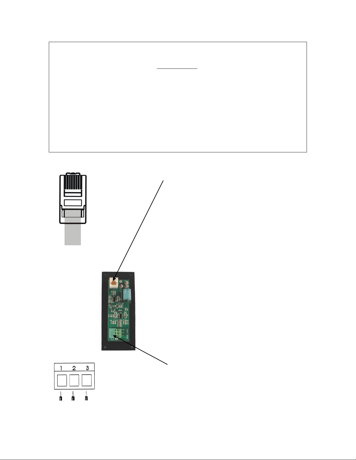
system is on. On the backside of the BLU-CP is
a single RJ-45 Cat5e connector for connecting
the module to the DSP, and a 3-pin Euro-block
IMPORTANT: CAT5 wiring for the RJ-45 connector needs to be
crimped to TIA/EIA 568B Standards (see below) on both ends of the cable.
You must crimp and test the wiring with an approved CAT5 568A/B
tester before connecting any cable between the BLU-CP and either a
BLU-CIF or BLU-IF Interface unit. Failure to crimp w iring to the correct
standard could possibly lead to component damage.
CAUTION: If th e BLU-C P is b ei ng installed in a remodel, check the
width of the op ening in the pedes tal for proper clearance of the r ibbon cable.
You should not crimp or crush the ribbon cable during the install. If the
opening in the pedestal is too narrow, you can ei ther chisel out m or e
clea r ance or mou nt the BLU-CP up using the enclosed nylon standoffs.
Page 2
J1 RJ-45 Pinouts
1 8
Pulpit Up/Dwn – 3-Pin Euro Blo c k
3. GND (C)
Up Down Gnd
EIA/TIA568B
1. White-Orange
2. Orange
3. White-Green
4. Blue
5. White-Blue
6. Green
7. White-Brown
8. Brown
1. Power Button (Logic Input)
2. Volume (Logic Input)
3. Ref Voltage (+4.3V)
4. +24V
5. VCC +5V
6. Power Button LED (Logic Output)
(Key on bottom)
7. SIG GND (C)
8. PWR GND (C)
1. Up
2. Down
 Loading...