

Page 1
BLU- CIF2 Interface Board
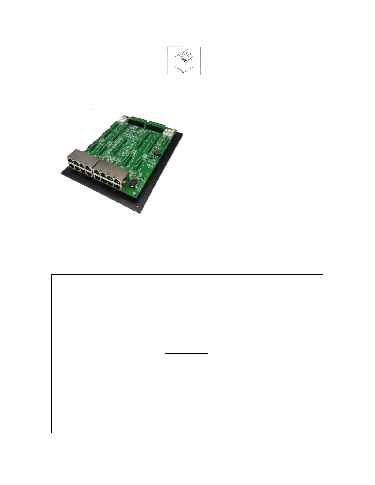
The BLU-CIF2 Interface Board
simplifies the wiring of all of the BLU
products to two BSS Audio London
Series Digital Signal Processors. It
allows for Cat5e wiring termination,
as well as, termination to 3.5mm
euro-style blocks. The BLU-CIF2
accommodates connections for two
BLU-CC, two BLU-CP, two BLUCS, up to five BLU-IR, or up to seven
BLU-SV / BLU-SV8 plus Emtech
MSC-C modules for providing audio
in overflow areas. It is designed for
BLU-CIF2 Cat5e Wiring Instructions
mounting on the back door of a 19”
rack.
IMPORTANT: IF you are using CAT5e wiring termination with the
BLU-CIF2, then the RJ-45 connectors need to be crimped to TIA/EIA 568B
Standards (see below) on both ends of the cable. You must crimp and test
the wiring with an approved CAT5 568A/B tester before connecting any
cable between the BLU Products and the BLU-CIF2 Interface Board.
Failure to crimp wiring to the correct standard could possibly lead to
component damage.
EIA/TIA568B
1. White-Orange
2. Orange
3. White-Green
4. Blue
5. White-Blue
6. Green
7. White-Brown
8. Brown
Page 2
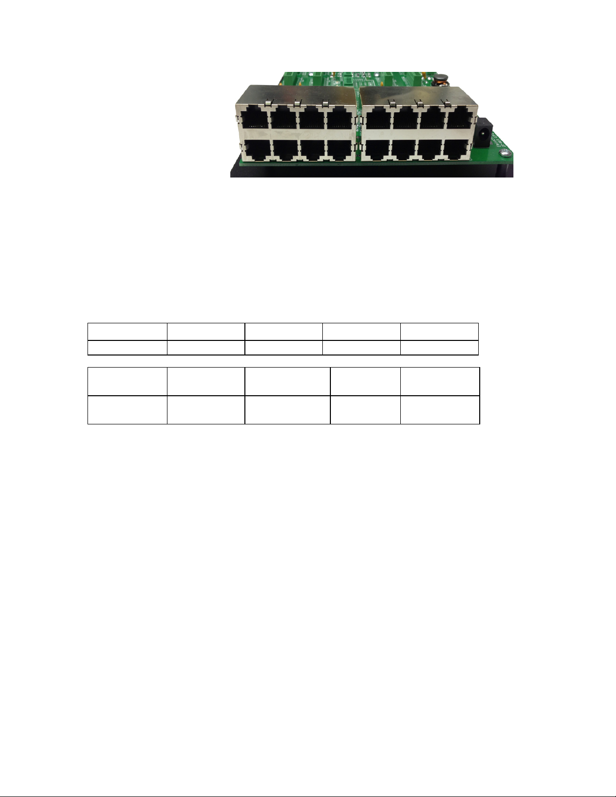
On the left side of the
BLU-CIF2 Interface
Board are two 2 X 4
blocks of RJ-45
connectors for
terminating the BLU
products via Cat5e
wiring. The BLU
products connect in
this order (left to
right), starting with
Block 1:
BLOCK 1 BLOCK 2
BLU-CIF RJ-45 CONNECTIONS
TOP ROW
BTTM ROW
TOP ROW
BTTM ROW
BLU-CP1 BLU-CC1A BLU-SV2 BLU-IR2
BLU-CS/SV1 BLU-CC1B BLU-IR1 BLU-IR3
BLU-IR4 BLU-CP2 BLU-SV4 BLU-
CC2A/SV5
BLU-IR5 BLU-CS2/SV3 BLU-SV7 BLU-
CC2B/SV6
BLOCK 1
BLOCK 2
IMPORTANT: If you use the RJ-45 blocks for connecting the BLUCC, BLU-CP, BLU-CS, BLU-IR and BLU-SV(8) modules, then do not
use any of the 3.5mm euro-style connectors for these accessories. If you
are using the BLU-IR Infrared Sensors for combining audio in overflow
areas, then you have a choice to use either the RJ-45 connections in their
blocks or the 3.5mm euro-style connectors. Wiring the BLU-IR Infrared
Sensors into the 3.5mm connectors will be covered later on in this
document.
A legend for the BLU-CIF2 RJ-45 connections has been silkscreened on the
Interface Board next to the corresponding block of connectors.
BLU-CIF2 3.5mm Euro-block Wiring Instructions
The 3.5mm euro-block connectors have been provided for easy installation
of the BSS Audio equipment into older buildings with existing analog
wiring. Connectors for the BLU-CC, BLU-CP, BLU-CS and BLU-SV have
2
Page 3
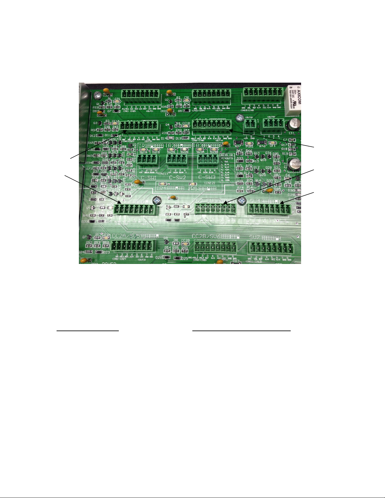
8-pins, and are located behind the RJ-45 blocks on the top half of the board
for DSP1, and on the bottom half of the board for DSP2 .
BLU-CC1A
BLU-CP2
BLU-CP1 BLU-CS/SV1 BLU-SV2
BLU-CC1B
BLU-CS2/SV3
BLU-SV4
BLU-CC2A/SV5 BLU-CC2B/SV6 BLU-SV7
The legends for identifying and wiring these euro-style connectors have all
been silkscreened on the CIF2 Board at the top and bottom side of each
connector. The pin-outs for each connector are listed below:
BLU-CP1 & CP2
1. Power Button (IN1) 1. Power Button (IN3)
2. Volume (IN2) 2. Volume (IN4)
3. VCC 3. Ref
4. +24V 4. N/A
5. Ref 5. VCC
6. LED (OUT1) 6. LED (OUT2)
7. GND 7. GND
8. GND 8. GND
BLU-CS1/SV1 & CS2/SV3
3
Page 4

BLU-CC1A & CC2A/SV5 BLU-CC1B & CC2B/SV6
1. Power Button (IN5) 1. Volume (IN6)
2. Volume (IN7) 2. Volume (IN8)
3. Ref 3. Ref
4. N/A 4. N/A
5. VCC 5. N/A (CC1B) or VCC (CC2B/SV6)
6. LED (OUT3) 6. LED (OUT4)
7. GND 7. N/A
8. GND 8. N/A
BLU-SV2 & SV4
1. SRC (IN10) 1. SRC (IN11)
2. Volume (IN9) 2. Volume (IN12)
3. Ref 3. Ref
4. N/A 4. N/A
5. VCC 5. VCC
6. N/A 6. N/A
7. GND 7. GND
8. GND 8. GND
BLU-SV7
A remote control can be used for controlling the volume of the various
microphone inputs in the cultural hall. When wiring for a remote application
wire to IN5 thru IN9, Ref and GND on CC1A, CC1B and SV2.
BLU-CIF2 / MSC-C Wiring Instructions
Some existing buildings already use Emtech
MSC-C modules to provide chapel audio for the
cultural hall and overflow areas. The BLU-CIF2
is designed to allow these existing modules to
interface with the BSS Audio DSP. Located
through the middle section of the CIF Board are
three 4-pin euro-style connectors. Each
connector has identification and wiring
designations silkscreened below it.
4
Page 5
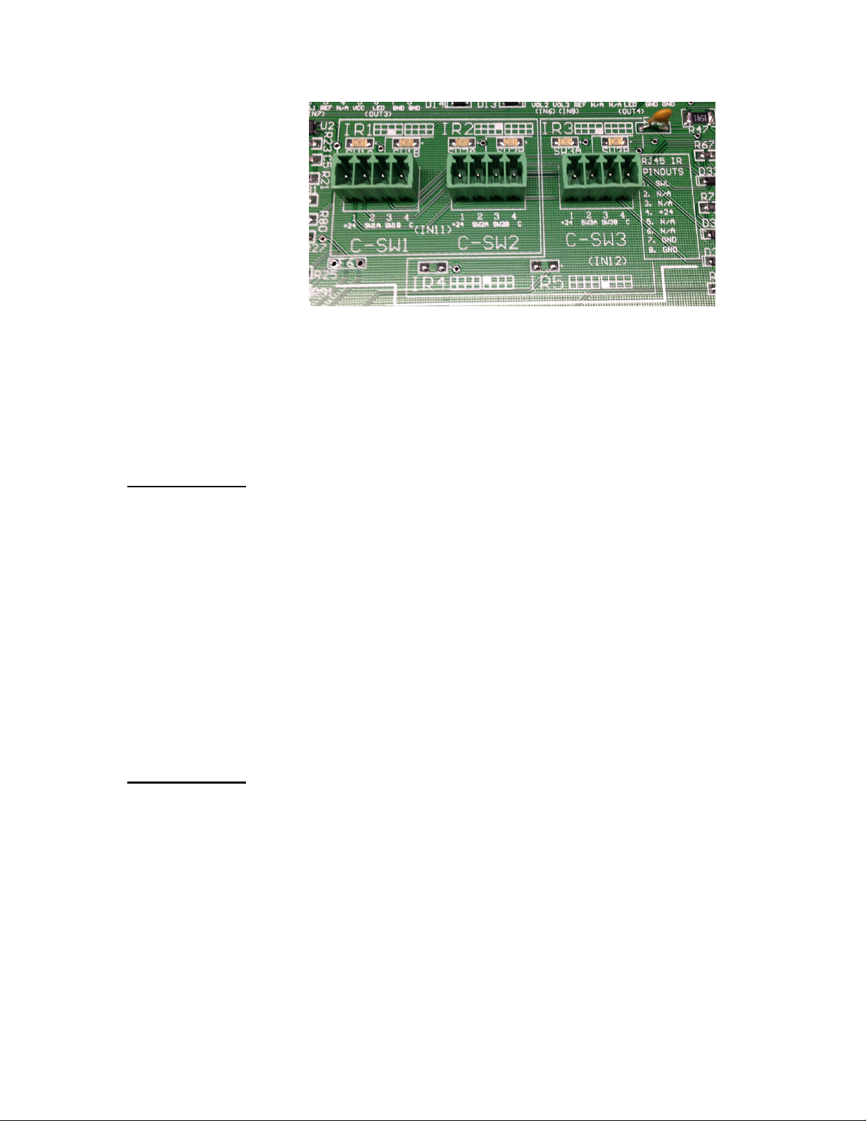
There are no switches associated with the C switch connectors on the new
version of CIF2 board. IN11 and IN12 are bit encoded with 4 bits each. CSW1 and C-SW2 map to IN11, and C-SW3 and IR4-5 map to IN12. When
either a C switch or IR get wired to the CIF board, the device will be
automatically detected. The pin-outs on the C switch connectors are:
C-SW1 thru 3
1. +24V
2. SW1
3. SW2
4. Common
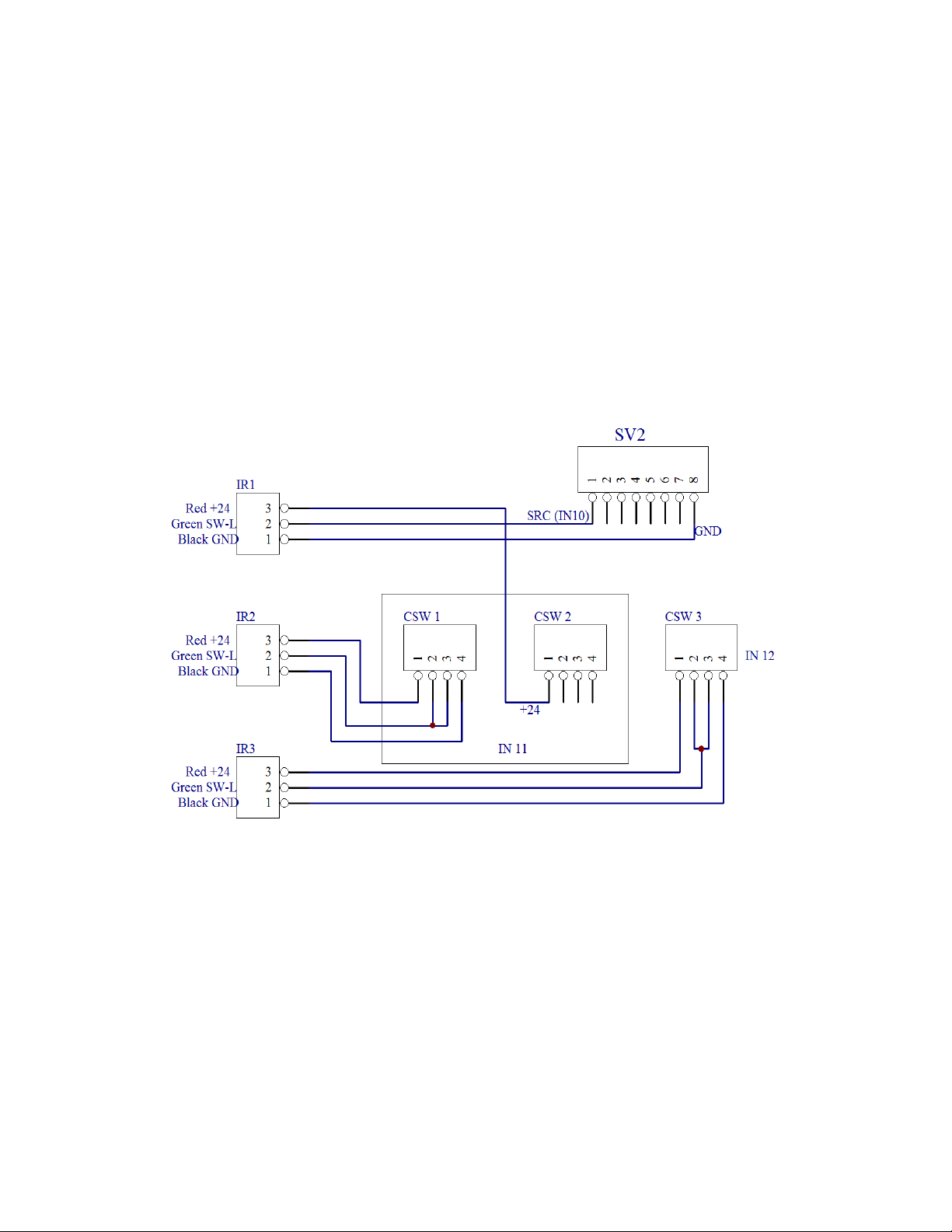
USING the C-SW INPUTS WITH BLU-IR INFRARED SENSORS
The BLU-IR Infrared Sensors can be wired to the 4-pin C-Switch euro-style
connectors. Wire each IR sensor to its’ corresponding 4-pin connector using
this pin-out:
C-SW1 thru 3
1. Red
2. Green
3. N/A
4. Black
5
Page 6

BLU-CIF2 PWR RELAY & OF RELAY Wiring Instructions
p
There are four separate relay
connectors on the right side of the
CIF2 board. The 2-pin PWR_1 &
PWR_2 connections are used to
power on external equipment. This
connection will supply +24VDC @
100mA on the “+24” pin when logic
out
ut 6 on the DSP is triggered.
The voltage from the +24 pin is typically connected to an external power
relay coil, which will then switch 120VAC on to the external equipment.
The PWR RELAY output is thermo-fuse protected, so it will stop supplying
power when the +24 pin exceeds 100mA. The circuit will reset
automatically once the load is disconnected.
The 4-pin OF_1 & OF_2 overflow relay connections are 2-pole “dry
contacts” that are normally open. These contacts will close connecting the
“+” (pin 1) to the “+” (pin 3), and the “-“ (pin 2) to the “-“ (pin 4), when
output port 5 on the DSP is triggered. This is typically used to switch
speaker level signals, so an overflow room can be fed directly from an
amplifier without needing its own dedicated amplifier channel.
Connecting the BLU-CIF2 to the BSS Audio London Series DSP
The BLU-CIF2 ships with four pre-fabricated 12-conductor cables. Each
cable has 3.5mm connectors on both ends. On one end, the 3.5mm
connectors are color-coded green and black, so they match up with either the
Control Port 1 for DSP 1 & Control Port 2 for DSP 2 (Black) connector or
the Logic Inputs (Green) connectors for DSP1 & DSP2 on the far right side
of the CIF2 Board.
Control Inputs Connector
Logic Outputs Connector
6
Page 7

Control Inputs connector mates with the cable
with Control_Port1 (Black) connector.
Logic Outputs connector mates with the cable
with Logic Inputs (Green) connector.
The 3.5mm connectors on the opposite end of each cable are orange. They
match the color of the mating connector on the back of the DSP and are
labeled “top” and “bottom”, so make sure that the cables are connected
correctly on the DSP side. Another way to remember : Black on the
board goes to the top connection on the DSP, and Green on the board
goes to the bottom connection on the DSP. Make sure that the cables
are not crossed – DSP1 Control & Logic go to the first DSP and DSP2
Control & Logic go to the second DSP.
BLU-CIF2 Power
Power Jack
The power jack for the BLU-CIF2 is located on
the bottom left side of the board; below the RJ45 blocks. The BLU-CIF2 is shipped with a
universal desktop power supply that plugs into
the power jack, and supplies it with 24VDC @
1.67A. The power cord on the supply plugs into
a standard 120VAC outlet.
OLDER ACCESSORIES & THE NEW CIF2 BOARD
When using the new BLU-CIF2 board with older versions of
the BLU-CC, BLU-IR or the MSC-C switches there will be some additional
7
Page 8
wiring that must be done on the new BLU-CIF2 board for these to work
properly with the old template. No additional wiring needs to be done when
using the older versions of the BLU-CP and BLU-CS with the new
BLUCIF2 board. When using the new BLU-CC2 with the new BLU-CIF2
board, new templates are required but not additional wiring. Contact BSS
Audio for new templates.
BLU-IR with new BLU-CIF2 using old template:
8
Page 9

MSC-C Switches with new BLU-CIF2 using old template:
9
Page 10

Old BLU-CC with new BLU-CIF2 using old template
10
 Loading...