

Page 1

BTGPS II Trine
GPS Receiver
CRUX_LOG Utility Manual
0
Page 2

Table of Content
1.Connecting to Trine 2
2.Function description 6
2.1 GPS status 6
2.2 Position 6
2.3 Message 7
2.4 SBAS 7
2.5 Trigger 8
2.6 Record 9
2.7 Download 10
2.8 The About 11
3.Advance 12
3.1 GPS positioning condition 12
3-2. Accumulated Value 12
3-3. Changed Value 12
3-4. Threshold Value 13
3-5. Stall case 13
3-6. Turn All Trigger Off, The Log ID and DGPS set remained 13
3-7. Reset Data Logger Trigger Setting to Factory 13
4.Appendix 14
4.1 The Data format of Record 14
4.2 The Data Format of Download 14
1
Page 3
1. Connecting to Trine
1. Before using CRUX_LOG utility , please be sure to open the Trine and the Bluetooth
function is enabled in your PDA.
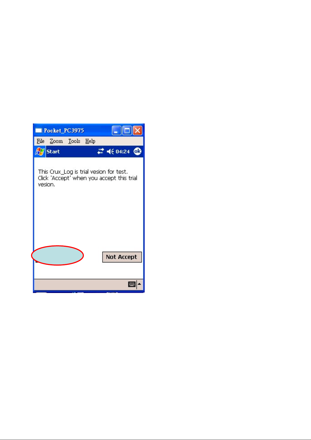
2. Click the CRUX_LOG icon to open it.
3. Click “Accept”, as Figure 1.
Figure 1
2
Page 4
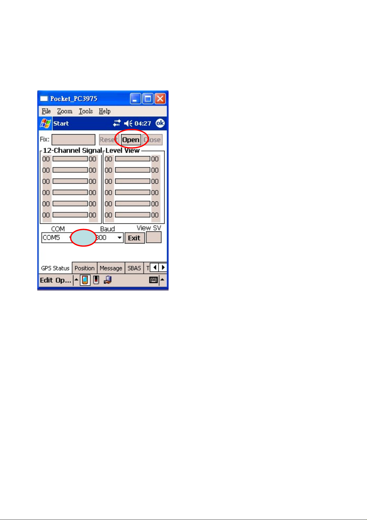
4. Click “BT”, as “a” part shown in Figure 2, to auto-select COM port number
connecting to the BT device.
5. Click “Open”, as “b” part shown in Figure 2, to search all the BT devices.
b
Figure 2
a
3
Page 5
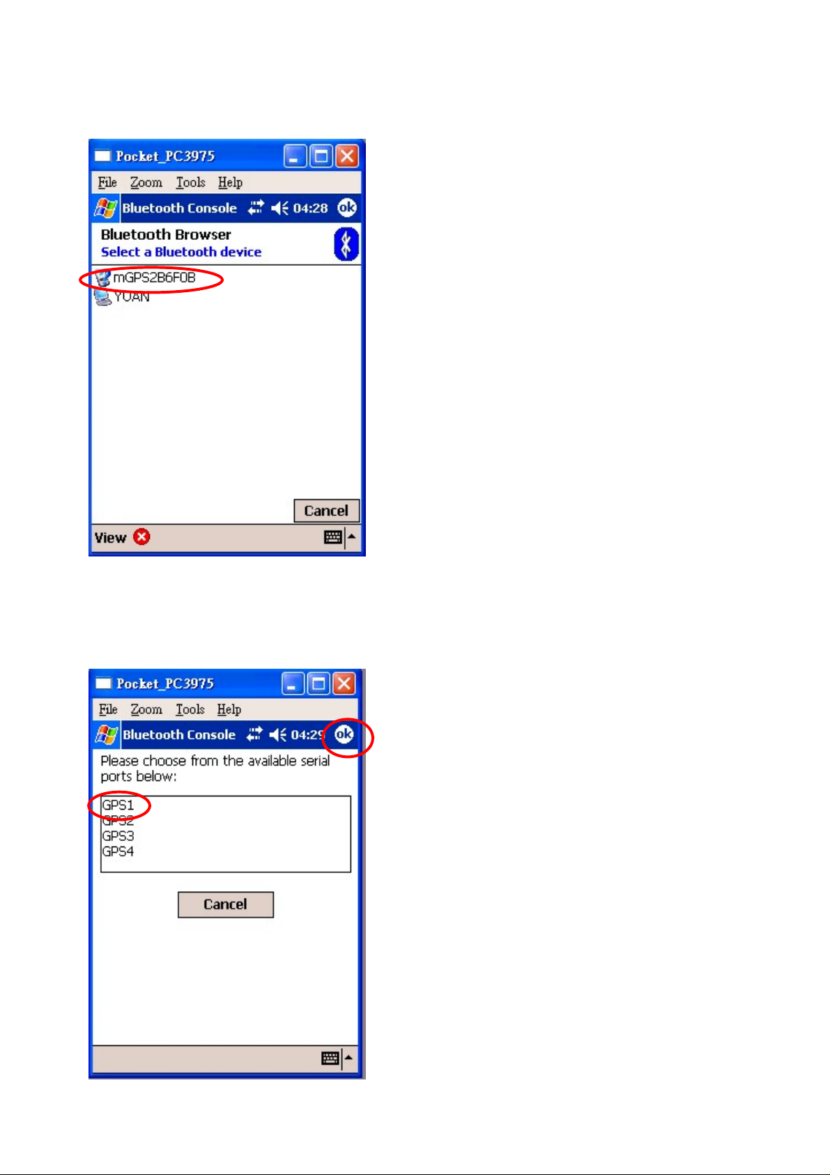
6. After searching described in step 4, the window will show as Figure 3, and then
select Trine, marked in Figure 3.
Figure 3
7. Select a port to connect Trine, shown as Figure 4, and click ok.
b
a
Figure 4
4
Page 6

8. The successful setting is shown as Figure 5.
Figure 5
5
Page 7

2. Function Description
2.1 GPS status
Fix: The fix status, No, 2D or 3D; plus DGPS.
Reset: Cold Start the Trine.
Open: Connect Trine.
Close: Disconnect Trine.
Exit: Exit this program.
View SV: The No. of the Visible Satellites.
12-Channel Signal-Level View: The Signal Level in
dB-Hz of each GPS channel.
2.2 Position
Position: The Latitude and Longitude.
GPS Time: UTC Date and Time.
DOP & Speed:
Fix: The Fix Status, No,2D or 3D;plus DGPS.
PDOP: Position Dilution of Precision.
HDOP: Horizontal Dilution of Precision.
VDOP: Vertical Dilution of Precision.
6
Page 8

2.3 Message
In this page the window displays the NMEA
messages from Trine.
Function Buttons:
Run: Display messages.
Stop: Stop displaying messages.
2.4 SBAS
SBAS Channel setting:
OFF: Disable SBAS channels.
AUTO: Trine auto searches available SBAS
satellites and uses it for correction.
PRN120(EGNOS): Use PRN120 only.
PRN131(EGNOS): Use PRN131 only.
PRN122(WAAS): Use PRN122 only.
PRN134(WAAS): Use PRN134 only.
Manual Set:
Key in PRN No. desired to be used. After setting
the SBAS Channels, Click the “Apply” button to
send the command to Trine.
SBAS Setting: Show the current Trine SBAS
Channel setting.
Command Status: Shows the Command Proceed.
7
Page 9

2.5 Trigger
There are defined levels for triggering that is used to record the data.
Kinds of Trigger: The defined triggering conditions.
Setting Value: This field shows the parameters according to the trigger conditions.
Log ID: Set an ID to Trine, and “write” to update the Trine ID. The default ID is 0.
After choosing the trigger condition from “Kinds of Trigger” and giving the
“setting value”, please click “Apply” to commit the setting. The sliding window
below “Setting Value” displays the configuration of the current T rigger condition.
Note:
When used T rigger Function, the other functions will be disabled shortly until the
“Apply” is available.
For more information, please reference Advance section.
8
Page 10

2.6 Record
This option can be set to “Get Record Number” or “Dump Record Data”, please reference to the
Appendix section for more details.
The action is composed of the “Operate” options and parameters in the “Range”.
If the “Operate” is set to “Get Record Number”, then the meanings of parameters in the
Range is defined as follows:
Total: Read all the number of data logs.
Before: Read the num ber of data logs before the give n Date1 and Time1.
After: Read the number of data logs after the given Date1 and Time1.
Between: Read the number of data logs between the given Date1/Time1 and Date2/Time.
If the “Operate” is set to “Dump Record Data”, then the meanings of parameters in the Range
is defined as follows:
Total: Read the data logs according to the given Begin and End number.
Before: Read the data logs before the given Date1 and Time1.
After: Read the data logs after the given Date1 and Time1.
Between: Read the data logs between the given Date1/Time1 and Date2/Time2.
After choosing one of the configurations, please click “ Apply” button to do the action and the
result will be displa yed in the “ Status” field and t he field below t he “Status” if “Dump Record
Data” is set.
Note: Please DO NOT dump too much data that will cause the errors by lack of memory.
9
Page 11

2.7 Download
This option is used to save data log in the \\My_Device\Trine_Data_Log, as for the data format,
please reference to the appendix section for more details.
FileName: The filename to be saved.
Total Rec Num: The current log number.
Set Param region can be set with the given parameters:
By:
All Data: Download the all data logs.
Sequence no.: Download the logs from the given “ Begin” value to the given “End” value.
Before the date: Download the logs before the given date1 and time1.
After the data: Download the logs after the given date1 and time1.
Between the data: Download the logs between the given data1, time1 and the given date2,
time2.
The date1, date2 format is set as “yymmdd”, and the time1, time2 format is set as “hhmmss”.
Note:
Please BE SURE that the download button is enabled to before using this option.
10
Page 12

2.8 The About
a
b
The about window shows the information of
a. software version
b. firmware version of Trine.
11
Page 13

3.Advance
Trigger Setting for Data Log Read/Write
3.1 GPS positioning condition
3.1.1. select “Positioning Condition(160,3)”
3.1.2. Set “Fix Status” , “HDOP”
3.1.3. click “Apply" Button
P.S.
Fix Status:0:Not Set ,1:Set Fix status change trigger.
HDOP:0:Not Set , 0.1 - 25.5 HDOP change trigger set.
3-2. Accumulated Value
3-2-1. select “Accumulated Condition(160,4)”
3-2-2. Set “Elapse Time” , “Movement”
3-2-3. click “Apply" Button
P.S.
Elapse Time:0:Not Set , 1 – 65535 seconds set.
Movement:0:Not Set , 1 – 65535 meters set.
3-3. Changed Value
3-3-1. select “Changed Value(160,5)”
3-3-2. Set “COG” , “Velocity” , “Altitude”
3-3-3. click “Apply" Button
P.S.
COG;Heading Changed:
0:Not Set , 1 – 255 degrees set.
Velocity;Velocity Changed:
0:Not Set , 1 – 255% set.
Altitude;Altitude Changed:
0:Not Set , 1 – 255 meters set.
12
Page 14

3-4. Threshold Value
3-4-1. select “Threshold Value(160,6)”
3-4-2. Set “Velocity” , “Altitude”
3-4-3. click “Apply" Button
P.S.
Velocity;Velocity Threshold:
0:Not Set , 0.1 – 6553.5 Km/hr set.
Altitude;Altitude Threshold:
0:Not Set , 1 – 65535 meters set.
3-5. Stall case
3-5-1. select “Stall case(160,7)”
3-5-2. Set “Velocity” , “Elapse Time”
3-5-3. click “Apply" Button
P.S.
Velocity;Stall Velocity Threshold Value:
0:Not Set , 0.1 – 6553.5 Km/hr set.
Elapse Time;Stall Elapse Time:
0:Not Set , 1 - 255 secords set.
3-6. Turn All Trigger Off, The Log ID and DGPS set remained
3-6-1. select “Turn All Trigger Off(160,8)”
3-6-2. click “Apply" Button
3-7. Reset Data Logger Trigger Setting to Factory
Default Setting,Logger ID=0,No Trigger Set.
3-7-1. select “Reset Data Logger(160,9)”
3-7-2. click “Apply" Button
13
Page 15

4.Appendix
4.1 The Data format of Record
$CmdID,Sub_CmdID,rec_no,yymmdd,hhmmss,fix,dop,DDMM.mmmm,DDDMM.mmmm,MM.
m,cog,vel*CKSUM
CmdID: Command ID
Sub_CmdID: sub-command ID
Rec_no:” log number
yymmdd,hhmmss: UTC Time
fix: satellites fix status.
dop: HDOP
DDMM.mmmm: Latitude
DDDMM.mmmm: Longitude
MM.m: Altitude
cog:Course Over Ground
vel: velocity
4.2 The Data Format of Download
Record-Length=20 bytes; Data are in little endian.(Lower byte=LSB)
14
 Loading...