


FCC Part 24
Transmitter Certification
Test Report
FCC ID: DNY0B2SCELL1900
FCC Rule Part: CFR 47 Part 24 Subpart E
ACS Report Number: 05-0272-24E
Manufacturer: EMS Wireless
Equipment Type: PCS Band Bi-Directional Amplifier
Model: SelectaCell-19-S
5015 B.U. Bowman Drive Buford, GA 30518 USA Voice: 770-831-8048 Fax: 770-831-8598
Operators Manual
®
SelectaCell
OPERATOR’S MANUAL
(Preliminary)
1900 MHz BAND-SELECT INDOOR REPEATER
-19S
2850 Colonnades Court
Norcross, GA 30071 U. S. A.
Tel: +770.582.0555
Fax: +770.729.0075
IM609873-1 Rev. 01
07/11/05


Handling the SelectaCell®
1. Use ESD precautions when dealing with the modules within the SelectaCell™ so that units are not
damaged.
2. Opening the unit voids warranty.
3. Disconnecting any component within the SelectaCell™ when powered can damage or destroy the
equipment and will void the warranty.
1.0 Description
The SelectaCell® repeater, is a PCS band, band selective bi-directional amplifier with integrated donor
and server antennas. The unit is designed to provide enhanced RF coverage for wireless systems in
small facilities. Usage includes providing coverage in retail stores, offices, warehouses, restaurants,
homes, etc.
The SelectaCell®
supports all 1900 MHz system protocols including CDMA, GSM/PCS1900 and
TDMA and a single model will cover PCS licensed 5MHz or 15MHz bands/sub-bands A through F.
The SelectaCell®
features easy set-up, lightweight, compact enclosure with internal antennas, local
alarming, excellent electrical specifications, high reliability and cost effective pricing.
2.0 Functionality
The SelectaCell® is capable of automatically adjusting its own signal gain levels up to the maximum
output power levels. SelectaCell® detects the downlink output power and adjusts the level for +12
dBm EIRP composite output power and continues to monitor and reset the gain as required for proper
system performance. For example, when CDMA protocol is being amplified, there could be an error
in set up initially resulting from only pilot sync, and paging Walsh codes being present on the RF
carrier. The SelectaCell® will reduce the system gain until no signal is received that will exceed the
output power setting. This prevents the SelectaCell® from setting up to a higher power level than
actually desired if all of the Walsh codes were present. The gain does not continually change to
maintain an output power of 0 dBm (AGC) since this would defeat the benefits of power control in the
service providers system.
3.0 Alarming
Alarming monitoring is accomplished in the SelectaCell® by the microprocessor, which will detect a
failure in gain or a system oscillation. This is indicated to the user by the LCD display and by
application software via the USB interface.
IM609873-1 Rev. 01
07/11/05
SelectaCellTM Operator’s Manual – Preliminary EMS Wireless
4.0 Primary Power
The SelectaCell® operates on 7.5 VDC input power @ 0.7 Amp. This unit is supplied with a regulated
wall mount power supply, which is UL, and CSA listed and will operate on AC input voltage of 90-240
VAC.
5.0 Donor/Server Antenna
Internal donor and server antennas have 13 dB and 10dB gain, respectively. The donor antenna must
be orientated to point in the direction of the Service Providers cell site location, but does not necessarily
have to point exactly at the cell site. The indicators will provide a reference of the strongest RF power
strength when the antenna is located in the optimum location.
6.0 Installation:
Note 1: The user is cautioned that modification or changes to this device not expressly approved by the
party responsible for compliance could void the user’s authority to operate this equipment.
Note 2: Manufacturer’s rated composite output power, individual channel power will vary depending on
the number of channels and distance from each cell site being received
Note 3: This device complies with Part 15 of the FCC Rules. Operation is subject to the condition that
this device does not cause harmful interference.
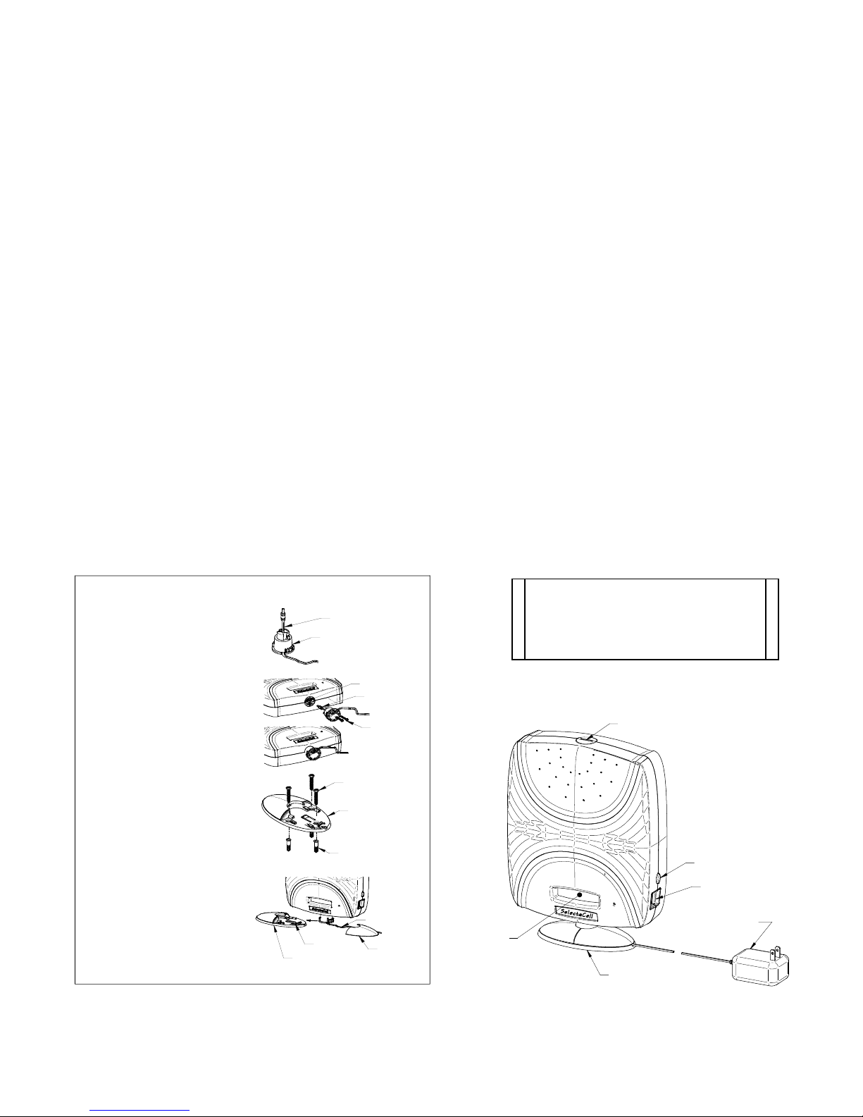
Step 1: Feed Power Cord through
Mounting Adap te r
SelectaCell®
Mounting Instructions
Power Cord
Mou nting A d a pte r
Note: Assemble foot support on unit
to check setup prior to installing and
firming attaching with bottom screws to
Step 2: A tta ch P o w e r P lug to P o w er
Jack on S e lecta C ell® a nd
attach Mou n ting A da p ter
using 2 Screws provided
Power Jack
Power Plug
Screw
Plug
Step 3: A tta ch M o u ntin g B a se to
suitable surface u sing
Screws and Anchors as
necessa ry
Screw
Mo un ting Ba se
Step 4 : S lide S e lecta C e ll® w ith
Mo un ting A d ap te r on to
Mo un tin g B a se an d rou te
Po w e r C ord throu g h
Ch a nn e l in Mo u ntin g B a se .
Slide C o v er on to M ou n ting
Ba se .
Mounting Base
Anchor
Channel
Power Cord
Cover
Switch
USB Port
Power Supply
Display
Mounting Base
EMS Wireless SelectaCell®-19S Manual
Confidential and Proprietary Information
IM609873-1 Rev 01
07/11/05
4
SelectaCellTM Operator’s Manual – Preliminary EMS Wireless
7.0 Introduction
SelectaCell® setup is automated for easy installation. This section will provide the basic steps to
performing the unit’s setup and installation.
SelectaCell® is designed to automatically optimize set up and will improve performance in most
applications as long as a signal can be received at a window. Actual area of coverage that will be
improved will vary depending on the signal level received and blockage.
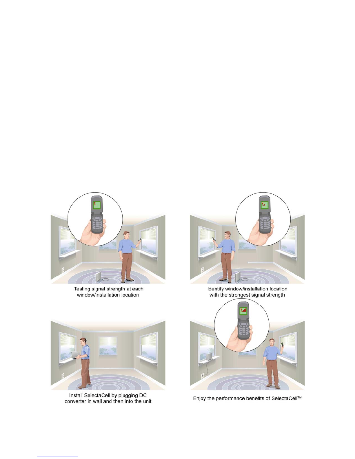
Placement of the unit
The SelectaCell® unit should be located in a window where the user’s service provider has enough
coverage to initiate a call. For best results, the user should select the window with the greatest signal
strength. This can be determined by observing the number of bars on the user’s cell phone:
EMS Wireless SelectaCell®-19S Manual
Confidential and Proprietary Information
IM609873-1 Rev 01
07/11/05
5

SelectaCellTM Operator’s Manual – Preliminary EMS Wireless
8.0 Setup Instructions
There are two setup methods that may be used to select and set a 5 or 15 MHz frequency band on
SelectaCell™;
a. Manual Push Button
b. Computer setup through the USB ports
Setup Instructions using the Manual Push Button
SelectaCell-19S must be set up to the proper assigned frequency band before completing installation.
After band selection, the unit will enter the downlink monitor state for determining optimum
positioning of the unit. Once this process is complete, the unit will power up in the assigned band
(displayed in preamble) each time the unit is power cycled.
LCD Preamble Message:
[SelectaCell-19S]
EMS Wireless
All rights reserved
V1.0 Date (Software version and date)
Band A Assigned band
Test for signal strength at each window to identify the location with the greatest signal strength.
1. Using a subscriber unit (cell phone) and monitoring the signal strength indicators (number
of bars displayed on the phone), check each window location. The window location that
has the most displayed bars should be the location selected. Place the unit on the
windowsill or on a counter or nearby table top or other convenient location with the LCD
display facing indoors.
Note: Please do not locate the SelectaCell in an area that can be obstructed either in front or behind,
e.g. bookshelf, cornered areas, behind closed blinds or plants
.
A. Select PCS Band of Operation Manually
Select by:
1. Depress and hold button (which is located just above the USB port) about 3 seconds while
connecting AC power to the unit.
2. Release button during the preamble messages being displayed on the LCD screen.
3. Current band assignment setup on the unit will display, blinking on/off (e.g. Band A)
4. Each time button is pressed, it will now advance the unit to the next band in 5 MHz
segments. Continue pressing the button until the desired band either 15 MHz or 5 MHz
band segment is selected. If desired band is already displayed, proceed to next step.
EMS Wireless SelectaCell®-19S Manual
Confidential and Proprietary Information
IM609873-1 Rev 01
07/11/05
6

SelectaCellTM Operator’s Manual – Preliminary EMS Wireless
5. Once the desired band is selected, hold down the button for 3 seconds, this will now
program the unit for the selected band and enter the unit into downlink monitor mode.
6. In downlink monitor mode only the downlink signal is being amplified. The LCD display
will have bars on the left side indicating downlink signal and bars on the right side
indicating downlink gain.
7. Position the unit to achieve maximum signal strength by rotating the unit slightly while observing
the bars for maximum signal strength.
Signal Strength Indicator
(2dB steps)
0 to 8 Bars on Graph
1. Right row is gain setting, full gain is 8 bars
2. Left row is signal strength, up to 8 bars
Gain Setting Indicator
(2dB steps)
0 to 8 Bars on Graph
8. Once unit position is complete, hard power recycle by manually disconnecting and reconnecting AC
power. This will allow the unit to automatically set up on the new band assignment.
Important: This step must be performed to save the selected band.
B. SelectaCell Setup Instruction through USB
Setup instructions via the USB port and requiring a computer connection to the SelectaCell®
Before configuring the unit over USB, the application software must be loaded into the computer from
the SelectaCell Application Software CD included.
1. Insert CD and save files to a folder
2. Go to the saved folder
· Install dotnet by running “dotnetfx.exe” file (double click)
· Follow the set up procedure displayed
3. Next Open the SelectaCell® USB App Setup folder
EMS Wireless SelectaCell®-19S Manual
Confidential and Proprietary Information
IM609873-1 Rev 01
07/11/05
7

SelectaCellTM Operator’s Manual – Preliminary EMS Wireless
· install the.........."Setup.exe" (double click)
· Follow the set up procedure displayed
4. Connect a USB type “A” Male to “A” Male cable into computer USB port and the
SelectaCell®
Note: The SelectaCell® AC power should not be plugged in at this time.
a. A pop-up window should appear on the computer screen advising that new USB
hardware is present and the driver is being installed.
b. If driver is requested, locate it in a separate directory on the CD. Browse to /drivers for
"SiF32x_USB.inf".
5. Locate the “Select-A-Cell” program from your Start menu
a. Open the file (double click). Without the SelectaCell®
connected, a USB timeout
condition will appear, which is a blinking red indicator on the right side of the screen.
Once the installation software is loaded, proceed to the next step.
6. At this time, using a 7.5Vdc power supply, and apply power to the SelectaCell®.
7. After applying power to the connected SelectaCell®
, the USB timeout indication will
automatically clear and the indicator should switch from flashing red to solid green on the
Identity screen.
a. Select Get and this screen will also display the Firmware Revision, Model, Serial
Number, and PCB Serial Number. (See Screen A.)
b. Select Save to store this information
8. From the top of the screen location select the Frequency tab and now the SelectaCell®
frequency may be viewed (See Screen B). The following frequency bands may be selected :
Band Frequency
A – 1850-1865 and 1930-1945
A1- 1850-1855 and 1930-1935
A2- 1855-1860 and 1935-1940
A3- 1860-1865 and 1940-1945
B - 1870-1885 and 1950-1965
B1- 1870-1875 and 1950-1955
B2- 1875-1880 and 1955-1960
B3- 1880-1885 and 1960-1965
C - 1895-1910 and 1975-1990
C4- 1895-1900 and 1975-1980
C5- 1900-1905 and 1980-1985
C6- 1905-1910 and 1985-1990
D - 1865-1870 and 1945-1950
E - 1885-1890 and 1965-1970
F - 1890-1895 and 1970-1975
EMS Wireless SelectaCell®-19S Manual
Confidential and Proprietary Information
IM609873-1 Rev 01
07/11/05
8

SelectaCellTM Operator’s Manual – Preliminary EMS Wireless
Frequency setting changes are password protected and by pressing Ctrl-Alt-p enter password
as all caps " PASSWORD"
a. Select the “By Band” method of Frequency Selection
i. Select the appropriate PCS band or sub-band with a mouse click. (Single alpha
letter of entire band or alpha numeric segments).
ii. Bandwidth selection of 5 MHz or 15 MHz will display automatically if band is
selected by band but is also used to select frequency band width filter size
entering Center Frequency.
b. After selecting the correct frequency band, save by selecting the “Set” button with a
mouse click to activate and store this information in the SelectaCell®.
c. Next move to the next screen by selecting the top Control tab
i. Press to Restart and view the power and gain. (Screen C) and save all
programmed information
d. “By Center Frequency” method of Frequency Selection
i. Click on and select the appropriate box for By Center Frequency
ii. Select the requested Bandwidth filter size of either 5 MHz or 15 MHz
iii. Input the 4 digit PCS downlink frequency and Uplink the uplink frequency will
appear .
e. Verify input downlink and uplink frequency
f. After selecting the correct frequencies, save by selecting the “Set” button with a mouse
click
g. Next, to activate and store this information in the SelectaCell® move to the next screen
by selecting the top Control tab
i. Press Restart and view the power and gain. (Screen C) and this will save all
programmed information, which will take 15 – 20 seconds to reset
Note: if “Restart” is not activated, the unit will not retain the requested band and will
startup in the previously selected or factory fault band upon a power recycle. .
9. Viewing System Downlink and Uplink RF Power and Gain (Screen C)
a. Select the screen Control tab
b. Activate “Restart” button with a mouse click to view the newly selected frequency
band setup, which will take 30 – 60 seconds to adjust.
c. When the unit LCD displays OK, disconnect the USB cable
Place the unit in a window with the LCD facing desired coverage area, wait a few minutes for
automatic adjustment and now you are up and running.
EMS Wireless SelectaCell®-19S Manual
Confidential and Proprietary Information
IM609873-1 Rev 01
07/11/05
9

SelectaCellTM Operator’s Manual – Preliminary EMS Wireless
Screen Shots Interface Overview Using the USB Connection
The preliminary version of the SelectaCell® application has 3 menu tabs that can be selected from the
top portion of the application.
Screenshots and explanations of the menus are as follows:
Identity Startup Screen
Screen A
Identity screen displays SelectaCell® unit version, Model, Serial and PCB Serial Number plus any error
status indicators. These are stored in non-volatile flash on the SelectaCell® hardware and not in the
application or computer.
EMS Wireless SelectaCell®-19S Manual
Confidential and Proprietary Information
IM609873-1 Rev 01
07/11/05
10

SelectaCellTM Operator’s Manual – Preliminary EMS Wireless
Frequency Screen
Screen B
Indicates frequency / PCS band of operation and also displays error indicators.
Select the frequency tab and select the appropriate PCS band or sub-band with a mouse click. Activate
the “Set” button with a mouse click to setup either by the desired band in the SelectaCell® or input the
center frequency for the downlink and the uplink will automatically display . Activate the “Set”
button with a mouse click to store this band in the SelectaCell®. Note: if “Set” is not activated, the
unit will startup in the previously selected or factory fault band upon a power cycle. .
EMS Wireless SelectaCell®-19S Manual
Confidential and Proprietary Information
IM609873-1 Rev 01
07/11/05
11

SelectaCellTM Operator’s Manual – Preliminary EMS Wireless
Control Screen
Screen C
Displays downlink and uplink output power and gain and is used to restart the SelectaCell® after
selecting a new frequency band.
After selecting the PCS band, in the previous frequency screen, activate “Restart” button with a
mouse click initiate automated setup.
EMS Wireless SelectaCell®-19S Manual
Confidential and Proprietary Information
IM609873-1 Rev 01
07/11/05
12

SelectaCellTM Operator’s Manual – Preliminary EMS Wireless
9.0 Specifications
Downlink Operating Frequency, 1930 to 1990 MHz
Uplink Operating Frequency, 1850 to 1910 MHz
Downlink Transmit Power, +12dBm EIRP
Uplink Transmit Power, +25dBm EIRP
System Gain, 50 to 80 dB
Gain Flatness
Noise Figure
+/− 2 dB
≤ 4 dB
Spurious Output @ Rated Power,
FCC Regulations, Spurious Emissions
Operating Temperature
≤ -13 dBm
0 to +50°C
Power AC to DC External (90-240 VAC) 7.5 VDC @ 7 amp
MTBF 80,000 hours
Automatic System Set Up Upon Power Up
Certifications FCC, UL, CSA
Meets or exceeds the EIA/TIA requirements
for CDMA, TDMA or GSM system protocols.
WARNINGS, CAUTIONS, AND GENERAL NOTES
This product conforms to FCC Part 15, Section 21. Changes or modifications not expressly approved by
Note: This equipment has been tested and found to comply with the limits for a Class B digital device,
the party responsible for compliance could void the user's authority to operate the equipment.
pursuant to part 15 of the FCC rules. These limits are designed to provide reasonable protection
against harmful interference when the equipment is operated in a residential environment. This
equipment generates, uses and can radiate radio frequency energy and, if not installed and used
in accordance with the instructions, may cause harmful interference to radio communications.
However, there is no guarantee that interference will not occur in a particular installation. If this
equipment does cause harmful interference to radio or television reception, which can be
determined by turning the equipment off and on, the user is encouraged to try to correct the
interference by one or more of the following measures:
• Reorient or relocate the receiving antenna.
• Increase the separation between the equipment and receiver
• Connect the equipment into an outlet on a circuit different from that to which the receiver is
connected.
• Consult the dealer or an experienced radio/TV technician for help
In accordance with FCC regulations regarding human exposure to radio frequency energy, this device shall
be installed such that a minimum separation distance of 20cm is maintained between it and general
population.
EMS Wireless SelectaCell®-19S Manual
Confidential and Proprietary Information
IM609873-1 Rev 01
07/11/05
13

SelectaCellTM Operator’s Manual – Preliminary EMS Wireless
This Class B digital apparatus meets all requirements of the Canadian Interference Causing Equipment
Regulations. Operation is subject to the following two conditions: (1) this device may not cause harmful
interference, and (2) this device must accept any interference received, including interference that may
cause undesired operation.
Cet appareillage numérique de la classe B répond à toutes les exigences de l'interférence canadienne
causant des règlements d'équipement.L'opération est sujette aux deux conditions suivantes: (1) ce
dispositif peut ne pas causer l'interférence nocive, et (2) ce dispositif doit accepter n'importe quelle
interférence reçue, y compris l'interférence qui peut causer l'opération peu désirée.
Safety Considerations
When installing or using this product, observe all safety precautions during handling and operation.
WARNING
WARNING calls attention to a procedure or practice, which if ignored, may result in damage to the system
If You Need Help
If you need additional copies of this manual, or have questions about system options, or need help with
Service
Do not attempt to modify or service any part of this product other than in accordance with
When returning a product for service, include the following information: Owner, Model Number,
The EMS Wireless Quality Plan includes product test and inspection operations to verify the
EMS Wireless uses every reasonable precaution to ensure that every device meets published
Failure to comply with the following general safety precautions and with specific precautions described
elsewhere in this manual violates the safety standards of the design, manufacture, and intended use of
this product. EMS Wireless assumes no liability for the customer's failure to comply with these
precautions.
or system component. Do not perform any procedure preceded by a WARNING until described conditions
are fully understood and met.
installation and using of the system, please contact EMS Wireless’ Customer Support.
EMS Wireless Customer Support
2850 Colonnades Court NW, Norcross, GA 30071
+1 770.582.0555 x 5310
email: cs.wireless@ems-t.com
procedures outlined in this Operator's Manual. If the product does not meet its warranted
specifications, or if a problem is encountered that requires service, notify EMS Wireless’
customer support department. Service will be rendered according the EMS Wireless’ warranty
and repair policy. The product shall not be returned without contacting EMS Wireless and
obtaining a return authorization number from the Customer Support department.
Serial Number, Return Authorization Number (obtained in advance from EMS Wireless
Customer Support Department), service required and/or a description of the problem
encountered.
quality and reliability of our products.
electrical, optical, and mechanical specifications prior to shipment. Customers are asked to
advise their incoming inspection, assembly, and test personnel as to the precautions required in
handling and testing ESD sensitive components. Physical damage to the external surfaces voids
warranty.
EMS Wireless SelectaCell®-19S Manual
Confidential and Proprietary Information
IM609873-1 Rev 01
07/11/05
14

SelectaCellTM Operator’s Manual – Preliminary EMS Wireless
These products are covered by the following warranties:
1. General Warranty
EMS Wireless warrants to the original purchaser all standard products sold by EMS
Wireless to be free of defects in material and workmanship for the duration of the
warranty period of one (1) year from date of shipment from EMS Wireless. During the
warranty period, EMS Wireless’ obligation, at our option, is limited to repair or
replacement of any product that EMS Wireless proves to be defective. This warranty
does not apply to any product, which has been subject to alteration, abuse, improper
installation or application, accident, electrical or environmental over-stress, negligence in
use, storage, transportation or handling.
2. Specific Product Warranty Instructions
All EMS Wireless products are manufactured to high quality standards and are
warranted against defects in workmanship, materials and construction, and to no further
extent. Any claim for repair or replacement of a device found to be defective on
incoming inspection by a customer must be made within 30 days of receipt of the
shipment, or within 30 days of discovery of a defect within the warranty period.
This warranty is the only warranty made by EMS Wireless and is in lieu of all other
warranties, expressed or implied, except as to title, and can be amended only by a
written instrument signed by an officer of EMS Wireless. EMS Wireless sales agents or
representatives are not authorized to make commitments on warranty returns.
In the event that it is necessary to return any product against the above warranty, the
following procedure shall be followed:
a. Return authorization shall be received from the EMS Wireless Customer Support
prior to returning any device. Advise the EMS Wireless Customer Support of the
model, serial number, and the discrepancy. The device shall then be forwarded
to EMS Wireless, transportation prepaid. Devices returned freight collect or
without authorization may not be accepted.
b. Prior to repair, EMS Wireless Customer Support will advise the customer of EMS
Wireless test results and will advise the customer of any charges for repair
(usually for customer caused problems or out-of-warranty conditions).
If returned devices meet full specifications and do not require repair, or if non-
warranty repairs are not authorized by the customer, the device may be subject
to a standard evaluation charge. Customer approval for the repair and any
associated costs will be the authority to begin the repair at EMS Wireless.
Customer approval is also necessary for any removal of certain parts, such as
connectors, which may be necessary for EMS Wireless testing or repair.
EMS Wireless SelectaCell®-19S Manual
Confidential and Proprietary Information
IM609873-1 Rev 01
07/11/05
15

SelectaCellTM Operator’s Manual – Preliminary EMS Wireless
c. Repaired products are warranted for the balance of the original warranty period,
or at least 90 days from date of shipment.
3. Limitations of Liabilities
EMS Wireless’ liability on any claim of any kind, including negligence, for any loss or
damage arising from, connected with, or resulting from the purchase order, contract, or
quotation, or from the performance or breach thereof, or from the design, manufacture,
sale, delivery, installation, inspection, operation or use of any equipment covered by or
furnished under this contract, shall in no case exceed the purchase price of the device
which gives rise to the claim.
EXCEPT AS EXPRESSLY PROVIDED HEREIN, EMS WIRELESS MAKES NO
WARRANTY OF ANY KIND, EXPRESSED OR IMPLIED, WITH RESPECT TO ANY
GOODS, PARTS AND SERVICES PROVIDED IN CONNECTION WITH THIS
AGREEMENT INCLUDING, BUT NOT LIMITED TO, THE IMPLIED WARRANTIES OF
MERCHANTABILITY AND FITNESS FOR A PARTICULAR PURPOSE. EMS
WIRELESS SHALL NOT BE LIABLE FOR ANY OTHER DAMAGE INCLUDING, BUT
NOT LIMITED TO, INDIRECT, SPECIAL OR CONSEQUENTIAL DAMAGES ARISING
OUT OF OR IN CONNECTION WITH FURNISHING OF GOODS, PARTS AND
SERVICE HEREUNDER, OR THE PERFORMANCE, USE OF, OR INABILITY TO USE
THE GOODS, PARTS AND SERVICE.
EMS Wireless test reports or data indicating mean-time-to-failure, mean-time-between-
failure, or other reliability data are design guides and are not intended to imply that
individual products or samples of products will achieve the same results. These
numbers are to be used as management and engineering tools, and are not necessarily
indicative of expected field operation. These numbers assume a mature design, good
parts, and no degradation of reliability due to manufacturing procedures and processes.
Handling the SelectaCell™
1. Use ESD precautions when dealing with the modules within the SelectaCell™ so that units are not
damaged.
2. Opening the unit voids warranty.
3. Disconnecting any component within the SelectaCell™ when powered can damage or destroy the
equipment and will void the warranty.
EMS Wireless SelectaCell®-19S Manual
Confidential and Proprietary Information
IM609873-1 Rev 01
07/11/05
16

SelectaCellTM Operator’s Manual – Preliminary EMS Wireless
EMS Wireless SelectaCell®-19S Manual
Confidential and Proprietary Information
IM609873-1 Rev 01
07/11/05
17

SelectaCellTM Operator’s Manual – Preliminary EMS Wireless
EMS Wireless SelectaCell®-19S Manual
Confidential and Proprietary Information
IM609873-1 Rev 01
07/11/05
18

SelectaCellTM Operator’s Manual – Preliminary EMS Wireless
2850 Colonnades Court
Norcross, GA 30071
PH: 770.582.0555
FAX: 770.729.0075
EMS Wireless SelectaCell®-19S Manual
Confidential and Proprietary Information
IM609873-1 Rev 01
07/11/05
19
 Loading...