


Type Acceptance Test Report
Broad Band PCS Transceiver
FCC ID: DNY0A5DATA1900
FCC Rule Part: 24E
ACS Report Number: 03-0096-24TA
Manufacturer: EMS Wireless
Model: DataNex
Installation and Operators Guide
5015 B.U. Bowman Drive Buford, GA 30518 USA Voice: 770-831-8048 Fax: 770-831-8598
EMS Wireless
DataNex™
Data-20 Digital Radio
User Reference Manual
2850 Colonnades Court NW
Norcross, GA 30071
Phone: 770-582-0555
Fax: 770-729-0075

Table of Contents ii
Document Number: Rev: A
Last Saved
NXE1 Manual Dwg # ; Revision Levels:
Section Drawing No: REV Revised /
Reason
Released
Data-20 A SN NEW
DataNex EMS Wireless, DATA-20 Digital Radio

iii Table of Contents
WARNINGS, CAUTIONS, AND GENERAL NOTES
This product conforms to FCC Part 15. Changes or modifications not expressly
approved by the party responsible for compliance could void the user's authority to
operate the equipment.
NOTE: This equipment has been tested and found to comply with the limits for a
Class B digital device, pursuant to Part 15 of the FCC Rules. These limits are
designed to provide reasonable protection against harmful interference in a
residential installation. This equipment generates, uses and can radiate radio
frequency energy and, if not installed and used in accordance with the instructions,
may cause harmful interference to radio communications. However, there is no
guarantee that interference will not occur in a particular installation. If this
equipment does cause harmful interference to radio or television reception, which
can be determined by turning the equipment off and on, the user is encouraged to
try to correct the interference by one or more of the following measures:
• Reorient or relocate the receiving antenna.
• Increase the separation between the equipment and receiver.
• Connect the equipment into an outlet on a circuit different from that to
which the receiver is connected.
• Consult the dealer or an experienced radio/TV technician for help.”
In accordance with FCC regulations regarding human exposure to radiofrequency
energy, this device shall be installed such that a minimum separation distance of 20cm
is maintained between it and general population.
The antennas used for this transmitter must not be co-located or operating in conjunction
with any other antenna or transmitter.
This Class B digital apparatus meets all requirements of the Canadian
Interference Causing Equipment Regulations. Operation is subject to the
following two conditions: (1) this device may not cause harmful interference, and (2)
this device must accept any interference received, including interference that may
cause undesired operation.
Cet appareillage numérique de la classe B répond à toutes les exigences de
l'interférence canadienne causant des règlements d'équipement. L'opération
est sujette aux deux conditions suivantes: (1) ce dispositif peut ne pas causer
l'interférence nocive, et (2) ce dispositif doit accepter n'importe quelle interférence
reçue, y compris l'interférence qui peut causer l'opération peu désirée.
DataNex EMS Wireless, DATA-20 Digital Radio

Table of Contents iv
Table of Contents
1 SYSTEM DESCRIPTION .......................................................................................................................1-1
1.1
Introduction ..................................................................................................................................................... 1-1
1.2 System Features............................................................................................................................................... 1-1
1.3 Typical Configurations.................................................................................................................................... 1-2
1.3.1 Data Rate and Interface ............................................................................................................................. 1-2
1.3.2 Standalone Operation ................................................................................................................................ 1-2
1.3.3 Hot Standby (Protected) Operation............................................................................................................ 1-3
1.4 Regulatory Notices........................................................................................................................................... 1-3
1.5 System Description (QAM)............................................................................................................................. 1-4
1.5.1 Introduction ............................................................................................................................................... 1-4
1.5.2 QAM Modulator/IF Upconverter............................................................................................................... 1-5
1.5.3 RF Upconverter ......................................................................................................................................... 1-6
1.5.4 Power Amplifier (PA) ............................................................................................................................... 1-7
1.5.5 RF Downconverter .................................................................................................................................... 1-7
1.5.6 QAM Demodulator/IF Downconverter ..................................................................................................... 1-8
2 INSTALLATION .....................................................................................................................................2-1
2.1 Unpacking ........................................................................................................................................................ 2-1
2.2 Notices............................................................................................................................................................... 2-1
2.3 Rack Mount...................................................................................................................................................... 2-2
2.4 Duplexer: Internal/External ........................................................................................................................... 2-2
2.5 Rear Panel Connections & Indicators ........................................................................................................... 2-3
2.6 Power Requirements ....................................................................................................................................... 2-5
2.6.1 Power Supply Card Slot Details ................................................................................................................2-5
2.6.2 AC Line Voltage........................................................................................................................................ 2-5
2.6.3 DC Input Option ........................................................................................................................................ 2-6
2.6.4 Fusing ........................................................................................................................................................ 2-6
2.7 Power-Up Setting............................................................................................................................................. 2-6
2.8 Data Interface .................................................................................................................................................. 2-8
2.8.1 4xE1/T1 MUX Channel Configurations.................................................................................................... 2-8
2.9 Hot Standby (Protected) Configuration ........................................................................................................ 2-9
2.9.1 Hot/Cold Standby Modes ........................................................................................................................ 2-10
2.9.2 Hot Standby Control using the TP64...................................................................................................... 2-11
2.9.3 Hot Standby Control with Single Unit..................................................................................................... 2-14
2.10 Site Installation .............................................................................................................................................. 2-15
2.11 Antenna/Feed System.................................................................................................................................... 2-16
2.11.1 Antenna Installation................................................................................................................................. 2-16
3 FRONT PANEL OPERATION ...............................................................................................................3-1
3.1 Introduction ..................................................................................................................................................... 3-1
3.2 Front Panel Operation .................................................................................................................................... 3-1
3.2.1 LCD Display.............................................................................................................................................. 3-2
3.2.2 Cursor and Screen Control Buttons ........................................................................................................... 3-2
3.2.3 LED Status Indicators................................................................................................................................ 3-3
DataNex EMS Wireless, DATA-20 Digital Radio

v Table of Contents
3.2.4 Screen Menu Tree Structure...................................................................................................................... 3-3
3.3 Main Menu....................................................................................................................................................... 3-4
3.3.1 Launch Screens.......................................................................................................................................... 3-5
3.4 Screen Menu Summaries ................................................................................................................................3-9
3.4.1 Meter ......................................................................................................................................................... 3-9
3.4.2 System: Card View.................................................................................................................................... 3-9
3.4.3 System: Power Supply............................................................................................................................. 3-10
3.4.4 System: Info............................................................................................................................................. 3-10
3.4.5 System: Basic Card Setup........................................................................................................................ 3-11
3.4.6 System: Factory Calibration .................................................................................................................... 3-12
3.4.7 System: Unit-Wide Parameters................................................................................................................ 3-13
3.4.8 System: Date/Time .................................................................................................................................. 3-14
3.4.9 System: Transfer...................................................................................................................................... 3-14
3.4.10 External I/O ............................................................................................................................................. 3-15
3.4.11 Alarms ..................................................................................................................................................... 3-16
3.4.12 Faults ....................................................................................................................................................... 3-17
3.4.13 G821 Parameters...................................................................................................................................... 3-17
3.4.14 QAM Modem Status................................................................................................................................ 3-18
3.4.15 QAM Radio TX Status ............................................................................................................................ 3-21
3.4.16 QAM Radio RX Status............................................................................................................................ 3-22
3.4.17 QAM Radio TX Control.......................................................................................................................... 3-22
3.4.18 QAM Radio RX Control.......................................................................................................................... 3-23
3.4.19 QAM Modem Configure ......................................................................................................................... 3-24
3.4.20 QAM Radio TX Configure...................................................................................................................... 3-30
3.4.21 QAM Radio RX Configure...................................................................................................................... 3-31
3.5 NMS/CPU PC Configuration Software ....................................................................................................... 3-31
3.6 Up/Down Converter: Frequency Adjust...................................................................................................... 3-31
3.6.1 TX Frequency Adjust .............................................................................................................................. 3-31
3.6.2 AFC Level—RX...................................................................................................................................... 3-32
4 DATA INTERFACE CABLES ................................................................................................................4-1
5 APPENDIX .............................................................................................................................................5-1
5.1
Abbreviations & Acronyms ............................................................................................................................ 5-1
5.2 Conversion Chart ............................................................................................................................................ 5-3
DataNex EMS Wireless, DATA-20 Digital Radio


1 System Description
1.1 Introduction
The DATA-20 is a spectrum-scalable point-to-point digital radio that can deliver 8Mbps of data.
Advanced modulation and digital processing techniques allow one radio to deliver user-defined
rates from 512 kbps to 8Mbps
The product is an all-digital, open-architecture, modular system (see Figure 1-1 below). The
versatility and power of the product comes from a complete range of “plug and play” personality
modules.
Figure 1-1. DATA-20 Modular Open Architecture
The high spectral efficiency of the DATA-20 is achieved by user-selectable QPSK, or 16 QAM.
Powerful Reed-Solomon error correction, coupled with a 20-tap adaptive equalizer, provides
unsurpassed signal robustness in hostile RF environments.
1.2 System Features
Selectable Rates: 512 kbps to 8.448 Mbps
Selectable Spectral Efficiency of 1.6 or 3.2 bps/Hz
QPSK & QAM Modulation
Powerful Reed-Solomon Error Correction with up to 12 level interleaver
Built-in Adaptive Equalizer
Internal Duplexer or external for hot standby system
Independent Synthesized Tx & Rx units

System Description 1-2
Auto / Manual Power Control of up to 20 dB
Built-in Auto Pin Diode Attenuator for powerful signals
Accurate Digital Filtering for adjacent channel rejection
386 Processor-based controller
Extensive LCD screen status monitoring
Built-in BER Meter
Built-in NMS
Monitoring & Time Stamping
Monitor up to 4 external Analog & Digital I/O
Readout of RSL in dBm
Completely modular
1.3 Typical Configurations
1.3.1 Data Rate and Interface
Table 1-1 provides basic data channel capabilities for the DATA-20. See Section 2 (Installation)
for more detailed information.
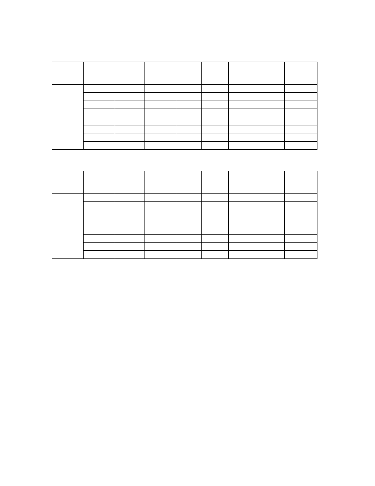
Table 1-1.DATA-20 Data Channel Configurations
Data Rate MUX Hardware Channels Interface(s)
1.5 Mbps-8 Mbps 2 or 4 x E1/T1 2 or 4 G.703, E1/T1
512 kbps-2 Mbps QAM Modem 1 Fractional E1/T1
512 kbps-2 Mbps QAM Modem 1 V35, RS449
1.3.2 Standalone Operation
The DATA-20 may be used as a standalone digital radio with an interface in the modem or with a
Multiplexer with 2 or 4 E1/T1 interfaces. The Multiplexer has an overhead channel which can be
utilized by the customer
DataNex EMS Wireless, DATA-20 Digital Radio

1-3 System Description
A
A
1.3.3 Hot Standby (Protected) Operation
The product in a hot standby configuration as depicted in Fig.1-2, using two DATA-20 radios and
a TP64 transfer panel.
Data-20 RADIO A
RX
RX RF
SPLITTER
RX
Data-20 RADIO B
TP64 TRANSFER
PANEL
DATA
DATA
TRANSFER
DATA
CNTL
DATA
SWITCH/
LOGIC
CNTL
Figure 1-2. DATA-20 Hot Standby – Two Discrete Radios with Transfer Panel
1.4 Regulatory Notices
TX
TX RF
RELAY
TX
NTENN
DUPLEXER
FCC Part 15 Notice
This equipment has been tested and found to comply with the limits for a Class A digital device,
pursuant to part 15 of the FCC Rules. These limits are designed to provide reasonable protection
against harmful interference when the equipment is operated in a commercial environment. This
equipment generates, uses, and can radiate radio frequency energy and, if not installed and used
in accordance with the instruction manual, may cause harmful interference to radio
communications. Operation of this equipment in a residential area is likely to cause harmful
interference, in which case the user will be required to correct the interference at his expense.
Any external data or audio connection to this equipment must use shielded cables.
DataNex EMS Wireless, DATA-20 Digital Radio

System Description 1-4
1.5 System Description (QAM)
1.5.1 Introduction
The product is a full-duplex digital radio. The following sections describe the TX system, RX
system, followed by sub-system components. Please reference the accompanying block
diagrams for clarification.
We will follow the typical end-to-end progression of a radio system starting with the TX baseband
inputs, to the QAM modulator, followed by the upconversion process and the power amplifier.
We then proceed to the RX preamplifier input, the downconversion process, followed by the QAM
demodulator and baseband outputs.
Antenna
Duplexer
Uni ver sal
Input AC
(DC Optional)
Serial PC Interface
Status/Command/Control I/O
Transfer Panel I/O
RX
TX
+15 VDC
PA Control/
Current
Sense
Power
Supply
RF Linear
PA
+5/+15 VDC
130 Watt
System
Monitor
(A/D)
400 MHz-
1.5 GHz
Back
RF Module
Down Converter
Up Converter
NMS
System CPU
Remot e I/O
Front Panel Inter face
Data, Address, I
Front
Panel
4 x 20 LCD Display
Status LEDs
BarGraph
70 MHz
2
C, SPI Bus
Front Panel
Ribbon Cable
QAM Modem Module
IF Card
Down Converter
Up Converter
12.8 MHz
QAM Modem
Intelligent
MUX
4 Port
Demodulator
Modul ato r
Data/Voice
Interface
Channel 1
Channel 2
Channel 3
Channel 4
Trun k
Figure 1-3. DATA-20 System Block Diagram
.
All modules (excluding the Front Panel and Power Amplifier) are interconnected via the
backplane that traverses the entire width of the unit. The backplane contains the various
communication buses as well as the PA (Power Amplifier) control and redundant transfer
circuitry. The power supply levels and status are monitored on the backplane and the NMS/CPU
card processes the data.
DataNex EMS Wireless, DATA-20 Digital Radio

1-5 System Description
Figure 1-4. Location of theDATA-20Backplane and Power Amplifier
The NMS/CPU card incorporates microprocessor and FPGA logic to configure and monitor the
overall operation of the system via front panel controls, LCD screen menus, status LEDs and the
bar graph display. Module settings are loaded into the installed cards and power-up default
settings are stored in non-volatile memory. LCD screen menu software is uploaded into memory,
providing field upgrade capability. A Windows-based PC interface is available for connection at
the rear panel DATA port.
1.5.2 QAM Modulator/IF Upconverter
TRUNK
I/O
TXD
RXD
IF REF
CLK OUT
IF OUT
LED
STATUS
LEVEL
TRANSLATOR
RS232
TRANSLATOR
IF IN
AGC
INTERLEAVE
RAM
QAM
ENCODER
QAM
DECODER
INTERLEAVE
RAM
NCO
IF
SYNTH
FPGA
FPGA
EEPROM
uC
EEPROM
RATE CONVERTER
PLL FIFO
DIGITAL
POT
STATUS
SPI
DEBUG
OCXO
12.8 MHz
IF
MICRO
CONTROLLER
LEGEND
NO
CONNECTION
uC BUS
REF CLK
DATA & CLK
BUS
I2C IN
BUS
DATA & CLK
OUT
BUS
IN
BUS
REF CLK
OUT
The QAM (Quadrature Amplitude Modulation) Modulator is the transmit portion of the QAM
Modem card. The QAM Modem also houses the IF Up/Down Converter. The QAM Modulator
utilizes the upconverter portion of the IF daughter card.
The QAM Modulator accepts the aggregate data stream via the backplane (see Figure 1-5
above). The module performs modulation at a carrier frequency of 6.4 MHz, adding FEC
(Forward Error Correction) bits while interleaving the blocks of data. The result is a very
spectrally efficient, yet robust linear modulation scheme. This process requires an ultra-stable
DataNex EMS Wireless, DATA-20 Digital Radio
Figure 1-5. QAM Modem Block Diagram

System Description 1-6
master clock provided by an OCXO (oven controlled crystal oscillator) that is accurate to within
0.1 ppm.
IF Input
6.4 MHz
-20 dBm
BPF
6.4 MHz
Synth Level
76.4 MHz PLL
BPF
70 MHz
Loop
Filter
Synth
Lock
VCO
Exciter
Level
IF Output
70 MHz
-10 dBm
Clk
Ref
Data
Enbl
PLL
Figure 1-6. IF Upconverter Block Diagram
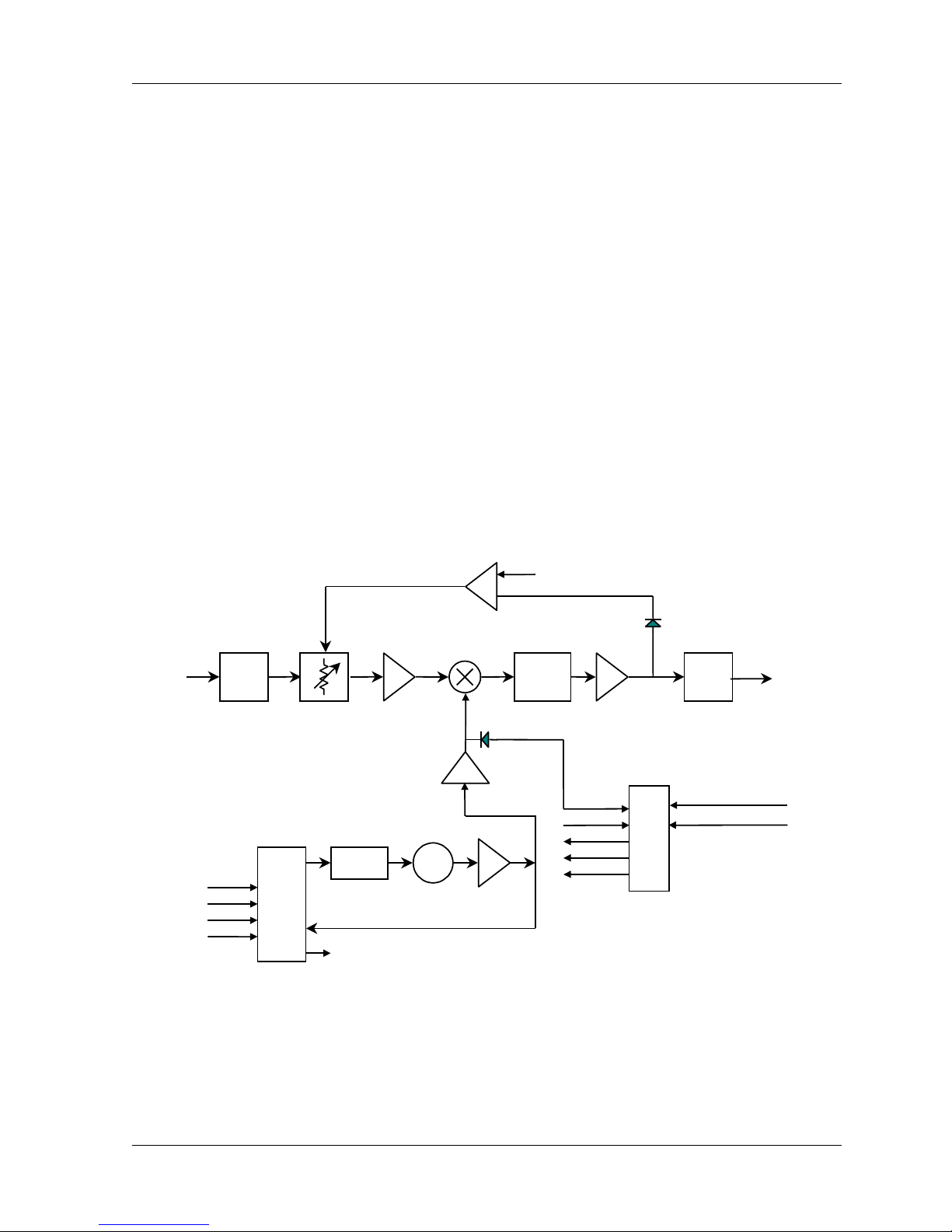
The resultant carrier is translated up to 70 MHz by the IF Upconverter (see Figure 1-6). This is
accomplished by a standard mixing of the carrier with a phase-locked LO. A 70 MHz SAW filter
provides an exceptional, spectrally-clean output signal.
1.5.3 RF Upconverter
70 MHz IF
Input
BPF
70 MHz
Diplexer
Synth Level
BPF
RF Output
BPF
Loop
Data
Clk
Enbl
Ref
PLL
Filter
Synth Lock
DataNex EMS Wireless, DATA-20 Digital Radio
TX ALC
VCO
Synth Level
PLL
Synth Lock
Synth Data
Synth Clk
Synth Enbl
uP
IPA Level
RFA Fwd Pwr Level
RFA Rev Pwr Level
Temp Sense
NMS
12.8 MHz Ref Osc
1-7 System Description
Figure 1-7. RF Upconverter Block Diagram
The IF output carrier of the IF Upconverter daughter card is fed to the transmit portion of the RF
Module via an external (rear panel) semi-rigid SMA cable. This module performs the necessary
upconversion to the RF carrier (see Figure 1-7). There is an on-board CPU for independent
control of the critical RF parameters of the system.
Since this is a linear RF processing chain, an automatic leveling control loop (ALC) is
implemented here to maintain maximum available power output (and therefore maximum system
gain). The ALC monitors the PA forward power (FWD) output sample, and controls the
upconverter gain per an algorithm programmed in the CPU. The ALC also controls the power-up
RF conditions of the transmitter output.
1.5.4 Power Amplifier (PA)
The Power Amplifier (PA) is a separate module that is mounted to a heat sink and is fan-cooled
for reliable operation. The PA is a design for maximum linearity in an amplitude modulationbased system.
1.5.5 RF Downconverter
RF Input
BPF Diplexer
Atten
Data
Clk
Enbl
Ref
PLL
RF AGC
Loop
Filter
Synth
Lock
Preamp
ALC
Loop Amp
VCO
PLL
70 MHz
ALC Control
Synth Level
Synth Lock
Synth Data
Synth Clk
Synth Enbl
IF Amp
ALC
Det
IF Output
BPF
70 MHz
uP
70 MHz
to QAM
Demod
NMS
12.8 MHz Ref Osc
Figure 1-8. RF Downconverter Block Diagram
The receiver handles the traditional RF to IF conversion from the carrier to 70 MHz (see Figure 1-
8). Considerations are given to image rejection, intermodulation performance, dynamic range,
agility, and survivability. A separate AGC loop was assigned to the RF front end to prevent
intermodulation and saturation problems associated with reception of high level undesirable
DataNex EMS Wireless, DATA-20 Digital Radio

System Description 1-8
interfering RF signals resulting from RF bandwidth that is much wider than the IF bandwidth. The
linear QAM scheme is fairly intolerant of amplifier overload.
1.5.6 QAM Demodulator/IF Downconverter
IF Input
70 MHz
BPF
70 MHz
BPF
6.4 MHz
IF Output
6.4 MHz
-10dBm
Clk
Data
Enbl
Ref
PLL
Loop
Filter
Synth
Lock
76.4 MHz PLL
Synth Level
AGC Control
VCO
Figure 1-9. IF Downconverter Block Diagram
The QAM (Quadrature Amplitude Modulation) Demodulator is the receive portion of the QAM
Modem card. The QAM Modem also houses the IF Up/Down Converter. The QAM Demod
utilizes the downconverter portion of the IF daughter card.
The IF Downconverter receives the 70 MHz carrier from the receiver portion of the RF Module via
an external semi-rigid cable and directly converts the carrier to 6.4 MHz by mixing with a lownoise phase-locked LO (see Figure 1-9). System selectivity is achieved through the use of a 70
MHz SAW filter.
The QAM Demod receives and demodulates the 6.4 MHz carrier (see Figure 1-7). The
demodulation process includes the FEC implementation and de-interleaving that matches the
QAM modulator in the transmitter, and the critical “data assisted recovery” of the clock. This
process requires an ultra-stable master clock provided by an OCXO (oven controlled crystal
oscillator).
The output is an aggregate data stream that is distributed to the trunk port for if the data
input/output is out of the Modem, or to the backplane for connection to the multiplexer connected
on the backplane.
DataNex EMS Wireless, DATA-20 Digital Radio

2 Installation
2.1 Unpacking
The following is a list of all included items.
Description Quantity
Digital Radio (3RU chassis) 1
Rack Ears (with hardware) 4
Extender Card (Universal QAM) — optional 1
Power Cord (IEC 3 conductor for AC, 2-wire for DC) 2
Manual ( or Soft copy on a CD) 1
Test Data Sheet (customer documentation) 1
Be sure to retain the original boxes and packing material in case of return shipping. Inspect all
items for damage and/or loose parts. Contact the shipping company immediately if anything
appears damaged. If any of the listed parts are missing, call the distributor or the factory
immediately to resolve the problem.
2.2 Notices
CAUTION
DO NOT OPERATE UNITS WITHOUT AN ANTENNA, ATTENUATOR, OR LOAD CONNECTED
TO THE ANTENNA PORT. DAMAGE MAY OCCUR TO THE TRANSMITTER DUE TO
EXCESSIVE REFLECTED RF ENERGY.
ALWAYS ATTENUATE THE SIGNAL INTO THE RECEIVER ANTENNA PORT TO LESS THAN
3000 MICROVOLTS. THIS WILL PREVENT OVERLOAD AND POSSIBLE DAMAGE TO THE
RECEIVER MODULE
WARNING

Installation 2-2
HIGH VOLTAGE IS PRESENT INSIDE THE POWER SUPPLY MODULE WHEN THE UNIT IS
PLUGGED IN. REMOVAL OF THE POWER SUPPLY CAGE WILL EXPOSE THIS POTENTIAL
TO SERVICE PERSONNEL. TO PREVENT ELECTRICAL SHOCK, UNPLUG THE POWER
CABLE BEFORE SERVICING. UNIT SHOULD BE SERVICED BY QUALIFIED PERSONNEL
ONLY.
PRE-INSTALLATION NOTES
Always pre-test the system on the bench in its intended configuration prior to installation at a
remote site. Avoid cable interconnection length in excess of 1 meter in strong RF environments.
We highly recommend installation of lightning protectors to prevent line surges from damaging
expensive components.
2.3 Rack Mount
The product is normally rack-mounted in a standard 19” cabinet. Leave space clear above (or
below) the unit for proper air ventilation of the card cage. The rack ears are typically mounted as
shown in Figure 2-1. Other mounting methods are possible by changing the orientation of the
rack ears.
Figure 2-1.DATA-20 Typical Rack Mount Bracket Installation
2.4 Duplexer: Internal/External
Various duplexers, both internal and external, can be utilized. For current duplexers utilized with
the radios, please see the Appendix.
DataNex EMS Wireless, DATA-20 Digital Radio

2-3 Installation
2.5 Rear Panel Connections & Indicators
Please refer to the Figure 2-2 for a pictorial of a typical product rear panel (internal duplexer).
Following is a descriptive text of the connections and LED indicators.
Figure 2-2.DATA-20 Rear Panel Connections
Power Supply:
Inputs: AC: Universal Input, 100-240V, 50/60 Hz; IEC 3
DC: 24v/48v (Isolated Input); 2 pin socket (custom)
Status LED: +12V: Green LED indicates +12 volt supply OK
+5V: Green LED indicates +5 volt supply OK
NMS Card
I/O Port: RS232 PC access; 9 pin D-sub (female)
Reset Switch: Activates hard system reset
Status LED: Green LED Indicates CPU OK
conductor
DataNex EMS Wireless, DATA-20 Digital Radio

Installation 2-4
QAM Modem
I/O Ports: TRUNK: Data I/O 15pin D-sub (female) HD
RF
Connectors:
70 MHz
OUT:
70 MHz
IN:
Status LED: MOD: GREEN indicates Modulator Lock
DEMOD: GREEN indicates Demod Lock
Up/Down Converter Module
RF
TO PA: SMA (female), Upconverter output to be applied
Connectors:
70 MHz
IN:
RF IN: SMA (female), Receiver input.
70 MHz
OUT:
SMA (female); Modulator output
SMA (female); Demod input
to linear Power Amplifier module (internal to
radio).
SMA (female), Modulated IF input from QAM
Modulator.
SMA (female); Downconverter output to
Modulator input
Status LED: TX
GREEN indicates TX AFC LOCK
LOCK:
Flashing RED indicates LOSS OF TX LOCK
RX
LOCK:
GREEN indicates RX AFC LOCK and strong RX
signal
YELLOW indicates RX AFC LOCK and nominal
RX signal
RED (continuous) indicates RX AFC LOCK and
weak RX signal
RED (flashing) indicates LOSS OF RX LOCK
DataNex EMS Wireless, DATA-20 Digital Radio

2-5 Installation
RF I/O Panel
RF
Connectors:
PA IN: SMA (female), RF cabling to internal PA
RX OUT: SMA (female), RF cabling from internal
SEMI-RIGID CABLE
Ensure that the cables are secure and tightly attached.
Check for any damage (kinks or breaks in the copper sheath).
ANTENNA: Type N (female), RF cabling from internal PA
module.
module.
duplexer.
2.6 Power Requirements
2.6.1 Power Supply Card Slot Details
The leftmost slot in the DATA-20 card cage (as viewed from the rear of the unit) is designated as
the “PRIMARY A” power supply. The main bus voltages (+5 and +/-12) are summed in the
backplane and provide the supply the plug-in modules.
NOTE: The front panel LCD screen displays the system supply voltages and the
nomenclature follows the physical location of the power supply modules.
2.6.2 AC Line Voltage
The DATA-20 uses a high reliability, universal input switching power supply capable of operating
within an input range of:
100 - 240 VAC; 50/60 Hz
The power supply module is removable from the unit and a perforated cage protects service
personnel from high voltage. The power supply is fan cooled due to high power consumption by
the PA.
CAUTION
High voltage is present when the unit is plugged in. To prevent electrical shock, unplug the power
cable before servicing. Power supply module should be serviced by qualified personnel only.
DataNex EMS Wireless, DATA-20 Digital Radio

Installation 2-6
2.6.3 DC Input Option
An optional DC input power supply is available for the DATA-20; using high reliability, DC-DC
converter(s) capable of operation within the following input ranges (dependent upon nominal input
rating):
Nominal DC Input Operating Input Range
24 Volt: 20 – 28 VDC
48 Volt: 32 – 64 VDC
The DC input is isolated from chassis ground and can be operated in a positive or negative
ground configuration. The power supply module is removable from the unit and no high voltages
are accessible.
2.6.4 Fusing
For AC modules, the main input fuse is located on the switching power supply mounted to the
carrier PC board and the protective cage may be removed for access to the fuse.
For DC modules, all fusing is located on the carrier PC board.
Always replace any fuse with same type and rating. Other fuses are present on the board, and
are designed for output fail-safe protection of the system. All output fuse values are printed on
the backside of the PC board to aid in replacement.
NOTE: If a fuse does blow in operation, investigate the possible cause of the failure prior to
replacing the fuse, as there is adequate built-in protection margin.
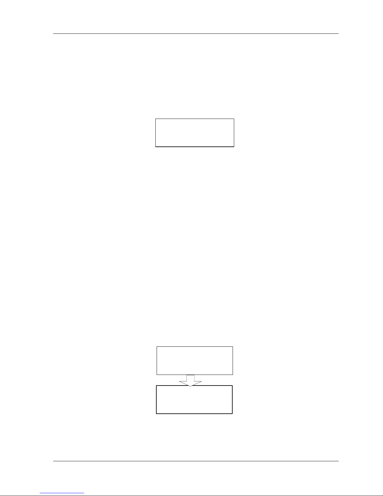
2.7 Power-Up Setting
As shipped, the DATA-20 will radiate into the antenna upon power-up, THIS ASSUMES THAT
THE ANTENNA LOAD IS GOOD (LOW VSWR). If the VSWR of the load causes a high reverse
power indication at the PA, the red VSWR LED will light and the transmitter will cease radiating.
This is called the “AUTO” setting in the QAM RADIO CONTROL screen (see below).
The LCD screen (“QAM RADIO TX CONTROL”) selects the power-up state and controls the
radiate function of the TX unit.
Go to the MAIN MENU:
DataNex EMS Wireless, DATA-20 Digital Radio

2-7 Installation
Data-20 Main Menu
METER
QAM RADIO
SYSTEM
ALARMS/FAULTS
Scroll
Scroll to QAM Radio, press ENTER.
Select Launch Screen for CONTROL TX, press ENTER:
QAM Radio Launch
CONTROL
TXA
QAM Radio TX Control
Verify the AUTO setting.
AUTO: Transmitter will protect its PA by “folding back” the ALC under bad
ON: Transmitter will remain in radiate at full power under all antenna
OFF: Transmitter in standby mode.
TX Radiate
AUTO
load VSWR condition (default setting)
port conditions (not recommended).
DataNex EMS Wireless, DATA-20 Digital Radio

Installation 2-8
2.8 Data Interface
2.8.1 4xE1/T1 MUX Channel Configurations
Trunk I/O Async Data Channel
Channel 3/4 (E1/T1)Channel 1/2 (E1/T1)
Aux Channel 1 Aux Channel 2
EMS
Figure 2-3. 4XE1/T1 MUX Panel
The 4xE1/T1 MUX is a high speed card (up to 8 MBPS) that has a total of 7 ports. Table 2-1
summarizes the capabilities.
DataNex EMS Wireless, DATA-20 Digital Radio

2-9 Installation
Table 2-1.DATA-20 4xE1/T1 MUX Data Channel Configurations
Chnl Data
Rate
4xE1
(BPS)
1 2.048 K 1.544 K 2.048 K 1.544 K 2.048 K 1.544 K G.703,
2 2.048 K 1.544 K 2.048 K 1.544 K --- --- G.703,
3 2.048 K 1.544 K --- --- --- --- G.703,
4 2.048 K 1.544 K --- --- --- --- G.703,
* Aux1 128 K 96 K 64 K 48 K 32 K 24 K V.35,
* Aux2 128 K 96 K 64 K 48 K 32 K 24 K V.35,
ASYNC
Data
9600 7200 4800 3600 2400 1800 RS232
Data
Rate
4xT1
(BPS)
Data
Rate
2xE1
(BPS)
Data
Rate
2xT1
(BPS)
Data
Rate
1xE1
(BPS)
Data
Rate
1xT1
(BPS)
Interface
DSX-1
DSX-1
DSX-1
DSX-1
RS449
RS449
* AUX Channels 1-2 can be combined to form 2xCh.1 or 2xCh.2 (i.e., in 4xE1 mode, AUX could
be a single channel of 256 KBPS)
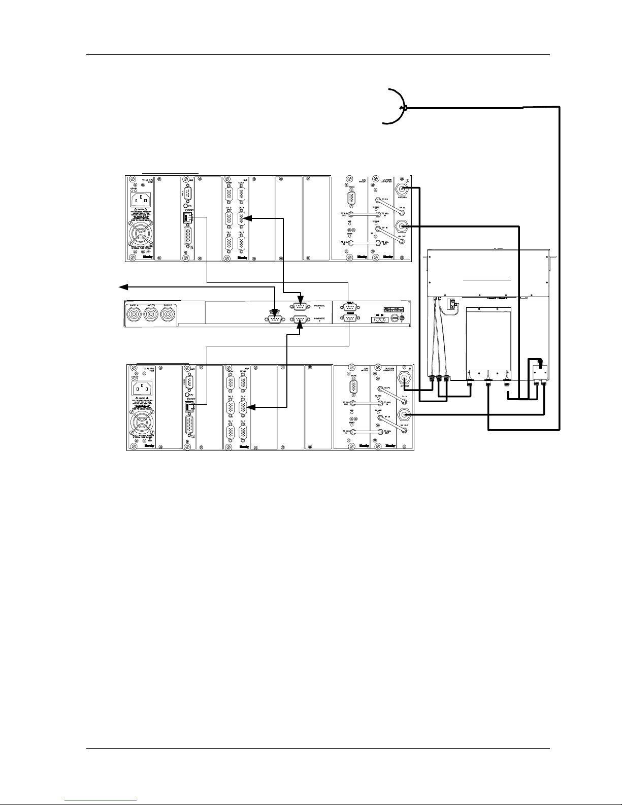
2.9 Hot Standby (Protected) Configuration
The DATA-20 may be installed in a hot standby (protected) configuration. This consists of
twoDATA-20 chassis with a TP64 transfer panel (Figure 2-5)
Transfer Panel Connection
The usual hot standby configuration uses an external duplexer. This minimizes RF losses and
provides independent TX and RX module switching. A duplexer should already be mounted on
the TP64 chassis. Alternatively, rack mounted duplexers (typical for tighter channel spacings)
may be provided. The connections are the same, although the physical location is different.
A power divider (used to split the signal equally to two receivers) is required in this mode. The
input to the power divider connects directly to the duplexer with an N-N (male) adapter.
See Figure 2-4 for installation details.
DataNex EMS Wireless, DATA-20 Digital Radio
Installation 2-10
A
NTENNA
DATA-20 Radio A
DATA
DATA
TP64 Rear Panel
Data-20 Radio B
RJ45
RJ45
DATA
Figure 2-4.DATA-20 Hot Standby – with Transfer Panel
TP64 Top View
2.9.1 Hot/Cold Standby Modes
Hot Standby ( *preferred)
Hot standby leaves both transmitters in the RADIATE ON condition, and the transfer logic
controls the RF relay to select the active transmitter, thereby decreasing switchover time. This is
the preferred operating mode.
Cold Standby
Cold standby can be used in situations where lower power consumption is a priority. In this
mode, the transfer logic will control the RADIATE function of each transmitter, turning the RF
DataNex EMS Wireless, DATA-20 Digital Radio
2-11 Installation
output ON (in tandem with the RF relay) as required for switching. This will increase switching
time and a corresponding increase in data loss during the switchover.
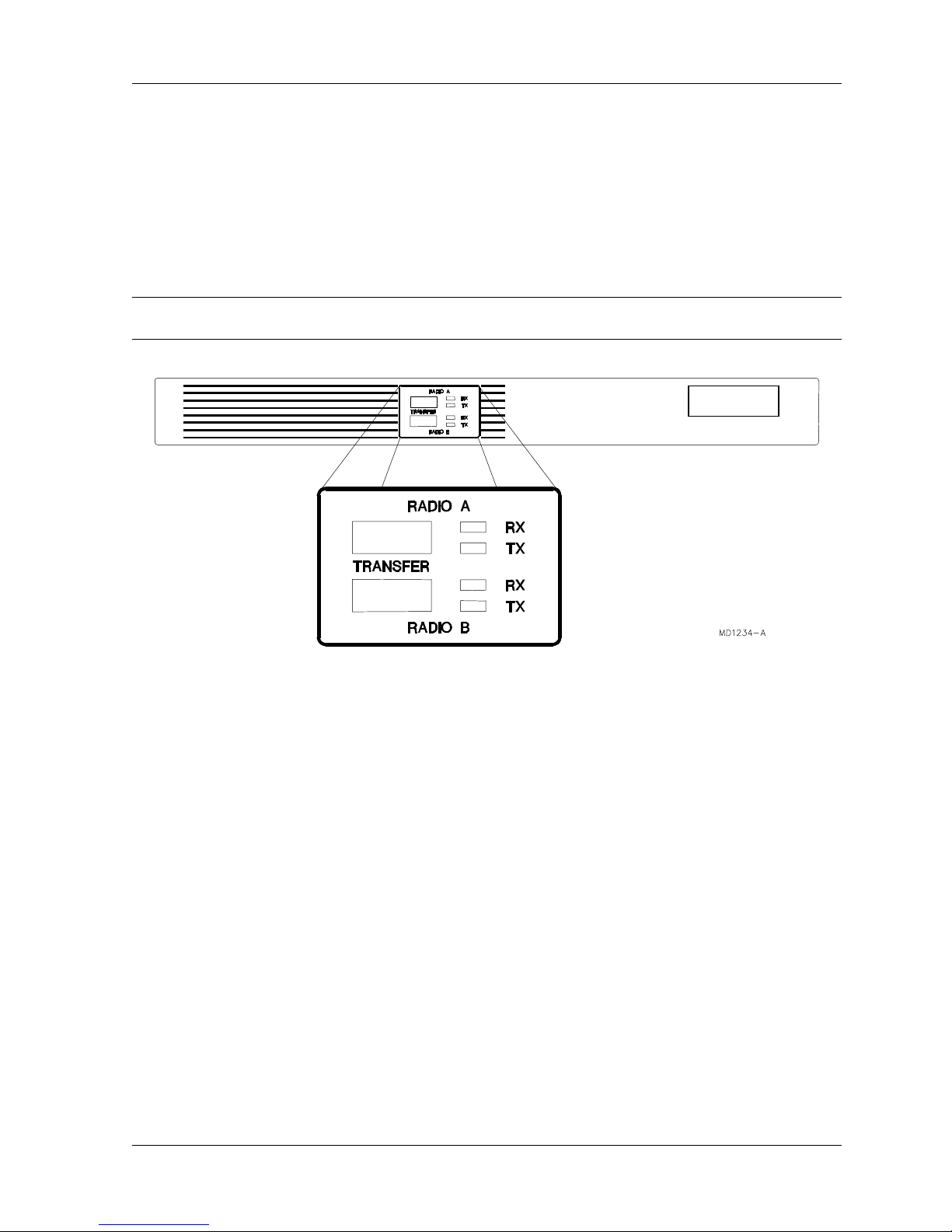
2.9.2 Hot Standby Control using the TP64
2.9.2.1 TP64 Front Panel Controls and Indicators
Note: See the following section for a detailed description of the Master/Slave logic implemented
in the TP64.
DataNex
Figure 2-5. TP64 Front Panel
LED Indicators
Green: The indicated module is active, and that the module is performing within
its specified limits.
Yellow: The indicated module is in standby mode, ready and able for back-up
transfer.
Red: There is a fault with the corresponding module. It is not ready for
backup, and the TP64 will not transfer to that module.
TRANSFER Switches
The RADIO A and RADIO B transfer switches cause the selected radio to become active, and the
Master. See Section 3.4 (following) for further details.
2.9.2.2 Master/Slave Operation & LED Status
The TP64 operates in a Master/Slave logic mode. In the power up condition, the Master is
RADIO A. This means that RADIO A is the default active unit. The following logic applies to hot
or cold standby, external or internal duplexer configurations.
DataNex EMS Wireless, DATA-20 Digital Radio
Installation 2-12
Table 2-3. TP64 Transmitter Master/Slave Logic
Selected
Master
A OK OK GRN YEL A A
A OK FAIL GRN RED A A
A FAIL OK RED GRN B B
Logic
A-Master
B-Master
A FAIL FAIL RED RED N/A A
B OK OK YEL GRN B B
B OK FAIL GRN RED A A
B FAIL OK RED GRN B B
Logic
B FAIL FAIL RED RED N/A B
Selected
Master
A OK OK GRN YEL A A
A OK FAIL GRN RED A A
A FAIL OK RED GRN B B
Logic
A-Master
B-Master
A FAIL FAIL RED RED N/A None
B OK OK YEL GRN B B
B OK FAIL GRN RED A A
B FAIL OK RED GRN B B
Logic
B FAIL FAIL RED RED N/A None
TXA
Status
TXB
Status
TXA
LED
TXB
LED
Active TX TX Relay
Table 2-4. TP64 Receiver Master/Slave Logic
RXA
Status
RXB
Status
RXA
LED
RXB
LED
Active RX RX Data &
Position
Clk
A-Master Logic (default power-up):
If RADIO A is “good”, the TP64 will remain in RADIO A position, regardless of RADIO B’s status.
If RADIO A fails, the TP64 will switch to RADIO B (assuming that RADIO B is “good”)
If RADIO A then returns to a “good” condition, the TP64 will switch back to RADIO A (the default
Master)
Manual Switchover to B-Master Logic
The front panel switch on the TP64 can be used to manually force the system to a new Master.
By pressing the RADIO B button, RADIO B now becomes the Master, and the TP64 will
switchover to RADIO B (assuming that RADIO B is “good”).
The default A-Master Logic will then switch to B-Master Logic, as outlined in Tables 2-3 and 2-4.
DataNex EMS Wireless, DATA-20 Digital Radio

2-13 Installation
Note: Manual switching of the Master is often used to force the system over to the standby unit.
The user may want to put more “time” on the standby unit after an extended period of
service. In Hot Standby configurations, this will not buy the user anything in terms of
reliability. In Cold Standby, the “burn time“ is more significant, since the RF power
amplifier device operating life becomes a factor.
2.9.2.3 DATA-20 Software Settings
The full array of available settings for the Control and Configuration menus are located in Section
3—Operation of the Front Panel. Shown here are the applicable settings for redundant standby
systems.
Clock Settings
For proper operation, the clock settings (located in the QAM Radio/Config/Modem Menu) must be
set as follows:
QAM Interface
Intfc
Tx In Clock
Clk Phase
Rx Clock Out
Clk Phase
Trunk Out
Clk Source
Clk Phase
TRUNK
INVERTED
NORMAL
EXTERNAL
NORMAL
Control Settings
These settings configure the transmitter for hot (or cold) standby.
It is important that each DATA-20 radio in the redundant pair is configured identically for proper
operation.
In the SYSTEM TRANSFER menu:
DataNex EMS Wireless, DATA-20 Digital Radio
Transfer
Tx Transfer
Rx Transfer
______
______
Installation 2-14
Tx Transfer:
OFF: Turns Transmitter Transfer Mode OFF.
Rx Transfer:
OFF: Indicates the receivers are not switched.
In the QAM Radio TX Control menu:
QAM Radio Tx Control
TX Radiate
______
Tx Radiate:
ON: Configures the Transmitter to always RADIATE.
2.9.2.4 TP64 Settings
The TP64 software settings are contained in the internal firmware. Aside from the front panel
RADIO A/B Master Select (as described above), there are no user-configurable settings in the
TP64 unit.
2.9.3 Hot Standby Control with Single Unit
2.9.3.1 DATA-20 Software Settings
The full array of available settings for the Control and Configuration menus are located in Section
3—Operations. Shown here are the applicable settings for single systems.
Clock Settings
All controls and indications can be found on the DATA-20 front panel LCD display (located in the
QAM Radio/Config/ModA or ModB Menu).
Control Settings
These settings configure the transmitter for hot (or cold) standby.
DataNex EMS Wireless, DATA-20 Digital Radio
QAM Interface
Intfc
Clk Phase
RADIO(BKPLN)
Tx In Clock
NORMAL

2-15 Installation
It is important that each DATA-20 radio in the redundant pair is configured identically for proper
operation.
In the SYSTEM TRANSFER menu:
Transfer
Tx Transfer:
HOT: Configures the Transmitter for HOT STANDBY
operation.*(preferred)
COLD: Configures the Transmitter for COLD STANDBY operation.
Rx Transfer:
ON: Places the receivers in both active and transfer mode.
In the QAM Radio TX Control menu:
Tx Radiate:
AUTO: Software controls the RADIATE function.
Tx Transfer
Rx Transfer
QAM Radio Tx Control
TX Radiate
______
______
______
2.10 Site Installation
The installation of the DATA-20 involves several considerations. A proper installation is usually
preceded by a pre-installation site survey of the facilities. The purpose of this survey is to
familiarize the customer with the basic requirements needed for the installation to go smoothly.
The following are some considerations to be addressed (refer to Figure 2-8 for Site Installation
Details).
Before taking the product to the installation site verify that the interface connections are
compatible with the equipment to be connected. Also, locate the information provided by the path
analysis that should have been performed before ordering the equipment. At the installation site,
particular care should be taken in locating the product in an area where it is protected from the
weather and as close to the antenna as possible. Locate the power source and verify that it is
suitable for proper installation.
The installations should only be performed by qualified technical personnel
only.
DataNex EMS Wireless, DATA-20 Digital Radio

Installation 2-16
2.11 Antenna/Feed System
2.11.1 Antenna Installation
For compliance with FCC RF Exposure requirements the following has to be adhered to:-
1. All antenna installation and servicing is to be performed by qualified technical personnel
only. When servicing the antenna, or working at distances closer than those noted below,
ensure the transmitter has be disabled.
2. Typically, the antenna connected to the transmitter is a directional (high gain) antenna,
fixed-mounted on the side or top of a building, or on a tower. Depending upon the
application and the gain of the antenna, the total composite power could exceed 20 to
61watts EIRP. The antenna location should be such that only qualified technical
personnel can access it, and that under normal operating conditions the antenna
separation from the user is required to be located at the distance of 3.5meters or more.
EIRP at the antenna is calculated as follows:-
Transmit power – Cable loss + Antenna Gain = EIRP
Eg.
+31.1dBm – 6dB(for 100m LDF5-50A) +36dBi = 61.1Bmi
DataNex EMS Wireless, DATA-20 Digital Radio
3 Front Panel Operation
3.1 Introduction
This section describes the front panel operation of the DATA-20 digital radio/modem. This
includes:
• LCD display (including all screen menus)
• Cursor and screen control buttons
• LED status indicators
3.2 Front Panel Operation
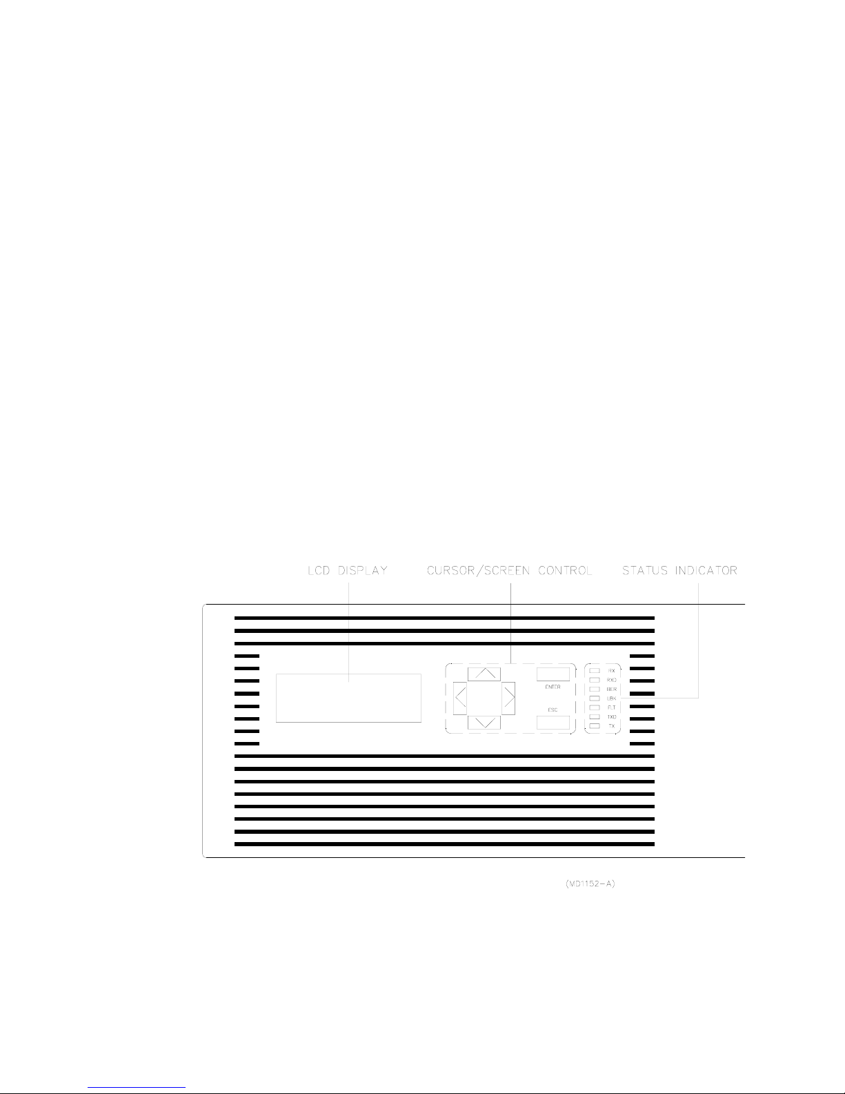
A picture of the DATA-20 front panel is depicted in Figure 3-1 below.

Front Panel Operation 3-2
Figure 3-1.DATA-20 Front Panel
3.2.1 LCD Display
The Liquid Crystal Display (LCD) on the DATA-20 front panel is the primary user interface and
provides status, control, configuration, and calibration functionality. The menu navigation and
various screens are explained in detail later in this section.
Backlight:
An automatic backlight is built-in to the LCD for better clarity under low-light conditions. This
backlight is enabled on power-up and will automatically turn off if there is no button activity by the
user. The backlight will automatically turn on as soon as any button is pressed.
Contrast Adjustment:
Internal adjustment on board (in back of front panel button PCB).
3.2.2 Cursor and Screen Control Buttons
The buttons on theDATA-20 front panel are used for LCD screen interface and control functions:
ENT
ESC
<ENTER> Used to accept an entry (such as a value,
a condition, or a menu choice).
<ESC> Used to “back up” a level in the menu
structure without saving any current
changes.
<UP>,<DOWN> Used in most cases to move between the
menu items. If there is another menu in
the sequence when the bottom of a menu
is reached, the display will automatically
scroll to that menu.
DataNex EMS Wireless, DATA-20 Digital Radio
<LEFT>,<RIGHT> Used to select between conditions (such
as ON/OFF, ENABLED/DISABLED,
LOW/HIGH, etc.) as well as to increase or
decrease numerical values.

3-3 Front Panel Operation
3.2.3 LED Status Indicators
Table 3-1. LED Status Indicator Functions
LED Name Function
RX Receiver Green indicates that the receiver is enabled, the
synthesizer is phase-locked, and a signal is
being received.
RXD Receive Data Green indicates that valid data is being received.
BER Bit Error Rate Flashes red for each data error detected.
FLT Fault General fault light (red). Consult the STATUS
menus for out of tolerance conditions.
LBK Loopback Red indicates analog or digital loopback is
enabled.
TXD Transmit Data Green indicates the modem clock is phase-
locked and data is being sent.
TX Transmitter Green indicates the transmitter is radiating, and
the RF output (forward power) is above the
factory-set threshold.
3.2.4 Screen Menu Tree Structure
Figures 3-2a, b and c, located on pages 3-7, 3-8, 3-9 and 3-10, show the tree structure of the
screen menu system. The figures group the screens into functional sets. There may be minor
differences in the purchased unit, due to software enhancements and revisions. The current
software revision may be noted in the SYSTEM sub-menu (under INFO).
In general, <ENTER> will take you to the next screen from a menu choice, <UP> or <DOWN> will
scroll through screens within a menu choice, and <ESC> will take you back up one menu level.
Certain configuration screens have exceptions to this rule, and are noted later in this section.
CAUTION
DO NOT change any settings in the CONFIGURE or CALIBRATE screens. The
security lock-out features of the software may not be fully implemented, and
changing a setting will most likely render the system non-operational!
DataNex EMS Wireless, DATA-20 Digital Radio

Front Panel Operation 3-4
3.3 Main Menu
The main menu appears on system boot-up, and is the starting point for all screen navigation.
Unlike most other screens in the software, the main menu scrolls up or down, one line item at a
time.
Data-20 MAIN MENU
METER
QAM RADIO
SYSTEM
ALARMS/FAULTS
Scroll
DataNex EMS Wireless, DATA-20 Digital Radio

3-5 Front Panel Operation
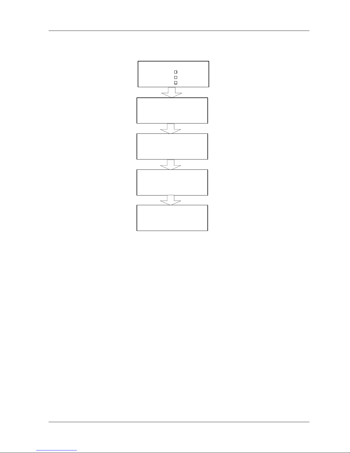
3.3.1 Launch Screens
The LAUNCH screen allows the user to quickly get to a particular screen within a functional
grouping in the unit. The logic is slightly different than other screens. Figure 3-2 below contains
a “Launch Screen Navigation Guide” to assist the user in locating the desired Radio screen.
Data-20 MAIN MENU
METER
QAM RADIO
ENT
Cycle through STATUS, CONTROL,
CONFIGURE choices:
QAM Radio Launch
STATUS
MODEM
Move cursor to
next line
SYSTEM
ALARMS/FAULTS
QAM Radio Launch
CONTROL
MODEM
Scroll
QAM Radio Launch
CONFIGURE
MODEM
Cycle through MODEM,
TX, RX choices:
QAM Radio Launch
STATUS
MODEM
Figure 3-2. Launch Screen Navigation Guide
QAM Radio Launch
STATUS
TX
TX STATUS chosen,
ENT
press ENTER to view.
QAM Radio TX Status
FreqA
MHz
Page down/up with
down or up arrow.
More Screens
(see Menu Flow
Diagram)
Press ESCAPE to return to
ESC
previous levels.
QAM Radio Launch
STATUS
RX
DataNex EMS Wireless, DATA-20 Digital Radio

Front Panel Operation 3-6
This page is intentionally blank.
DataNex EMS Wireless, DATA-20 Digital Radio

3-7 Front Panel Operation
DataNex EMS Wireless,
DATA-20 Digital Radio
Power Supply
Primar
y
+5VD
+15VD
AC
5.00
V
15.00
V
AUDIO DEC
CARD ID
Chnl Cd
MU
X
MUX0
CHC1
Basic Card Setup
QAM Mode
m
RF Tx
QMA
TXA
CARD ID
Factory Cali brate
RADIO RX
QAM Mode
m
RADIO TXSyste
m
CARD ID
AUDIO ENC
RF R
X
RXA
ENC1
DEC1
AUDIO DEC
(see Factor
y
Calibration
submenu)
System Information
SECURITY
FIRMWARE
USE
R
Vx.xx
METE R
Meter
Bargraph DECDR 1
Backlight AUTO
Led DSP
A
System Date
Month
Year
Da
y
29
00
06
System Time
Minutes
Seconds
Hour 15
48
35
A
LARMS/FAUL
T
Alarm(s)
Total Alarms Since
Reset-1
ALARMS - A
FAULTS - A
ALARMS - B
FAULTS - B
Fault(s)
Alarm(s)
Rev Pwr > 0.25
W
15:20:24 6/29/00
Total Faults Since
Reset-1
Figure 3-2a
LCD SCREEN MENU
Figure 3-2a
LCD SCREEN MENU
M
ETER
QAM RADIO
Data-20 M AIN
SYSTEM
A
LARMS/FAULTS
Sc
roll
Fault(s)
Fwd Pwr < 0.5
W
15:18:43 6/29/00
SYSTEM
CARD VIE
W
POWER SUPPLY
INFO
Syste
m
FACTORY CAL
Sc
r
oll
BASIC CARD SETUP
UNIT-WIDE PA RAMS
Meter, System,
Transf er
Tx Transfer OFF
Rx Transfer OFF
Ext A/D Readin gs
#1- 0.56 #2- 0.00
#3- 0.00 #4- 0.00
Ext A/D Readin gs
#1 #2 #3 #4
O
FF OFF OFF OFF
Ext Relays
RELAY CONTRO LS
MAP FAULTS-R ELAYS
Ext D/A
O
utput RX SIG LVL
Control Relays
#1- OFF #2- ON
#3- OFF #4- ON
Faults
Map to Relays? O
N
Parameter Va lue
Unit No. 1
Main Title NXE1
Redundant O
N
IP MSB 207
IP 71
IP 217
IP LSB 191
SNMP MSB 255
SNMP 255
SNMP 255
SNMP LSB 0
GW MSB 207
G
W
71
G
W
217
GW LSB 191
DATE/TIME
TRANSFE
R
EXTERNAL I /O
**Note:
"A" module and "Primary" screens
are th e default.
"B" module and "Secondary"
calibrati ons are available only when
redundant systems are configured.
Cards Active B.Addr
DECDR 1 1
Cards Active B.Addr
QAMOD
A
1
RF TX
A
1
RF RX
A
1
Cards Active B.Addr
MUX 0 0
CH CD 1 0
ENCDR 1 1
CALC BER ALWAYS
RMT/LOC LOC

3-8 Front Panel Operation
DataNex EMS Wireless, DATA-20 Digital Radio
Factory Calibration
RADIO TX-A CAL
AFC LVL
LO LVL
QAM MODEM-B CAL
RADIO TX CAL
UNIT A
UNIT B
QAM MODEM CAL
UNIT A
UNIT B
FWD PWR-A Calibr
Cal Value
190 27
-9999.00
Pwr Adjust
Reading 1.00
10.00 A
1.72 A
RADIO TX-A CAL
FWD PWR
REV PWR
PA CUR
ALC
RADIO TX-B CAL
FWD PWR
REV PWR
PA CUR
ALC
RADIO TX-B CAL
AFC LVL
LO LVL
PA Current-A Calib
Cal Value
Reading
ALC-A Calibr
PA ALC AUTO
REV PWR-A Calibr
Cal Value
0.25 W
Reading
XCTR LVL-A Calibr
Cal Value
100 %
100 %
Reading
LO LVL-A Calibr
Cal Value
100 %
52.94 %
Reading
AFC LVL-A Calibr
Calibr Val
4.50
0.85
Reading
SYSTEM CAL
15V-RFA
+15VA
+5VD
BATT
O
CXO
AFC LVL
MOD LVL
SYNTH LVL
O
CXO-A Cal
Mode
194
SLAVE
Freq Adj
Synth Lvl-A Cal
Cal Value
100.0
96.00
Reading
Mod Lvl-A Cal
Cal Value
100.00
95.96
Reading
AFC Lvl-A CAL
Cal Value
4.50
3.67
Reading
O
CXO-B Cal
Mode
194
SLAVE
Freq Adj
Synth Lvl-B Cal
Cal Value
100.0
96.00
Reading
Mod Lvl-B Cal
Cal Value
100.00
95.96
Reading
AFC Lvl-B CAL
Cal Value
4.50
3.67
Reading
QAM MODEM-A CAL
Figure 4-2c
SL9003Q SCREEN MENU TREE
Figure 4-2c
SL9003Q SCREEN MENU TREE
O
CXO
AFC LVL
MOD LVL
SYNTH LVL
Note: "B" Module and "Secondary" calibrations are available only when
redundant systems are configured.
"A" module and "Primary" screens are the default.
M
ETER
QAM RADIO
Data-20 MAIN MENU
SYSTEM
A
LARMS/FAULTS
Scr
oll
Factory Calibrate
RADIO TX
RADIO RX
QAM MODEM
SYSTEM
RADIO RX-A CAL
RSL
AFC LVL
LO LVL
LO LVL-A CAL
Calibr Val
100
Reading
4.05
AFC LVL-A CAL
Calibr Val
4.50
Reading
4.05
RSL-A CAL
RADIO RX CAL
UNIT A
UNIT B
RADIO RX-B CAL
RSL
AFC LVL
LO LVL
Calibr Val
-50.00
Hi Reading
0.00
LO LVL-B CAL
Calibr Val
100
Reading
4.05
AFC LVL-B CAL
Calibr Val
4.50
Reading
4.05
XCTR LVL
-9999.00
2.40
0.00
FWD PWR-B Calibr
Cal Value
190 27
-9999.00
Pwr Adjust
Reading 1.00
10.00 A
1.72 A
PA Current-B Calib
Cal Value
Reading
ALC-B Calibr
PA ALC AUTO
REV PWR-B Calibr
Cal Value
0.25 W
Reading
XCTR LVL-B Calibr
Cal Value
100 %
100 %
Reading
LO LVL-B Calibr
Cal Value
100 %
52.94 %
Reading
AFC LVL-B Calibr
Calibr Val
4.50
0.85
Reading
-9999.00
2.40
0.00
XCTR LVL
cw
O
FF cw
O
FF
-70.00
Lo Reading
RSL-B CAL
Calibr Val
-50.00
Hi Reading
0.00
-70.00
Lo Reading
System Cal
EXTERNAL ANALOG
#1 #2 #3 #4
15V-RFA-Prim. Calib
Reading 15.00
Calibr Val 14.50
Battery-Prim. Calib
Reading 15.00
Calibr Val 14.50
+5VD Calib
Reading 15.00
Calibr Val-9999.00
+15VA Calib
Reading 15.00
Calibr Val 14.50
Extern A/D 1 Calib
Reading 15.00
Calibr Val 12.00
Extern A/D 2 Calib
Reading 15.00
Calibr Val 12.00
Extern A/D 3 Calib
Reading 15.00
Calibr Val 12.00
Extern A/D 4 Calib
Reading 15.00
Calibr Val 12.00
CARD VIEW
POWER SUPPLY
INFO
System
FACTORY CAL
Scr
oll
BASIC CARD SETUP
DATE/TIME
TRANSFER
EXTERNAL I/O
Figure 3-2d
LCD SCREEN MENU TREE

3-9 Front Panel Operation
3.4 Screen Menu Summaries
The following tables and text provide a screen view for that topic as well as the functions and
settings of that screen. The order follows the Screen Menu Tree (Figures 3-2a and 4-2d) with the
exception of the QAM Radio screens, which are grouped in the STATUS, CONTROL and
CONFIGURE categories.
3.4.1 Meter
Meter
DECDR 1 Bargraph
Led Dsp A
Function Settings Summary
Bargraph ENCDR1, 2, etc…
DECDR1, 2, etc…
NONE
Led Dsp A
B
Selects the desired audio source for display on the audio
level bargraph
Turns off the bargraph
The status of Radio A or Radio B is displayed on the
LEDs on the front panel.
3.4.2 System: Card View
Cards Active B.Addr
QAMOD A
RF TX A
RF RX A
Cards Active B.Addr
MUX 0
CH CD 1
ENCDR 1
Cards Active B.Addr
DECDR 1
1
1
1
0
0
1
1
DataNex EMS Wireless, DATA-20 Digital Radio

Front Panel Operation 3-10
Function Settings Summary
Cards Active RF RX A
DECDR 1
ENCDR 1
QAMOD A
RF TX A
MUX 0
CH CD 1
Note: The card view screen gives the user a list of all installed cards in the unit. The base
address (B. Addr) is listed for diagnostic purposes only.
QAM Receiver RF Module installed in QAM Radio “A”
slots (base address 0)
Audio Decoder #1 installed (base address 1)
Audio Encoder #1 installed (base address 2)
QAM Modem Module installed in QAM Radio “A” slots
(base address 3)
QAM Transmitter RF Module installed in QAM “A” slots
(base address 4)
Intelligent Multiplexer #0 installed (base address 5)
3.4.3 System: Power Supply
Power Supply Status
Primary
+5VD
+15VD
Function Settings Summary
Primary
AC
DC
+5 VD 0-9.99 V
5.20 V nominal
+15 VD 0-99.9 V
15.2 V nominal
Indicates type of supply in primary slot A:
Universal AC input
DC Option
Voltage level of the main +5 volt supply
Voltage level of the main +15 volt supply
AC
5.00 V
15.00 V
3.4.4 System: Info
System Information
Unit No.
Security
Firmware
Function Settings Summary
Unit No. 1,2,3,… Identification for NMS system
SECURITY
Lockout
User (default)
Factory
FIRMWARE V x.xx Revision of front panel screen menu software
DataNex EMS Wireless, DATA-20 Digital Radio
Indicates access level of security:
No control available
Limited control of parameters
Full configure and calibration
1
USER
V.2.04

3-11 Front Panel Operation
3.4.5 System: Basic Card Setup
Basic Card Setup
Card
QAM Modem
RF Tx
Id
QMA
TXA
Card
RF Rx
Audio Enc
Audio Dec
Card
Id
RXA
ENC1
DEC1
Id
MUX MUX0
Chnl Cd
CHC1
Function Settings Summary
QAM Modem QMA, QMB QAM Modem installed in QAM Radio slots A or B
RF Tx TXA, TXB QAM Transmitter installed in QAM Radio slots A or B
RF Rx RXA, RXB QAM Receiver installed in QAM Radio slots A or B
Audio Enc ENC1,2,… Audio Encoder installed and identified (affects meter
selection of bargraph)
Audio Dec DEC1,2,… Audio Decoder installed and identified (affects meter
selection of bargraph)
MUX MUX 0,1,… Mux Module installed and identified
Chnl Cd CHC 1,2,… Channel Card installed and identified
Note: These are factory settings of installed cards, used to control appropriate displays in the
CARD VIEW screens.
Note: Pressing enter at each ID type brings up another screen with the Card Function shown
and the question: In System? Is displayed. Depending upon the card type, this screen also
indicates the base address. These windows are shown below:
DataNex EMS Wireless, DATA-20 Digital Radio

Front Panel Operation 3-12
QAM Modem A
In system? YES
Radio TX A
In system? YES
Radio RX A
In system? YES
Encoder 1
In system? YES
Base addr 1
Decoder 1
In system? YES
Base addr 1
In system? YES
Mux 0
Chnl Base Addr 0
Hooked to Radio
Mux 0
Channel Types
1 NONE
2 NONE
NO
3 NONE
4 NONE
Channel Card 1
In system? YES
Base addr 0
Channel Card 1
Channel Types
1 NONE
2 NONE
3 NONE
4 NONE
3.4.6 System: Factory Calibration
Factory Calibrate
RADIO TX System
RADIO RX
QAM Modem
The Factory Calibration Screens are documented in Figure 3-2 (Screen Menu Tree). The user
may refer to this diagram when instructed to do so by customer service technicians.
DataNex EMS Wireless, DATA-20 Digital Radio
3-13 Front Panel Operation
3.4.7 System: Unit-Wide Parameters
Parameter
Value
Unit No. 1
Main Title
Redundant
NXE1
ON
IP MSB 207
IP 71
IP 237
IP LSB 115
SNM MSB 255
SNM 255
SNM 255
SNM LSB 0
GW MSB 207
GW 71
GW 237
GW LSB 254
Calc BER always
RMT/LOC LOC
Function Settings Summary
Unit No. 1,2,3,… Identification for NMS system
Main Title TRANSMITTER,
RECEIVER,
Determines main menu display and affects screen menu
selection of modules
TRANSCEIVER
T1
DTV Link
NXE1
Redundant ON
OFF
Hot Standby Dual Radio operation.
Single Radio operation.
IP Integer (0-255) Internet Protocol (IP) address of the device. These
values must be set for the device to possess network
capabilities.
SNM Integer Subnet Mask of the device. Only needs to be set if the
device is to use its network capabilities. Subnetting
allows network administrators additional flexibility in
defining relationships among network hosts.
GW Integer The default Gateway of the device. The Gateway
address is configured by the network administrator. This
address informs each device where to send data if the
target station does not reside on the same subnet as the
source.
Calc BER
always
RMT
LOC
(Remote) Use RMT only in SNMP mode.
(Local) Put in local.
DataNex EMS Wireless, DATA-20 Digital Radio

Front Panel Operation 3-14
3.4.8 System: Date/Time
System Date
Day 29
Month
Year
System Time
Hour 15
Minute
Second
06
98
35
48
Function Settings Summary
Day
Month
Year
Hour
Minute
Second
01-31
01-12
00-99
00-23
00-59
00-59
Sets the system date used for NMS and Fault/Alarm
logging
After selection, press ENTER to save
Sets the system time used for NMS and Fault/Alarm
logging
After selection, press ENTER to save
3.4.9 System: Transfer
Transfer
Tx Transfer
Rx Transfer
Function Settings Summary
TX Transfer OFF
HOT
Configures the internal logic for transfer panel (TP64) TX
control
COLD
RX Transfer OFF
ON
Configures the internal logic for transfer panel (TP64) RX
control
OFF
OFF
DataNex EMS Wireless, DATA-20 Digital Radio

3-15 Front Panel Operation
3.4.10 External I/O
Ext A/D Readings
#1#3-
0.56
0.00
#2#4-
0.00
0.00
Ext Status Readings
#1
OFF
OFF
#3#2#4
OFF
OFF
Control Relays
Ext Relays
#1#3-
OFF
OFF
#2#4-
ON
ON
RELAY CONTROLS
MAP FAULTS-RELAYS
Faults
Map to Relays?
Ext D/A
Output
RX SIG LVL
Function Settings Summary
Ext A/D
#1, #2, #3, #4 Voltage readings via the NMS I/O card
Readings
Ext Status
#1, #2, #3, #4 Logic Level readings via the NMS I/O card
Readings
Ext Relays #1, #2, #3, #4 Control of relays at the NMS I/O card
Map FaultsRelays
Ext D/A Output RX SIG LVL
ON
OFF
NOTHING
TX FWD PWR
Maps pre-determined fault conditions to trigger relays at
the NMS I/O card
External output follows Receive Signal Level.
External output follows nothing.
External output follows Transmit Forward Power.
ON
DataNex EMS Wireless, DATA-20 Digital Radio

Front Panel Operation 3-16
3.4.11 Alarms
Alarm(s)
Total Alarms Since
Reset-1
Alarm(s)
Rev Pwr > 0.25 W
15:20:24 6/29/98
Module Parameter Nominal Trip Value
QAM RF TX
PA Current 2.5 Amp > 3.0 Amp
LO Level 100% < 50%
Exciter Level 100% < 50%
QAM RF RX
LO Level 100% < 50%
QAM MODEM
Synth Level 100% < 50%
Modulator only Modem Level 100% < 50%
Reverse Power 0.05 Watt > 0.25 Watt
RSL -30 to –90 dBm
BER - >1.00E-04
Alarm definition: A specific parameter is out of tolerance, but is NOT crucial for proper
system operation. ALARMS are cautionary only, and indicates a degradation in a system
parameter.
Logging: All fault and alarm events are logged with the date and time.
Alarm screen reset: After viewing the screen, press ENTER to clear all logs entries. If the
alarm has been corrected, no new logs will be generated.
DataNex EMS Wireless, DATA-20 Digital Radio

3-17 Front Panel Operation
3.4.12 Faults
Fault(s)
Total Faults Since
Reset-1
Fault(s)
Fwd Pwr < 0.5 W
15:18:43 6/29/98
Module Parameter Nominal Trip Value
QAM RF TX
AFC Lock Lock Unlock
PA Temp 40 deg C >80 deg C
QAM RF RX
QAM MODEM
Mbaud Lock Unlock
Dbaud Lock Unlock
Dfec Lock Unlock
Fault definition: A specific parameter is out of tolerance and is crucial for proper system
operation.
Logging: All fault and alarm events are logged with the date and time.
Fault screen reset: After viewing the screen, press ENTER to clear all logs entries. If the
fault has been corrected, no new logs will be generated.
Forward Power 1.0 Watt < 0.5 Watt
AFC Lock Lock Unlock
AFC Lock Lock Unlock
3.4.13 G821 Parameters
SLOSS 0.000E +00
QAM Modem
ES 0.000E +00
SES 0.000E +00
UNAS 0.000E +00
Function Settings Summary
SLOSS 0.000E +00 Number of times the signal has been lost for more than
10 seconds
ES 0.000E +00 Errored seconds
SES 0.000E +00 Severely errored seconds
UNAS 0.000E +00 Unavailable seconds
DataNex EMS Wireless, DATA-20 Digital Radio

Front Panel Operation 3-18
3.4.14 QAM Modem Status
QAM Modem
QAM Modem
BER Post
#Bits
#Errors
-80 dBm
0.00E+00
0.0000E+00
0.0000E+00
Note:
QAM Modem
BER Pre
#Bits
#Errors
-80 dBm
0.00E+00
0.0000E+00
0.0000E+00
Received Signal Level
Function Settings Summary
BER Post 0.00E-00 Post-FEC (Forward Error Correction) Bit Error Rate since
last “ENTER” reset
BER Pre 0.00E-00 Pre-FEC (Forward Error Correction) Bit Error Rate since
last “ENTER” reset
# Bits 0.0000E+00 # of Bits counted since last “ENTER” reset
# Errors 0.0000E+00 # of Errors counted since last “ENTER” reset
DataNex EMS Wireless, DATA-20 Digital Radio

3-19 Front Panel Operation
QAM Modem Status (continued)
Qmdm MOD
Baud
IFMOD
Qmdm DEMOD
Baud
Fec
Qmdm
Synth LOCK
AFC
LOCK
4 %
LOCK
LOCK
3.7 V
Qmdm
IFOUT 95
Mode
Qmdm MOD
Baud
DRT
Enc
Qmdm MOD
Spctr
Fltr
Intrl
64Q
280.5
1535
DVB
NRML
18
3
%
k
k
%
Function Settings Summary
BAUD LOCK (default)
UNLOCK
IFMOD 0 – 100%
Indicates modulator PLL is locked to incoming data
clock
100% NOM
BAUD LOCK (default)
UNLOCK
FEC LOCK (default)
Indicates demodulator PLL is locked to incoming
data clock
Indicates FEC decoder is synchronized
UNLOCK
SYNTH LOCK (default)
Confirms 70 MHz IF synthesizer is phase locked
UNLOCK
AFC 0 – 9.9 VDC
70 MHz IF synthesizer AFC voltage
3.7 VDC (nominal)
IFOUT 0 – 100%
Modulator level
100% (nominal)
Mode 16-64Q Modulation mode:16QAM, 32QAM, 64QAM
BAUD 280.5 K Symbol rate
DRT 1535 K Data rate
ENC DVB Encoding mode
SPCTR NRML Spectrum Normal or Invert
FLTR 18 % Nyquist filter
INTRL 3 Interleave Depth
Continued on next page.
DataNex EMS Wireless, DATA-20 Digital Radio

Front Panel Operation 3-20
QAM Modem Status (continued)
Qmdm DEMOD
DRT
Enc
Qmdm DEMOD
Spctr
Fltr
Intrl
Qmdm
Test
280.5
1535
DVB
NRML
18
3
NORMAL
kBaud
k
Clk Src Recov
Clk Ph Norm
%
Clk Ph Norm
Data Src Norm
TX CLOCK
TX CLK OUT
RX OUT
Clk Src Recov
Clk Ph Norm
Qmdm Intfc
Intfc
TRNK
FVers 1.5
XVers 2.1
Qmdm
Function Settings Summary
BAUD
DRT0 1535 K
ENC DVB
SPCTR NRML
FLTR 18 %
INTRL 3
TEST
Interface
Clk Src (Tx
Clock)
Clk Ph (Tx
280.5 K
NORMAL
Trunk
Internal, EXT TXC,
EXT RXC,
Recovered
Inverted, Normal
Symbol rate
Data rate
Encoding mode
Spectrum Normal or Invert
Nyquist filter
Interleave Depth
Internal Test Pattern Generator
Active Interface
Clock source of the Transmitter.
Clock Phase of the Transmitter.
Clock)
Clk Ph (Tx
Inverted, Normal
Clock Phase of the Transmitter Clock Out.
Clock Out)
Data Src (Rx
Out)
Norm, RPT, Loop
Data Source of the Receiver Out. Normal means the
source is either BKPLN or TRNK; RPT sets the radio to
Repeater; Loop sets the radio to loopback mode.
Clk Src (Rx
Out)
Clk Ph (Rx
Internal, EXT TXC,
EXT RXC, Recov
Norm, Inverted
Clock Source of the Receiver Out.
Clock Phase of the Receiver Out.
Out)
Fvers
Xvers
Internal is the internal clock of the NXE1; EXT TXC is the External Transmit Clock; EXT RXC is
the External Receive Clock; Recovered is the recovered clock from the receiving RF.
DataNex EMS Wireless, DATA-20 Digital Radio

3-21 Front Panel Operation
3.4.15 QAM Radio TX Status
DTV Menus
QAM Radio TX Status
QAM Radio TX Status
Freq
TX
Xmtr
Fwd
Rev
Tx
PA Cur
Temp
Synth
Tx
AFC
LO
Xctr %
xxxx.xxx
FORC
1.00
0.00
2.50
45
LOCK
3.8
100
100
MHz
W
W
A
C
V
%
Freq
TX
Xmtr
Tx
Synth
Tx
AFC
LO
Xctr %100
xxxx.xxx
FORC
LOCK
3.8
100
MHz
V
%
Function Settings Summary
Freq A 2300.00MHz Displays the transmitter output carrier frequency
XMTR
TRAFFIC
FORCED (default)
FWD 0 – 9.99 Watt
1.00 Watt (nominal)
REV 0 – 9.99 Watt
0.07 Watt (nominal)
Status of transmitter:
ON in a hot standby mode
Forced ON
Output Power of TX. This menu item does not appear
when the unit is configured for DTV.
Reverse (or reflected) power at antenna port. This
menu item does not appear when the unit is
configured for DTV.
PA CUR 0.00– 9.99 Amp
2.40 Amp (nominal)
TEMP 0– 99.9 deg C
45.0 deg C (nominal)
SYNTH LOCK (default)
UNLOCK
AFC 0 – 9.9 VDC
3.8 VDC (nominal)
LO 0 – 99.9%
Power amplifier current consumption. This menu item
does not appear when the unit is configured for DTV.
Power amplifier temperature. This menu item does not
appear when the unit is configured for DTV.
Indicates phase lock of the 1
st
1
LO PLL AFC Voltage
st
1
LO relative power level
st
LO
100% (nominal)
XCTR 0 – 99.9%
Transmit module’s relative output power level
100% (nominal)
DataNex EMS Wireless, DATA-20 Digital Radio

Front Panel Operation 3-22
3.4.16 QAM Radio RX Status
QAM Radio RX Status
Freq
RX
Rcvr
RSL
Atten
RX
SYNTH LOCK
AFC
LO
xxxx.xx
FORC
-80
AUTO
4.4
100.0
MHz
dBm
V
%
Function Settings Summary
Freq A 2300.00 MHz Displays the receiver operating frequency
XMTR
TRAFFIC
FORCED (default)
Transfer status of receiver:
Is operating, ready for transfer
Is operating, will not transfer (forced ON)
RSL -30.0 to -90.0 dBm Received signal level (signal strength)
Nominal level dependent upon customer path/system
gain
ATTEN
AUTO (default)
ON
OFF
SYNTH LOCK (default)
UNLOCK
AFC 0 – 9.9 VDC
3.5 VDC (nominal)
LO 0 – 99.9%
Receiver PIN attenuator setting:
Controlled by internal software
Forced ON
Forced Off
Indicates phase lock of the 1
st
1
LO PLL AFC Voltage
st
1
LO relative power level
st
LO
100% (nominal)
3.4.17 QAM Radio TX Control
Function Settings Summary
TX-A Radiate AUTO (default)
ON
OFF
DataNex EMS Wireless, DATA-20 Digital Radio
QAM Radio TX Control
TX Radiate
AUTO
Transmitter radiating, but folds back output power on
high antenna VSWR (REV PWR)
Transmitter radiating
Transmitter not radiating

3-23 Front Panel Operation
3.4.18 QAM Radio RX Control
QAM Radio RX Control
RX Atten
Function Settings Summary
RX-A ATTEN AUTO (default)
ON
OFF
ON, and is activated on high signal level
ON always
OFF
AUTO
DataNex EMS Wireless, DATA-20 Digital Radio

Front Panel Operation 3-24
3.4.19 QAM Modem Configure
QAM Modem Configure
Power-On Default
Mode/Effic
Data Rt
Intrlv
Spctrm
Fltr
Encode
Test
Loopback CLR(OFF)
32Q/5
2048 k
3
INVRT
18
DVB
PRBS23
Function Settings Summary
Interface QPSK/2, 16Q/4, 32Q/5, 64Q/6,
Default is 64QAM
128Q/7, 256Q/8
DATA RATE N x 64 kbps, Valid range depends upon configuration.
INTERLEAVE 1
2
3 (default)
4
6
12
2,17
2,34
Interleave depth.
1 to 204
2,51
2,68
2,102
2,204
SPECTRUM INVERT (default)
FILTER 18
Nyquist roll-off factor
15 (default)
12
ENCODING DVB (default) Raw data format
TEST NORMAL (default)
Test pattern length
PRBS15, PRBS23
Loopback CLR (Off)
Loopback mode
RMT+LOC
RPTR
DataNex EMS Wireless, DATA-20 Digital Radio

3-25 Front Panel Operation
QAM Modem Configure (continued)
QAM Interface
Intfc
DTE Trnk
TX CLOCK
Clk Src Recov
Clk Ph Norm
TX Clk Out
Clk Ph Norm
RX Out
Data Src Norm
Clk Src Norm
Clk Ph Norm
Qmdm
FVERS 1.5
XVER 2.1
Function Settings Summarys
Interface Trunk
Radio (bkpln)
Clk Src (Tx
Clock)
Clk Ph (Tx
Internal, EXT TXC,
EXT RXC,
Recovered
Inverted, Normal
Uses Trunk for I/O.
Uses Backplane for I/O.
Clock source of the Transmitter.
Clock Phase of the Transmitter.
Clock)
Clk Ph (Tx
Inverted, Normal
Clock Phase of the Transmitter Clock Out.
Clock Out)
Data Src (Rx
Out)
Norm, RPT, Loop
Data Source of the Receiver Out. Normal means the
source is either BKPLN or TRNK; RPT sets the radio to
Repeater; Loop sets the radio to loopback mode.
Clk Src (Rx
Out)
Clk Ph (Rx Out)
Fvers
Xvers
Internal, EXT TXC,
EXT RXC, Recov
Norm, Inverted
Clock Source of the Receiver Out.
Clock Phase of the Receiver Out.
Internal is the internal clock of the DATA-20; EXT TXC is the External Transmit Clock; EXT
RXC is the External Receive Clock; Recovered is the recovered clock from the receiving RF.
NOTE: See the User Clock Options Conceptual Diagram in Figure 3-4 below for clarification.
DataNex EMS Wireless, DATA-20 Digital Radio

Front Panel Operation 3-26
3.4.19.1 Typical Configuration
A typical installation of DATA-20 Digital Radios involves configuring each DATA-20 as either Data
Communications Equipment (DCE) or as Data Terminal Equipment (DCE), as illustrated below:
Tx Clock
Rx Clock
Telecom Equipment
Configured
as DCE
Configured
as DTE
Configured
as DTE
Repeater
(DCE coupled with a DTE)
A DCE coupled together with a DTE enables the signal to be relayed to another DCE. This
configuration is called a Repeater. A network can consist of as many Repeaters as necessary.
The following sub-sections describe how to configure the DATA-20 a DCE or as a DTE.
3.4.19.2 DATA-20 as Data Communications Equipment (DCE)
By default, the DATA-20 is configured as Data Communications Equipment (DCE). In the mode,
the device recovers the transmitted clocks and effectively performs as a modem.
DataNex EMS Wireless, DATA-20 Digital Radio
Configured
as DCE

3-27 Front Panel Operation
Configured
as DCE
To configure the DATA-20 as a DCE, select the following clock settings in the System menu:
QAM Inerface
Intfc DCE Trunk
TX CLOCK
Clk Src Recov
Clk Ph Norm
TX CLK OUT
Clk Ph Norm
RX CLOCK
Clk Src Recov
Clk Ph Norm
3.4.19.3 DATA-20 as Data Terminal Equipment (DTE)
When configured as Data Terminal Equipment (DTE), the DATA-20 gets its clock from an
external source, such as a telecommunications device.
Tx Clock
Rx Clock
Telecom Equipment
Configured
as DTE
DataNex EMS Wireless, DATA-20 Digital Radio

Front Panel Operation 3-28
To configure the DATA-20 as a DTE, make the following clock selections in the System menu:
QAM Interface
Intfc DTE Trunk
TX CLOCK
Clk Src EXT TXC
Clk Ph Norm
TX CLK OUT
Clk Ph Norm
RX CLOCK
Clk Src EXT TXC
Clk Ph Norm
DataNex EMS Wireless, DATA-20 Digital Radio

3-29 Front Panel Operation
3.4.19.4 User Clock Options Conceptual Diagram
Figure 3-4. User Clock Options Conceptual Diagram
DataNex EMS Wireless, DATA-20 Digital Radio

Front Panel Operation 3-30
3.4.20 QAM Radio TX Configure
QAM Radio TX Config
Freq
MHzxxxx.xx
press
'EN TER'
QAM Radio TX Config
LO Side
LO Freq
LO Step
LOW
1020.0000
25.0
MHz
KHz
press
'ES C'
Save Setting ? No
press "Left
arrow" to say
YES
press
'EN TER'
Function Settings Summary
FREQ 2300.00 MHz Displays the frequency of the transmitter and allows the
user to make frequency changes.
LO Side LOW
HIGH
LOW: LO freq is less than carrier freq.
High: LO freq is greater than carrier freq.
LO Freq 2370 MHz
LO Step 25.0 KHz Programming frequency step size
DataNex EMS Wireless, DATA-20 Digital Radio
3-31 Front Panel Operation
3.4.21 QAM Radio RX Configure
QAM Radio RX Config
Freq
MHzxxxx.xx
press
'EN TER'
QAM Radio RX Config
LO Side
LO Freq
LO Step
LOW
1020.0000
25.0
MHz
KHz
press
'ES C'
Save Setting ? No
press "Left
arrow" to say
YES
press
'EN TER'
Function Settings Summary
FREQ 2300.00MHz Displays the frequency of the receiver and allows the
user to make frequency changes.
LO Side LOW
HIGH
LO Freq 2370.00 MHz
LO Step 25.0 KHz Programming frequency step size
LOW: LO freq is less than carrier freq.
High: LO freq is greater than carrier freq.
3.5 NMS/CPU PC Configuration Software
The NMS/CPU card is configured with a Windows-based PC software package. The hardware is
accessed through the serial port on the NMS card back panel. See the manual for EMS Wireless
DATA-20 Configuration Software for more information.
3.6 Up/Down Converter: Frequency Adjust
3.6.1 TX Frequency Adjust
It is possible to change the carrier frequency of the transmitter via the front panel.
Before changing frequency ensure that this is carried out in a controlled environment with test
equipment to ensure that you are transmitting the defined frequency:
DataNex EMS Wireless, DATA-20 Digital Radio

Front Panel Operation 3-32
1. Power-up the unit and navigate the LCD screens as follows:
QAM Radio Launch
CONFIGURE
TXA
QAM Radio TX Config
1. Using the cursors, change to the desired frequency. Press ENTER and the TX will
most likely lose AFC LOCK.
2. Navigate the LCD screens to monitor the AFC voltage as follows
1. Ensure that the voltage reads 0.5 to 9.5 +/- .25 VDC.
2. The TX should achieve AFC LOCK and the operation is successful.
3.6.2 AFC Level—RX
Freq
QAM Radio Launch
STATUS
TXA
TX
AFC
LO
Xctr %
4.5
50
50
MHzxxxx.xx
VDC
%
It is possible to change the operating frequency of the receiver via the front panel.
Before changing frequency ensure that this is carried out in a controlled environment with test
equipment to ensure that you are transmitting the defined frequency:
1. Power-up the unit and navigate the LCD screens as follows:
DataNex EMS Wireless, DATA-20 Digital Radio
QAM Radio Launch
CONFIGURE
RXA
QAM RADIO RX Config
Freq
MHzxxxx.xx

3-33 Front Panel Operation
1. Using the cursors, change to the desired frequency. Press ENTER and the RX will
most likely lose AFC LOCK.
2. Navigate the LCD screens to monitor the AFC voltage as follows
QAM Radio Launch
STATUS
RXA
RX
SYNTH LOCK
AFC
LO
100
4.5
VDC
%
3. Ensure that the voltage reads 0.5 to 9.5 +/- .25 VDC.
4. The RX should achieve AFC LOCK and the operation is successful.
DataNex EMS Wireless, DATA-20 Digital Radio


4 Data Interface Cables
INDICATES
MUX CHANNEL
TXD_I_A
TXD_I_B
RXD_O_A
RXD_O_B
TXC_I_A
TXC_I_B
TXC_O_A
TXC_O_B
RXC_O_A
RXC_O_B
SIG_GND
CONN SHELL GND
HD15M
6
7
13
14
4
5
2
3
10
11
1
TWISTED
PAIR
SHIELD
V.35 FEMALE
(DCE)
P
SEND DATA (A)
S
SEND DATA (B)
R
RECEIVE DATA (A)
T
RECEIVE DATA (B)
U
TERMINAL TIMING (A)
W
TERMINAL TIMING (B)
Y
SEND TIMING (A)
AA
SEND TIMING (B)
V
RECEIVE TIMING (A)
X
RECEIVE TIMING (B)
B
SIGNAL GROUND
C
REQUEST TO SEND
D
CLEAR TO SEND
E
DATA SET READY
H
DATA TERMINAL READY
F
RECEIVE LINE SIGNAL DETECTOR
A
CHASSIS GROUND
Figure 4-1. Mux Channel – V.35 (DCE)

Appendix 4-2
Figure 4-2. Trunk to Trunk Cable (Mux-Trunk Null)
DataNex EMS Wireless, DATA-20 Digital Radio

5 Appendix
5.1 Abbreviations & Acronyms
A/D, ADC Analog-to-Digital, Analog-to-Digital Converter
ADPCM Adaptive Differential Pulse Code Modulation
AES/EBU Audio Engineering Society/European Broadcast Union
AGC Auto Gain Control
ATM Automatic Teller Machine
BER Bit Error Rate
CMRR Common Mode Rejection Ratio
Codec Coder-Decoder
CPFSK Continuous-Phase Frequency Shift Keying
CSU Channel Service Unit
D/A, DAC Digital-to-Analog, Digital-to-Analog Converter
DB Decibel
DBc Decibel relative to carrier
DBm Decibel relative to 1 mW
DBu Decibel relative to .775 Vrms
DCE Data Circuit-Terminating Equipment
DSP Digital Signal Processing
DSTL Digital Studio-Transmitter Link
DTE Data Terminal Equipment
DVM Digital Voltmeter
EIRP Effective Isotropic Radiated Power
EMI Electromagnetic Interference
ESD Electrostatic Discharge/Electrostatic Damage
FEC Forward Error Correction
FET Field effect transistor
FMO Frequency Modulation Oscillator
FPGA Field Programmable Gate Array

Appendix 5-2
FSK Frequency Shift Keying
FT1 Fractional T1
IC Integrated circuit
IEC International Electrotechnical Commission
IF Intermediate frequency
IMD Intermodulation Distortion
ISDN Integrated-Services Digital Network
Kbps Kilobits per second
KHz Kilohertz
LED Light-emitting diode
LO, LO1 Local oscillator, first local oscillator
LSB Least significant bit
Mbps Megabits per second
Modem Modulator-demodulator
Ms Millisecond
MSB Most significant bit
MUX Multiplex, Multiplexer
µs
µV
Microsecond
Microvolts
NC Normally closed
NMS Network Management System
NO Normally open
PCB Printed circuit board
PCM Pulse Code Modulation
PGM Program
PLL Phase-Locked Loop
QAM Quadrature Amplitude Modulation
R Transmission Rate
RF Radio Frequency
RPTR Repeater
RSL Received Signal Level (in dBm)
RSSI Received Signal Strength Indicator/Indication
RX Receiver
SCA Subsidiary Communications Authorization
SCADA Security Control and Data Acquisition
SNR Signal-to-Noise Ratio
DataNex EMS Wireless, DATA-20 Digital Radio

5-3 Appendix
SRD Step Recovery Diode
STL Studio-Transmitter Link
TDM Time Division Multiplexing
THD Total harmonic distortion
TP Test Point
TTL Transistor-transistor logic
TX Transmitter
Vrms Volts root-mean-square
Vp Volts peak
Vp-p Volts peak-to-peak
VRMS Volts, root-mean-square
VSWR Voltage standing-wave ratio
ZIN Input Impedance
ZOUT Output Impedance
5.2 Conversion Chart
microvolts to dBm (impedance = 50 ohms)
microvolts dBm microvolts dBm
0.10 -127.0 180 -61.9
0.25 -119.0 200 -61.0
0.50 -113.0 250 -59.0
0.70 -110.1 300 -57.4
1.0 -107.0 350 -56.1
1.4 -104.1 400 -54.9
2.0 -101.0 450 -53.9
2.5 -99.0 500 -53.0
3.0 -97.4 600 -51.4
3.5 -96.1 700 -50.1
4.0 -94.9 800 -48.9
4.5 -93.9 900 -47.9
5.0 -93.0 1,000 -47.0
6.0 -91.4 1,200 -45.4
7.0 -90.1 1,400 -44.1
8.0 -88.9 1,600 -42.9
DataNex EMS Wireless, DATA-20 Digital Radio

Appendix 5-4
microvolts dBm microvolts dBm
9.0 -87.9 1,800 -41.9
10 -87.0 2,000 -41.0
11 -86.2 2,500 -39.0
12 -85.4 3,000 -37.4
14 -84.1 3,500 -36.1
16 -82.9 4,000 -34.9
18 -81.9 4,500 -33.9
20 -81.0 5,000 -33.0
25 -79.0 6,000 -31.4
30 -77.4 7,000 -30.1
35 -76.1 8,000 -28.9
40 -74.9 9,000 -27.9
45 -73.9 10,000 -27.0
50 -73.0 22.36 mV -20 (10 mW)
60 -71.4 70.7 mV -10(100 mW)
70 -70.1 223.6 mV 0 (1 mW)
80 -68.9 707.1 mV +10 (10mW)
90 -67.9 2.23 V +20(100 mW)
100 -67.0 7.07 V +30 (1 W)
120 -65.4 15.83 V +37 (5 W)
140 -64.1 22.36 V +40 (10 W)
160 -62.9
DataNex EMS Wireless, DATA-20 Digital Radio

5-5 Appendix
DataNex EMS Wireless, DATA-20 Digital Radio

Appendix 5-6
DataNex EMS Wireless, DATA-20 Digital Radio
 Loading...