

Page 1

XtremeVision-Pro+
User Guide
Version 01.0.0
Page 2

2
Contents
Introduction. ............................................................................................................................ 4
Specifications. ............................................................................................................................................................ 4
XtremeVision-Pro+. .................................................................................................................. 5
Installation. .............................................................................................................................. 6
System Requirements. ............................................................................................................................................... 6
Unpacking. .................................................................................................................................................................. 6
Installing the Display Drivers ........................................................................................................................................ 7
Installing the Additional XtremeVision-Pro+ Cards. ..................................................................................................... 8
Connecting up to 64 Screens .................................................................................................... 9
DisplayPort
Display Driver
Non Standard Device Reporting - XDDM Driver ............................................................................................................ 14
L
EMS
IMITED
O
Configuration
.
......................................................................................................................... 15
.
....................................................................................................................................................... 10
UTPUTS
Tool (DDCT). ............................................................................................. 11
Page 3
3
Introduction
The XtremeVision-Pro+ is based upon a single, powerful graphics processor that is complemented by faster memory and
flexible
16-
second generation PCIexpress interface. Up to 16 XtremeVision-Pro+ cards
LANE
system
configurations
16
X
110
4 x 2560 x 1600 @ 60Hz (Max 359 Mpixels/s) or
2 x 3840 x 2160 @ 30Hz
16 (64 display channels) using the XDDM Driver on Windows 7 and 12 (48
x 177mm (incl heat sync)
MM
display channels) using the WDDM Driver on Windows 7 and Windows 10
up to 64 screens.
lane PCI express
higher pixel transfer bandwidth over its
can be supported by the EMS XDDM display driver and up to 12 XtremeVision-Pro+ cards can be supported by the EMS
WDDM display driver, providing
•
DisplayPort connectors allow full-size, locking cables capable of driving next generation displays
•
DVI support using EMS DPadapt modules (powered via graphics card)
•
Up to 40m cable support using EMS DPextend modules (powered by graphics card).
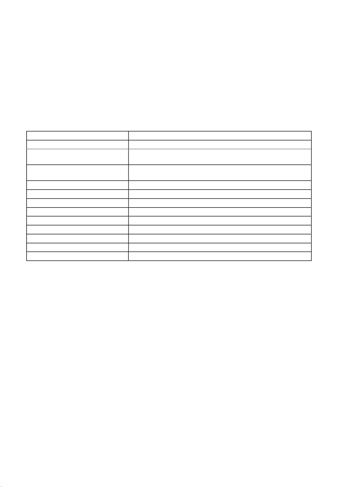
Specifications:
Card format Gen 2,
Card size
Max output resolution
Max number of cards per system
Graphic card memory 2GB total
Max current at +3.3V 0.25A (+1.8A when powering four channels of DPextend + DPadapt)
Max current at +12V 1.2A
Max Power 15 watts
Operating temperature 0 to 35 deg C / 32 to 96 deg F
Storage temperature -20 to 70 deg C / -4 to 158 deg F
Relative humidity 5% to 90% non-condensing
MTBF 180,000 hrs
Warranty 3 years
Page 4

4
XtremeVision-Pro+
The XtremeVision-Pro+ PCI Express graphics card supports the display of digital video capture windows. It is ideal for high end
video/ data walls, signage or display wall applications.
•
Gen 2, X16 lane PCI express graphics card
Digital outputs 4 x 2560 x 1600 x 32BITS/PIXEL @ 60Hz or 2 x 3840 x 2160 @ 30Hz
•
Low power
•
•
High Performance 2D and 3D graphics
•
High performance DMA image load (upto 2GB/S)
•
Support for Windows® 10 and Windows® 7
RGB, SD and HD video window support by adding the EMS XtremeVision-Pro+ range of capture cards.
•
HDCP is supported with EMS capture cards
•
•
Up to 16 cards (64 display channels) per system using the XDDM Driver on Windows 7 and up to 12 cards (48 display
channels) using the WDDM Driver on Windows 7 and Windows 10
Page 5

5
Installation
This section deals with installing XtremeVision-Pro+ cards and spreading the Windows desktop across all the screens. If
you are intending to use the XtremeVision-Pro+ cards with other EMS products, you should follow this section to get the
Windows desktop working correctly first.
System Requirements
•
A Pentium PCI Express bus computer with sufficient free PCIe slots.
At least 2GB of RAM, up to 8Gb for multiple cards
•
Support for Windows® 10 or Windows 7®
•
Unpacking
Your packing box should contain the following items:
The XtremeVision-Pro+ PCIe plug-in card.
•
4 x DVI Adapters (XtremeVision-Pro+/DVI only)
•
•
4 x HDMI Adapters (XtremeVision-Pro+/HDMI only)
It is recommended that all XtremeVision-Pro+ cards and any XtremeVision-Pro+ cards are installed in the system prior to
installing the drivers. Otherwise as cards are installed the drivers may need to be reinstalled as the card’s PCI bus numbers
change.
Note:
All plug-in cards are static sensitive and packed in antistatic materials. Please keep the card in its packaging until you are
ready to install.
It is recommended that you do not discard the packing box until you are completely satisfied with the XtremeVision-Pro+
card, and it is fully installed and working correctly. We also recommend that you make note of the serial number of the
card in a prominent place before you plug the card into the computer. This should hasten any query should you need to
contact us
Technical Support Department. The serial number is displayed on the card and the box label.
Power down the PC (including peripherals), switch off at the mains and disconnect all the cables connected to the
•
computer, noting the positions for accurate reconnection. Remove the PC cover.
Locate a vacant PCIe slot for the XtremeVision-Pro+ on the motherboard and remove the backing plate (retain all screws).
•
•
Remove the card from its packaging and secure it firmly into the empty PCIe slot. Extreme care should be taken when
securing the card into the slot as some motherboards may have components that impede the siting of the card.
Screw the card bracket to the back panel of the PC and replace the cover.
Connect screens to all the outputs from the card. If there are other graphics devices in the system, connect screens to them
(even if you don’t intend to use all the outputs in your final configuration).
Switch all the screens on then switch the machine on. You should see the boot messages on one of the screens. The screen on
which the system will boot is dependent on how the system is configured and the motherboard BIOS. It is not possible to control
which of the XtremeVision-Pro+ outputs the system will boot on.
Page 6

6
Installing the Display Drivers
Once the XtremeVision-Pro+ card has been installed and the boot messages are appearing on the correct monitor, you can start
Windows.
The Found New Hardware Wizard will announce that new hardware has been found. Do not use the Found New Hardware
Wizard to install the XtremeVision-Pro+ drivers. Install the XDDM or the WDDM display drivers from the Software Installation
Media supplied with the XtremeVision-Pro+ card.
If your final configuration has less than four screens select the number of screens required, otherwise select four screens.
Restart the machine.
When Windows starts up, the desktop should be spread over all the screens connected to the XtremeVision-Pro+.
Note:
The XtremeVision-Pro+ requires the EMS Display Driver Install V4.1.1 or later.
Multi Screen Drivers
XDDM
The XDDM Display Driver places the Windows desktop across all the screens connected to XtremeVision-Pro+ cards in the
system. XDDM is the legacy driver architecture used by graphics drivers from Windows 2000 through to Windows 7 and Windows
Server 2008 R2. It is not supported by Windows 10 or Windows Server 2012. The EMS XDDM drivers provide a robust,
multi-screen platform with advanced video capture and display capabilities.
The XDDM driver currently supports up to 16 XtremeVision-Pro+ cards (64 display outputs) in a single system.
WDDM
The WDDM Display Driver places the Windows desktop across the screens connected to the XtremeVision-Pro+ cards. WDDM is
the driver architecture used by modern Windows Operating Systems such as Windows 10. It aims to provide improved graphics
performance, additional functionality and operating system stability improvements.
The EMS WDDM driver currently provides support for up to 12 XtremeVision-Pro+ cards (48 display outputs) in a single system.
Page 7

7
Installing the Additional XtremeVision-Pro+ Cards
As the number of required screens increase, the likelihood of reaching a system limitation or encountering a problem increases.
The system limitations are the amount of address space available and the capacity of the power supply.
Please consult EMS support if you have any problems installing multiple cards.
Power
The amount of current a power supply can deliver on each voltage rail is limited. Often there is also a limit on the total power.
Each XtremeVision-Pro+ card requires 0.25A at +3.3V and 1.2A at +12V.
You can calculate the amount of current and the amount of power required for the XtremeVision-Pro+ cards. For example, the
requirements for a
Current
+3.3V 4 x 0.25A =
+12V 4 x 1.2A = 4.8A
Power
( 3.3V x 1.0A ) + ( 12V x 4.8A ) = 60.9W
These are just the requirements for the XtremeVision-Pro+ cards; you must take into account the requirements of all the other
devices in the system.
16-
1.OA
system of XtremeVision-Pro+ cards are calculated as follows:
SCREEN
Page 8
8
Connecting up to 64 Screens
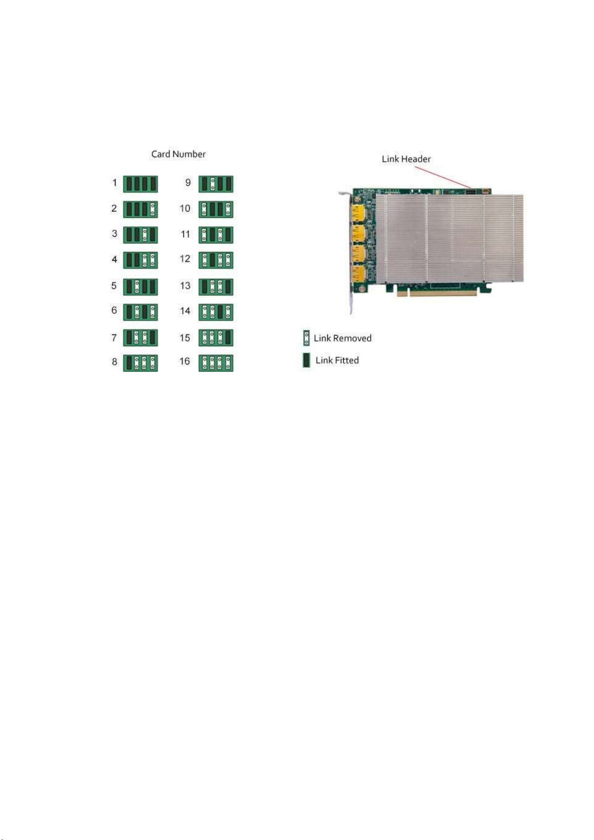
To connect up to 64 screens (XDDM Display Driver on Windows 7) or 48 screens (WDDM Display Driver on Windows 7 or
Windows 10) to XtremeVision-Pro+ cards,
Card Ordering
configure
the links as shown in the diagram below:
The links control the order in which the display driver uses the XtremeVision-Pro+ cards. Knowing the order in which the
XtremeVision-Pro+ cards are used is useful when connecting the screens and the outputs from video switches.
Note that if you have not configured your system to boot-up on on-board VGA graphics device or another plug-in VGA card the
system will boot-up on the master head of one of the XtremeVision-Pro+ cards but it is not possible to control which output will
be used, this is motherboard BIOS dependent.
If the WDDM driver is selected on installation, then an on board or third-party graphics adaptor must be configured as the boot
up display.
Insert the XtremeVision-Pro+ cards into the PCIe slots.
Connect the screens to the cards. The first card should be connected to the first group of four screens; the second should be
connected to the second group of four screens and so on.
Switch the screens on then switch the machine on.
Log on as a user with administrative access rights.
The Found New Hardware Wizard will announce that new hardware has been found. This will happen once for each slave
XtremeVision-Pro+ card you have added to the system. Do not use the Found New Hardware Wizard to install the XtremeVisionPro+ drivers.
Page 9
9
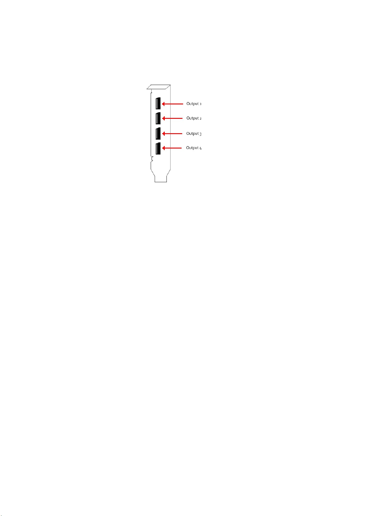
DisplayPort Outputs
The EMS XtremeVision-Pro+ has four DisplayPort connectors which allow full size, locking cables capable of driving next
generations displays. When used in conjunction with the EMS DPextend modules (powered via the XtremeVision-Pro+) cable
lengths of up to 40m can be achieved.
The XtremeVision-Pro+ outputs are numbered as follows:
Page 10
10
Display Driver Configuration Tool (DDCT)
(2)
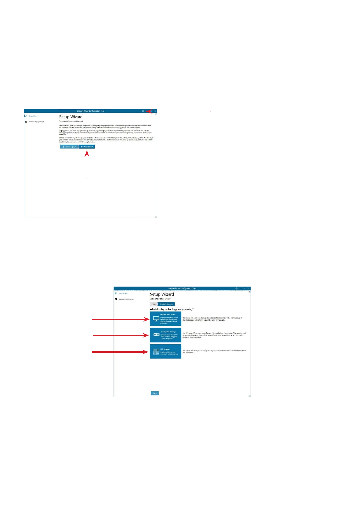
The DDCT Is a configuration tool designed to guide you through the design and creation of your video wall. The DDCT is
installed automatically as part of the driver install.
To access the DDCT, right click on your desktop, select Display Driver Configuration Tool then select the Set Up Wizard.
Alternatively select:
Start | Programs | EMS Drivers | Display Driver Configuration Wizar
(1)
It is recommended that you read the information on each page carefully.
Click on the “Information Icon” (1) to open a sliding window which gives version details and copyright information. The latest
version of the DDCT is available to download from the EMS website.
To commence your wall
Display Technology
Select the type of displays being used on your wall:
configuration,
(3)
(4)
(5)
click on “Start Wizard” (2). “Import Layout” is covered later.
•
Displays With Bezels – Monitors, TV’s and DLP Cubes. (3)
•
Overlapable Displays – Projectors (4)
•
LED Displays. (5)
Click on “Continue”.
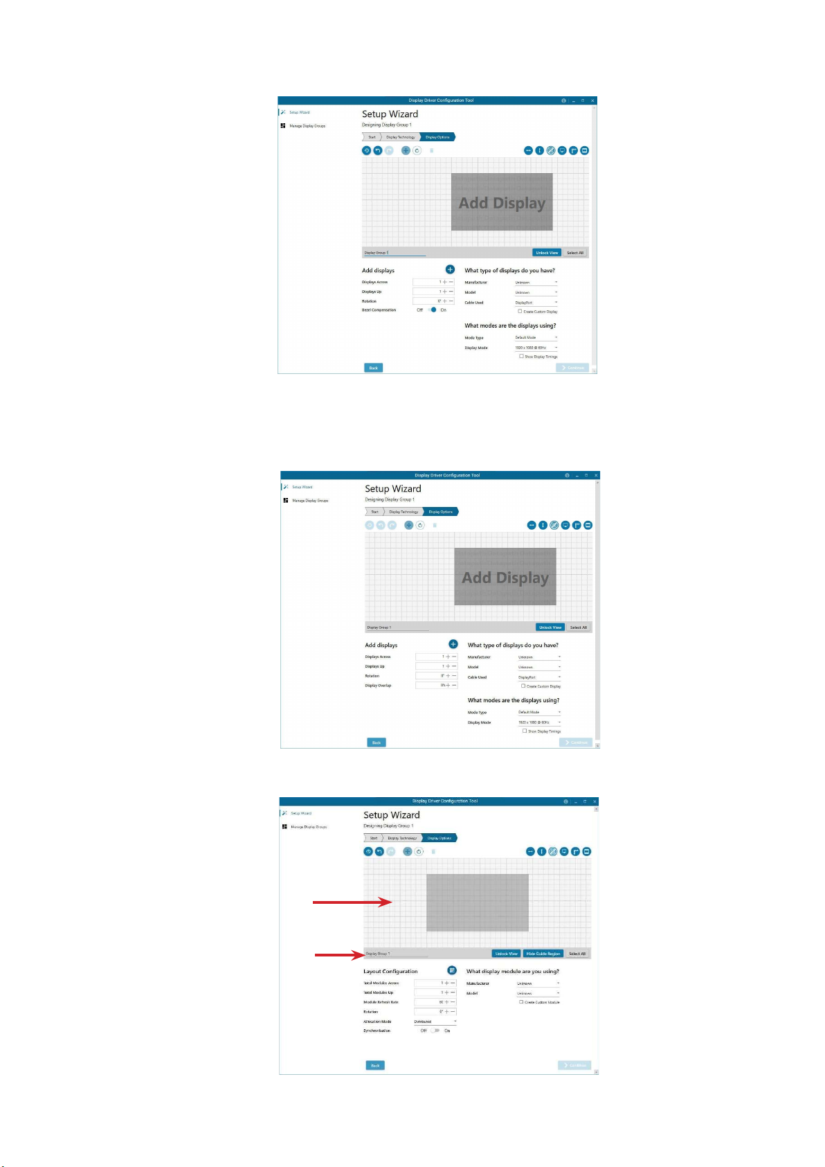
The tool will then display a configuration page for the type of display you selected;
Page 11
11
Displays with Bezels
(6)
(7)
Overlapable Displays
LED Displays
Page 12
12
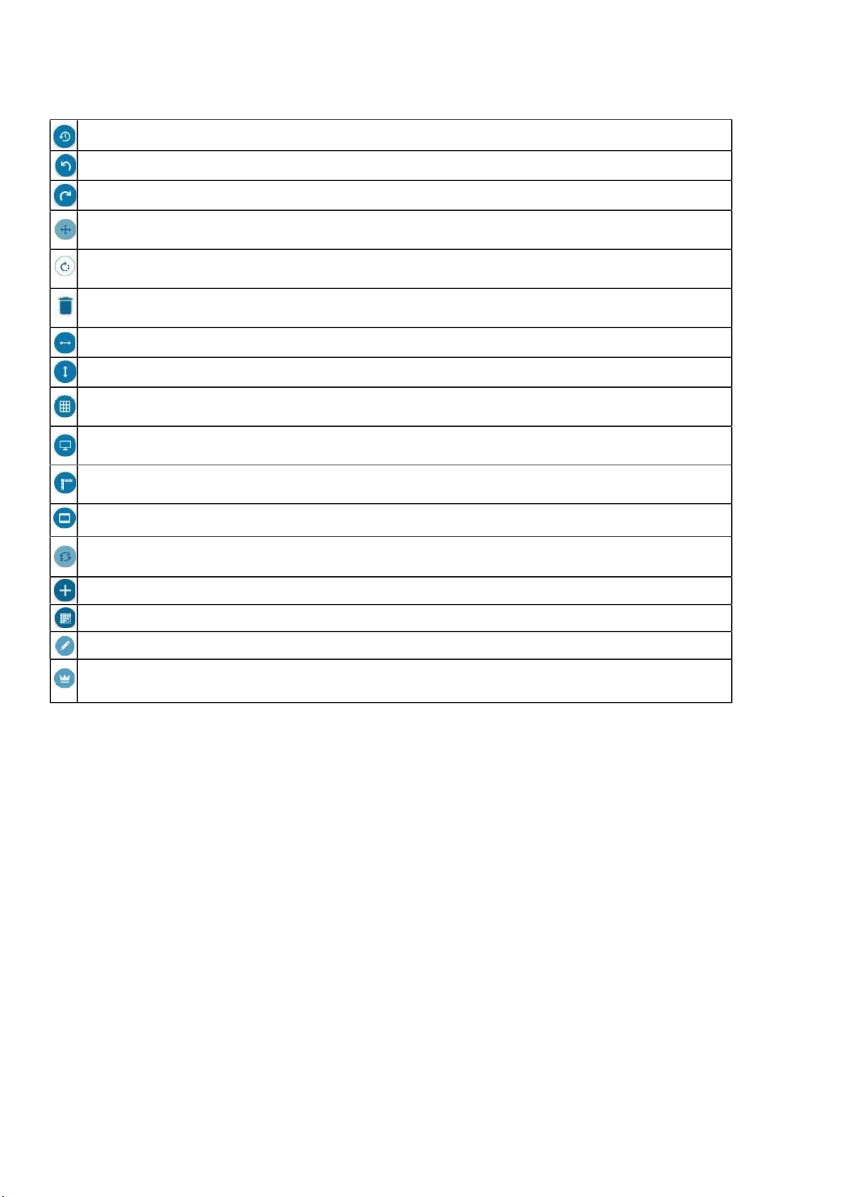
Application Tools
The application tools enable the user to manipulate the design of the wall. The table below describes the tool
functionalities
Undo All – Undo all commands made on this page.
Undo – Undo the last command.
Redo – Redo the last command.
Move displays – When selected, move the displays by clicking on and dragging the displays around the
representation.
Rotate displays – When selected click on a display and drag the cursor up or down, left or right to rotate the
display. The display can be rotated 90, 180 or 270 degrees.
Delete displays/Display Groups – Select the displays you wish to remove from the layout then click on the
delete button to delete all those selected.
Enable X Axis – Enables the display to be moved from left to right, and right to left.
Enable Y Axis – Enables the display to be moved up and down
Snap to Grid – When selected, if a display is dragged and released it will snap and position itself to the nearest
grid line.
Snap to displays – When selected, if a display is dragged close to another display and released, it will snap and
position itself to the display.
Snap to Guides – When selected, if the display is dragged and released near to the axis of another display it will
position itself on the same axis.
Show Display Bezels – Select to show or hide the bezels on all the displays in the representation.
Configure Outputs - Available in the Manage Display Group dialogue. Select an output and configure its
properties.
Add Button- Used to add displays to your group or to create a new group.
Layout Configuration - Used to add LED modules to your group or to create a new group.
Edit - Used to edit a selected Display Group
Primary Display - Indicates which display within the display group is the primary display/boot screen. If more
than one group is available, the Primary Display can be assigned to either group.
Representation
The representation grid (6) displays the physical arrangement of the wall as it is being created. Displays can be arranged
as required by clicking and dragging them to their required positions using the application tools.
Wall Naming
Click on the edit box (7) to allocate a name to your wall (optional but recommended). This will be used if you choose to export
your layout in the future.
Unlock View
When unlocked, the wall representation can be dragged to a preferred position using the mouse. Use the mouse wheel to zoom
in and out of the representation.
Select All
Choosing “Select All” enables the user to select all the displays on the representation to apply common attributes to all displays.
Page 13
13
Add Displays
Add displays is available for displays with bezels or overlapable displays. It enables you to configure the layout of your wall or
display group. Use the “Displays Across” and the “Displays Up” to create a plan of your layout. Once your layout has been
created you can then configure the displays using “What Type of Displays Do You Have?” When using overlapable displays
“Display Overlap” becomes available enabling you to select a percentage of overlap between displays.
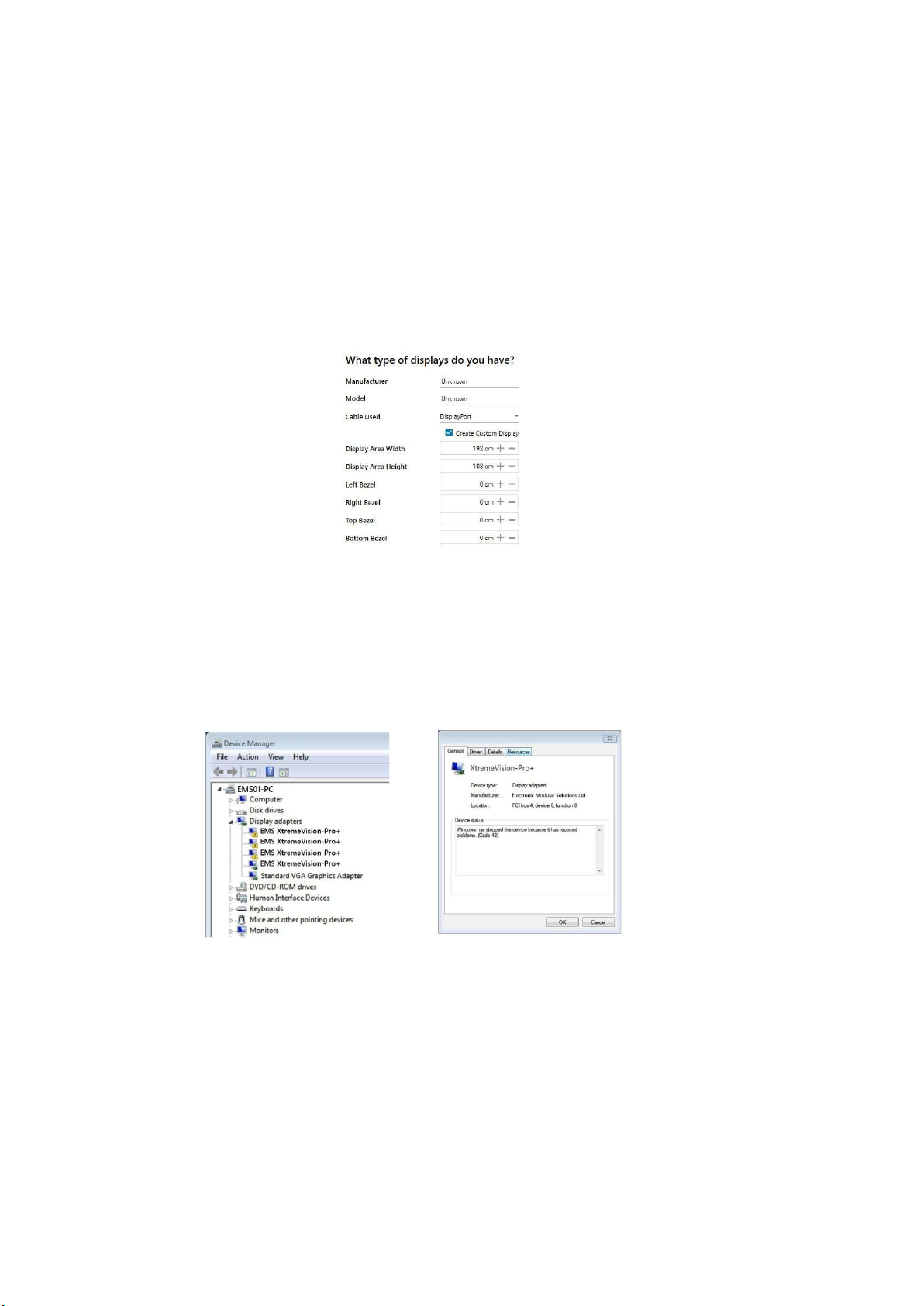
What Type of Displays Do You Have?
Displays with Bezels and Overlapable Displays
The first step to creating your wall is to select the type of displays you have. Use the “Manufacturer” and “Model” dropdown
lists to select each display you are using on your wall. The DDCT has an extensive database of displays, however if your display
is not contained in the list, you can input its details manually by selecting “Create Custom Display”.
Non Standard Device Reporting - XDDM Driver
The Device Manager will report all but one of the XtremeVision-Pro+ cards as non standard, displaying a warning next to each
card and an error code 43 in the device properties dialogue:
All the cards in your system are driven together to display a single, virtual desktop across multiple screens. Users should be
aware that although error code 43 is reported, this is in fact normal operation and there are no faults with the XtremeVisionPro+ cards installed in your system.
If the WDDM driver is installed no error is reported and all devices will be displayed as running correctly.
Page 14

14
Technical Support
Registered users can access our technical support line using, email, and the Support page on the EMS Web Site, usually with a response within
24 hours (excluding weekends).
Via Email
Send an email to [email protected] with as much information about your system as possible. To enable a swift response we need
to know the following details:
•
Specification of the PC - including processor speed
•
Operating System
Application Software
•
EMS Hardware / Software
•
•
The exact nature of the problem - and please be as specific as possible.
Please quote version and XtremeVision-Pro+ numbers of hardware and software in use wherever possible.
Electronic Modular Solutions Limited
Leicestershire
United Kingdom
Tel: +44(0)116 2775730
Email: [email protected]
Page 15

15
Index
A
Add Displays 14
Additional XtremeVision-Pro+
Cards 9
C
Card format 5
Card Ordering 10
Card size 5
Configure
Configure
Create Custom Display 15
Current 9
D
DDCT 12
Device Manager 15
Device properties 15
Digital outputs 10
Display Driver
Display Drivers 8
Display Overlap 15
DisplayPort connectors 11
Displays with Bezels 12
Display Technology 11
E
Enable X Axis 14
Enable Y Axis 14
Error code 43 15
G
Graphic card memory 5
L
Layout
LED Displays 12
M
Maximum current 5
Maximum number of cards per system 5
Maximum output resolution 5 Maximum
Power 5
Move displays 14
MTBF 5
Multi Screen Drivers 8
O
Operating Systems supported 6
Operating temperature 5
Overlapable Displays 12
Outputs 14
the links 10
Configuration
Configuration
Tool 11
14
P
Power requirements 8
Primary Display 14
R
Relative humidity 5
Representation 13
S
Specifications 4
Storage temperature 5
System Requirements 6
T
Technical Support 15
U
Unlock View 13
Unpacking 6
W
Wall Naming 13
Warranty 5
WDDM
X
XDDM Drivers 7
 Loading...