


-1-
MLS-202-C
100/95 Mbps
Two WAN VDSL2 (Long Reach Ethernet)
Ethernet Bridge
(Combo Interface For Copper or Coaxial)
User’s Guide
Version:1.0.E

--
I
COPYRIGHT
All rights reserved. No part of this publication may be reproduced, stored in a retrieval system,
or transmitted in any form or by any means, whether electronic, mechanical, photo copying,
recording or otherwise, without the prior written permission of the publisher.
FCC WARNING
This equipment has been tested and found to comply with the limits for a class B device, pursuant
to part 15 of FCC rules. These limits are designed to provide reasonable protection against
harmful interference in a commercial installation. This equipment generates, uses and can radiate
radio frequency energy and,
if
not installed and used in accordance with the instructions, may
cause harmful interference to radio communication. Operation of this equipment in a residential
area is likely to cause harmful interference, in which case, the user will be required to correct the
interference at the
user’s
own expense.
CE WARNING
This is a Class B product. In a domestic environment, this product may cause radio interference
in which case the user may be required to take adequate measures.
Take special care to read and understand all the content in the warning boxes:
Warning

--
I
INTRODUCTION
This modem is the LRE(Long Reach Ethernet) bridge that efficiently extends 10/100 Ethernet circuits
to 2 wire-Networking LAN for Internet or Intranet access. Over 915 meters(3,000feet) at 50Mbps using
existing phone wire. This modem will allow Ethernet connectivity in existing facilities without pulling
extra cable. This is perfect solution to Ethernet on the factory floor where systems have been upgraded
from slower serial communication to Ethernet networking. Installation is easy with a single switch setting.
One end is set for local and the other remote. This modem is used in phone wire to extend Ethernet
connectivity over existing phone grade phone wire.
Key Features
High-Speed 100/95Mbps communications link over existing phone line cable, Asymmetrical on LRE
50Mbps@ 915 meters(3,000feet), reach down to 20Mbps @ about 1.7Km(5,600feet)
Operates transparent to high layer protocols such as TCP/IP
Auto-MDIX and Auto-sensing 10Base-T or 100Base-TX and Full or Half-Duplex on the Ethernet
port
Plug and Play design for simple installation, single DIP switch for configuration.
Status LEDs for simple monitoring of the device and connection status
Point to Multi-Point Application(Extend Application)
HARDWARE INSTALLATION
--
I
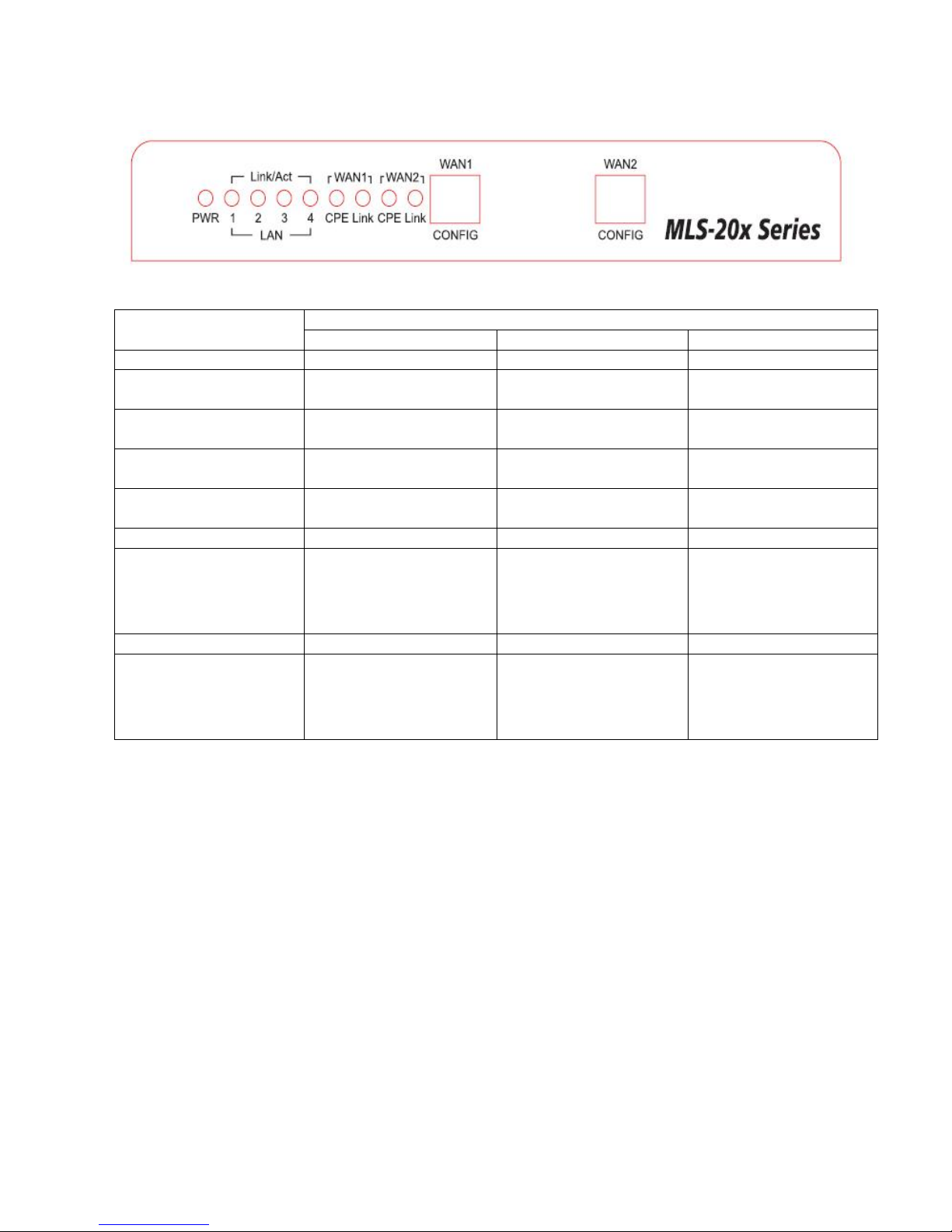
LED Indicators on the Front Panel
LED
Status
Glowing
Dimming
Flashing
POWER
DC 12 power feeding in
Not powered
N/A
LAN1 Link/Act
LAN1 Link
Disconnected or Link
failed
Received or Transmit
LAN2 Link/Act
LAN2 Link
Disconnected or Link
failed
Received or Transmit
LAN3 Link/Act
LAN3 Link
Disconnected or Link
failed
Received or Transmit
LAN4 Link/Act
LAN4 Link
Disconnected or Link
failed
Received or Transmit
WAN1 LINE CPE
CPE side Mode
CO side Mode
N/A
WAN1 LINE Link
VDSL2 Link
N/A
Slow Flashing mean
Link failed or Fast
Flashing mean
Received or Transmit
WAN2 LINE CPE
CPE side Mode
CO side Mode
N/A
WAN2 LINE Link
VDSL2 Link
N/A
Slow Flashing mean
Link failed or Fast
Flashing mean
Received or Transmit

--
I
Ports on the Real Panel
Port Name
Type
Functions
DC IN
DC 12V
Connects to the power adapter plug.
LAN1
RJ45
Connects to Ethernet port on FTTx/xDSL Modem or Switch for Internet
Access.
LAN2
RJ45
Connects to Ethernet port on FTTx/xDSL Modem or Switch for Internet
Access.
LAN3
RJ45
Connects to Ethernet port on FTTx/xDSL Modem or Switch for Internet
Access.
LAN4
RJ45
Connects to Ethernet port on FTTx/xDSL Modem or Switch for Internet
Access.
WAN1 Coax
Coax
Connects to Coaxial Cable or connects to VDSL2 devices.
WAN1 LINE
RJ11
Connects from wall outlet LINE in or connects to VDSL2 devices.
WAN2 Coax
Coax
Connects to Coaxial Cable or connects to VDSL2 devices.
WAN2 LINE
RJ11
Connects from wall outlet LINE in or connects to VDSL2 devices.

--
V
MODEM CONFIG SETTING
CONFIG
DIP1
(Side)
DIP2
(Interleave
protection )
DIP3
(Band plan or Rate
limit )
DIP4
(SNR margin)
ON
CPE
Fast
100/60
6dB
OFF
CO
Interleave
100/95
9dB
Recommend CONFIG Setting
CO[Master]
CONFIG
DIP1
DIP2
DIP3
DIP4
OFF
ON
OFF
ON
CPE[Slave]
CONFIG
DIP1
DIP2
DIP3
DIP4
ON
ON
OFF
ON
Essential Hardwares
Items Included
Description
Purpose
VDSL2 Ethernet Bridge modem
Main Unit
DC 12V Power Adapter
Connects from Power Port of the
main unit into a wall outlet

--
V
Hardware Connections
The figure about shows how to connect a xDSL modem to a phone line network. Follow the same
steps to connect and Ethernet device such as HUB or AP, to a phone line network.
Now you should have connected the Ethernet port, Line port and the Power port to the
appropriate devices or lines. LED will be as:
POWER ON
LAN Link/Act ON
LINE Link/Act ON
For more information on LEDs, see section “LED Indicators on the Front Panel”

--
V
TROUBLESHOOTING
The Bride had been designed to be a reliable and easy to use connection device. Please refer to
the list below to aid in troubleshooting.
The Power (green) LED is off
Make sure the power adapter is properly plugged into a live electrical outlet.
The LAN(Ethernet) or Line Link/Act LED is off.
The Ethernet or LRE device to which you are connected should be powered on and
properly configured.

--
V
Specifications
Network Standards
IEEE802.3 10BASE-T, 10Mbit/s
IEEE802.3u 100BASE-TX, Fast Ethernet at 100Mbit/s, Auto-negoatiaton
IEEE802.3x Full Duplex and Flow Control
Protocol:
Transparent to higher layer protocols
Connectors
Fast Ethernet:Four RJ45 Connectors
RJ11:Two RJ11 Female Connectors,One for WAN1 Line,the other WAN2 Line
Coax:Two Coax Female Connectors,One for WAN1 DATA,the other WAN2 DATA
Transmission Speed and Distance
Within a distance of 300 meters maximum speed of 100/95Mbps
Up to 5,600 Feet (-176dBm/Hz Noise Floor)
Fast Ethernet Interface
10/100 Mbps
MDI/MDI-X Auto Crossover
Network Management
Diagnosis of DSL link function
Line SNR select
Line Interleave protect
CO/CPE side select able
Band Plan profile select able
Indicators
Power LED
LAN1 Link/Act LED
LAN2 Link/Act LED
LAN3 Link/Act LED
LAN4 Link/Act LED
WAN1 Line CPE/CO LED
WAN1 Line Link/Act LED
WAN2 Line CPE/CO LED
WAN2 Line Link/Act LED

--
I
Environmental Conditions
Operating Temperature :0℃ ~ 50℃ (32℉ ~ 122℉)
Storage Temperature: -10℃ ~ 65℃ (14℉ ~ 149℉)
Operating Humidity:10% ~ 90%,Non-condensing
Power Requirement
External Power Supply:12V/1A
Power Consumption:< 8 Watts
Emissions Compliance
FCC part 15 Class B, CE Mark
Ordering Information
MLS-200 : 1 WAN, 2 *10/100 TX Ethernet Extender over Copper Line
MLS-200-C : 1 WAN, 4 *10/100 TX Ethernet Extender over Copper/Coax Line
MLS-202-C : 2 WAN, 4 *10/100 TX Ethernet Extender over Copper/Coax Line
Contact Information:
Email: jack@ems5.com

--
X
Appendix (PHY Link Rate reference Table) using AWG26 Copper
Communication
distance(meter)
100M/95M
Profile Line rate
(Download Mbps)
100M/95M
Profile Line rate
(Upload Mbps)
100M/60M
Profile Line rate
(Download Mbps)
100M/60M Profile
Line rate
(Upload Mbps)
100
100
95
100
60
200
100
93
100
60
300
90
87
100
59
315
86.3
85.7
100
58
615
60.7
47.8
81.4
38.2
915
34.2
26.4
53.6
19.4
1215
26.1
20.3
37.3
8.2
1515
21.1
11.9
28.9
3.4
1615
19.4
8.6
25.5
2.3
1715
18.1
6
22.7
1.3
Appendix (PHY Link Rate reference Table) using RG59 Coaxial
Communication
distance(meter)
100M/95M
Profile Line rate
(Download Mbps)
100M/95M
Profile Line rate
(Upload Mbps)
100M/60M
Profile Line rate
(Download Mbps)
100M/60M Profile
Line rate
(Upload Mbps)
100
100
95
100
60
200
100
95
100
60
300
100
95
100
60
315
100
93
100
58
615
83
80
100
55
915
65
60
88
42
1215
40
50
70
29
1515
30
36
56
16
1615
25
34
51
14
1715
22
22
46
13
2000
18
20
31
9
 Loading...