

Page 1

EMS5-8MA-SWITCH
8 port 10/100/1000 Gigabit
Green Network
Managed Switch
User’s Guide
Page 2

I
COPYRIGHT
All rights reserved. No part of this publication may be reproduced, stored in a retrieval system,
or transmitted in any form or by any means, whether electronic, mechanical, photo copying, recording
or otherwise, without the prior written permission of the publisher.
FCC WARNING
This equipment has been tested and found to comply with the limits for a class B device, pursuant to
part 15 of FCC rules. These limits are designed to provide reasonable protection against harmful
interference in a commercial installation. This equipment generates, uses and can radiate radio
frequency energy and,
if
not installed and used in accordance with the instructions, may cause harmful
interference to radio communication. Operation of this equipment in a residential area is likely to
cause harmful interference, in which case, the user will be required to correct the interference at the
user’s
own expense.
CE
This is a Class B product. In a domestic environment, this product may cause radio interference
in which case the user may be required to take adequate measures.
Take special care to read and understand all the content in the warning boxes:
Warning
Page 3

II
TABLE OF CONTENTS
FCC WARNING ........................................................................... I
1.INTRODUCTION .......................................................................................................................................... 1
2.Key Features ................................................................................................................................................. 1
3.Getting Started .............................................................................................................................................. 2
3.1 Connect To EMS5-8MA-SWITCH Web pages .............................................................................. 2
3.2 Menu Description ............................................................................................................................... 3
3.3 Switch Panel Description ................................................................................................................. 4
4. Function Description ................................................................................................................................... 4
4.1 System ................................................................................................................................................ 4
4.1.1 Information .............................................................................................................................. 4
4.1.2 IP Setting ................................................................................................................................. 4
4.1.3 User Account ........................................................................................................................... 6
4.1.4 Port Setting ............................................................................................................................. 6
4.2 Configuration ...................................................................................................................................... 7
4.2.1 VLAN ........................................................................................................................................ 7
4.2.1.1 Static VLAN .................................................................................................................. 7
4.2.1.2 VLAN Setting ............................................................................................................... 8
4.2.1.3 Admin VLAN(option) ................................................................................................... 9
4.2.2 QOS........................................................................................................................................ 10
4.2.2.1 Port-based Priority ................................................................................................. 10
4.2.2.1 Queue Weight .......................................................................................................... 10
4.2.3 Service VLAN ....................................................................................................................... 11
4.2.3.1 TPID setting .............................................................................................................. 11
4.2.3.2 Uplink Port Setting ................................................................................................. 12
4.2.3.3 Static Service VLAN ............................................................................................... 12
4.2.4 IGMP ...................................................................................................................................... 13
4.2.5 Trunk Group Setting ............................................................................................................. 14
4.2.6 Loop Prevention ................................................................................................................... 15
4.2.7 Port-based Mirroring ............................................................................................................ 16
4.2.8 Port Isolation ......................................................................................................................... 17
4.2.9 Bandwidth Control ................................................................................................................ 18
4.2.10 Jumbo Frame ..................................................................................................................... 19
4.2.11 MAC Constraint .................................................................................................................. 20
4.2.12 Green Ethernet ................................................................................................................... 21
4.2.13 EEE ...................................................................................................................................... 22
4.2.14 SNMP ................................................................................................................................... 23
4.2.15 Provision(option) ................................................................................................................ 23
4.3 Security ............................................................................................................................................. 24
4.3.1 MAC Address ........................................................................................................................ 24
Page 4

III
4.3.1.1 MAC Search ............................................................................................................. 24
4.3.1.2 Static MAC ................................................................................................................ 25
4.3.2 Storm Control ........................................................................................................................ 26
4.4 Monitoring ......................................................................................................................................... 27
4.4.1 Port Statistics ........................................................................................................................ 27
4.4.2 Cable Diagnostic .................................................................................................................. 28
4.5 Tools .................................................................................................................................................. 29
4.5.1 Firmware Upgrade ............................................................................................................... 29
4.5.2 Configuration Backup .......................................................................................................... 29
4.5.3 Reset ...................................................................................................................................... 30
4.5.4 Save ....................................................................................................................................... 30
4.5.5 Reboot ................................................................................................................................... 30
5. Contact Information
.................................................................................................................................. 38
Page 5

1
1.INTRODUCTION
This Layer 2 Gigabit Managed Switch is a perfect solution for young and dynamic Offices with small
network user groups. bridge that efficiently extends 10/100/1000 Ethernet circuits to user side Networking,
LAN side for Internet and Intranet access. The document is user guide for EMS5-8MA-SWITCH Green
Network Managed Switch. The EMS5-8MA-SWITCH acts as a web server to accept http connection request
and replies web pages so that user can get configuration or change configuration to EMS5-8MA-SWITCH by
web access.
2.Key Features
8 LAN gigabit non-blocking Managed switch.
Each port supports full duplex 10/100/1000M connectivity (half duplex only supported in 10/100 mode)
Full-duplex and half-duplex operation with IEEE 802.3x flow control and backpressure.
Support 9K bytes jumbo packet length forwarding at wire speed.
Support RJ45 Cable Test Function.
Support IEEE 802.1Q VLAN.
Support Loop Prevention configuration.
Support Quality of Service (QoS).
Support RFC MIB Counter.
Support Stacking VLAN and Port Isolation.
Support IEEE 802.1ad Stacking VLAN.
Support IEEE 802.3ad Link aggregation port group.
Broadcast/Multicast/Unknown Uni/Multicast storm control protects system from attack by hackers.
Support Green Ethernet features.(Link-On Cable Length Power Saving, Link-Down Power Saving)
Support EEE 802.3az
Page 6

2
3.Getting Started
3.1 Connect To EMS5-8MA-SWITCH Web pages
Connect the EMS5-8MA-SWITCH through http service, Typping the IP in the URL of browser. We suggest
using Mozilla Firefox(3.6 above) , Firefox to access the web of EMS5-8MA-SWITCH. In the first, the
default IP is static IP setting.
192.168.172.2 and the net-mask is 255.255.255.0. Please configure the IP and net-mask of your host
correctly to access the EMS5-8MA-SWITCH web pages.
If you connect to EMS5-8MA-SWITCH successfully, you will see an authentication dialog. Please enter
“admin” @ username and “12345” at password to login.
Figure: 3.1
After you login in the web page successfully, you will see the Product information page. This page show
some information of this EMS5-8MA-SWITCH device. The upper frame is the front panel frame, which
Page 7
3
shows the connection situation of each port. If a port is linked up, the corresponding port on the front panel
will be green, such as LAN2 port on Figure 3.1
3.2 Menu Description
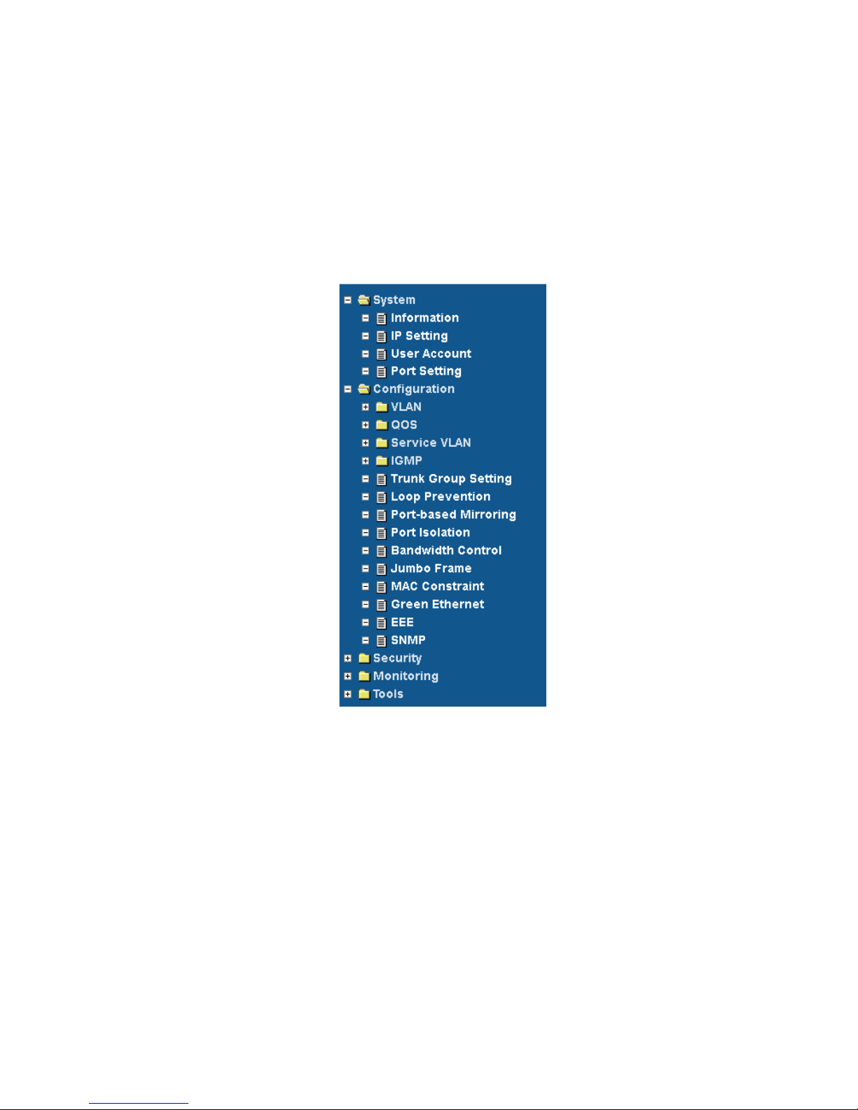
The left panel shows the configuration that user can access through web pages. Some configuration web
pages are hidden by the group label. To expand the group label, click the plus sign on the left side of group
label.
Figure: 3.2
Page 8

4
3.3 Switch Panel Description
The top panel shows the Switch connect status for operator can access through web pages and know the
Switch status.
Panel had three type define,
3.3.1 “Green.” mean normal connector
3.3.2 ”Black” mean disconnect
3.3.3 “Yellow” mean Loop port Provision block port
Figure: 3.3
4. Function Description
User can configure EMS5-8MA-SWITCH through web pages, such as VLAN entry, IP setting. In this section,
configuration that user can access through web pages will be introduced.
4.1 System
4.1.1 Information
This page shows the EMS5-8MA-SWITCH configuration such as Ethernet Address, IP address and firmware
version.
Figure: 4.1.1
4.1.2 IP Setting
This page shows IP configuration. User can set static IP address, or enable DHCP client function to get IP.
Page 9

5
Figure: 4.1.2
Note:
a.)The Default IP Address Setting is Static IP setting.
Page 10

6
4.1.3 User Account
This page shows username and password configuration. User can change username and password in this
page.
Figure: 4.1.3
Note:
a.)The Default Login User: admin
b.)The Default Password : 12345
4.1.4 Port Setting
This page shows link status, speed, duplex, and flow control ability of all ports. User can change port ability
of switch in this page.
Figure: 4.1.4
Page 11

7
4.2 Configuration
4.2.1 VLAN
4.2.1.1 Static VLAN
This page shows information of static VLAN entries. User can add/remove static VLAN entries in this page.
Figure: 4.2.1
Parameter
Description
Member
The Port is a member of the specified VLAN and the frames of this VLAN can
be switched through this port, but the tagging information in the frame header
is not modified by the Switch.
Untagged
The port is an untagged port (as defined in 802.1Q) that is participating in the
VLAN. In such an untagged port the Switch will strip off the 802.1Q tag from
the incoming and outgoing frames if they are tagged in such a way. This is
used for sending frames to non-802.1Q-compliant devices.
Tagged
The port is a tagged port (as defined in 802.1Q) and is participating in the
VLAN. The Switch will put the VLAN information of the port – including VID
and Priority – into the header of the untagged frames coming in or transmitted
from the port. The tagged VLAN information in the frames can later be used
by other 802.1Q-compliant devices for forwarding decisions.
Not Member
The port is not participating in the VLAN as identified by the selected VID(VLAN ID).
Note:
a.) Default VLAN with VIS being “1” cann’t be removed.
Page 12

8
4.2.1.2 VLAN Setting
This page shows VLAN port information. User can assign PVID, tag egress mode, accepted frame type of
each port.
Figure: 4.2.2
Parameter
Description
PVID
Default PVID=1, User can assign new PVID for setting.
Set the VLAN ID. The limit is 1 to 4095. The VLAN ID is assigned to all
untagged frames received on this port.
Mode
(Tag Egress mode)
Tag Egress mode, accepted frame type of each port.
Original: - Output frame will follow VLAN untag setting.
Keep-format: - Output frame will keep original(VLAN or Un-Tag) format.
Priority-tag: - Output frame will be priority tag(Output frame is tagged with
VID=0).
Page 13

9
4.2.1.3 Admin VLAN(option)
This page shows Administrator VLAN for CPU port. User can assign PVID, tag, accepted
management frame to CPU port.
Figure: 4.2.3
Note:
a.) Enable Admin VLAN will be apply to SNMP, Web, and ping etc. service.
Page 14
10
4.2.2 QOS
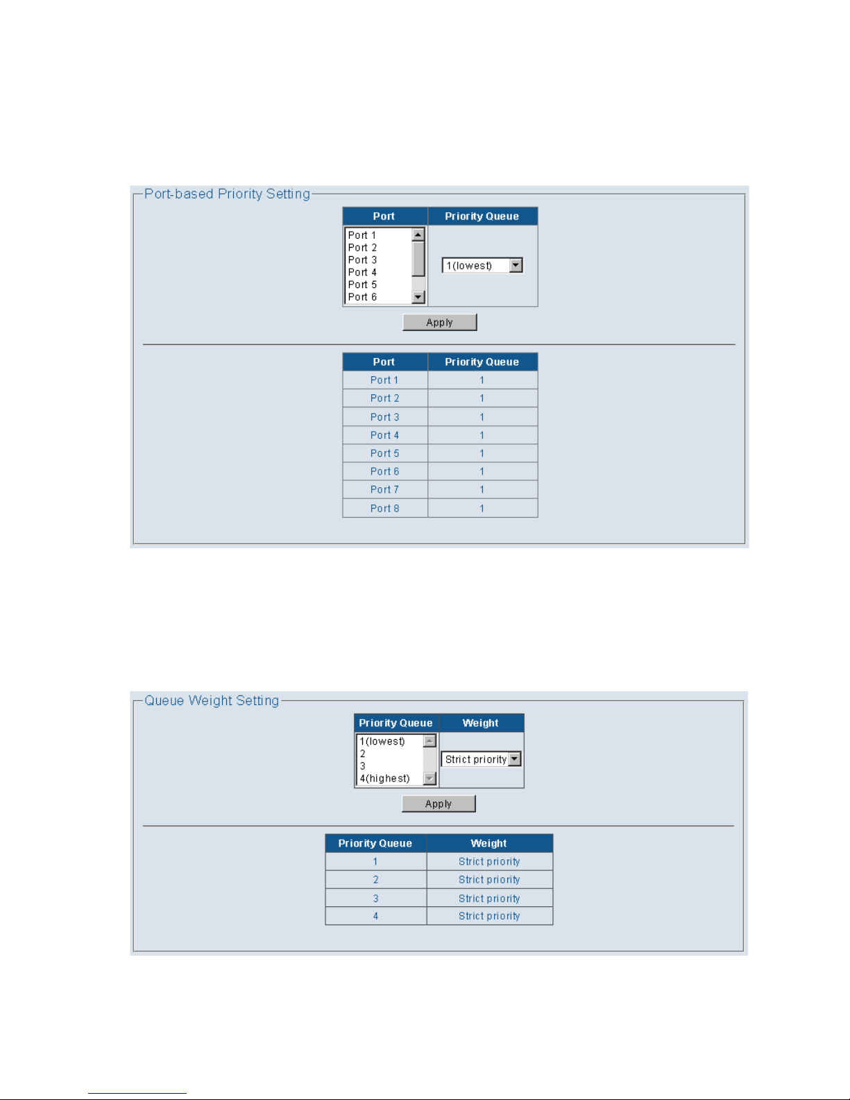
4.2.2.1 Port-based Priority
This page shows port-based priority of each port. User can configure port priority with 4 priority level
of each port.
Figure: 4.2.4
4.2.2.1 Queue Weight
This page shows the priority to queue mapping. User can set the sixteen priority to queue mapping
of each priority.
Figure: 4.2.5
Page 15
11
4.2.3 Service VLAN
4.2.3.1 TPID setting
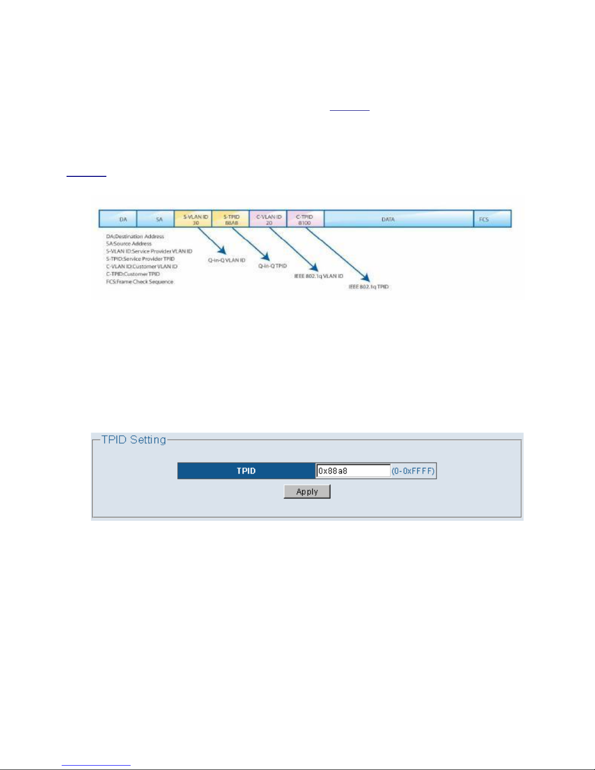
Tag protocol identifier (TPID). With the IEEE standard 802.1ad, double-tagging can be useful for
Internet service providers, allowing them to use VLANs internally while mixing traffic from clients that
are already VLAN-tagged. The outer (next to source MAC and representing ISP VLAN) S-VLAN Tag
(service VLAN tag) comes first, followed by the inner C-VLAN Tag (customer tag). In such cases,
802.1ad specifies a TPID of 0x88a8 for service-provider outer S-VLAN Tag.
Figure: 4.2.6
The device determines whether a received frame carries a service provider VLAN tag (S-VLAN Tag)
or a customer VLAN tag (C-VLAN Tag) by checking the TPID value. After receiving a frame, the
device compares the configured TPID value with the value of the TPID field in the frame. If the two
match, the frame carries the corresponding VLAN tag.
Figure: 4.2.7
Page 16
12
4.2.3.2 Uplink Port Setting
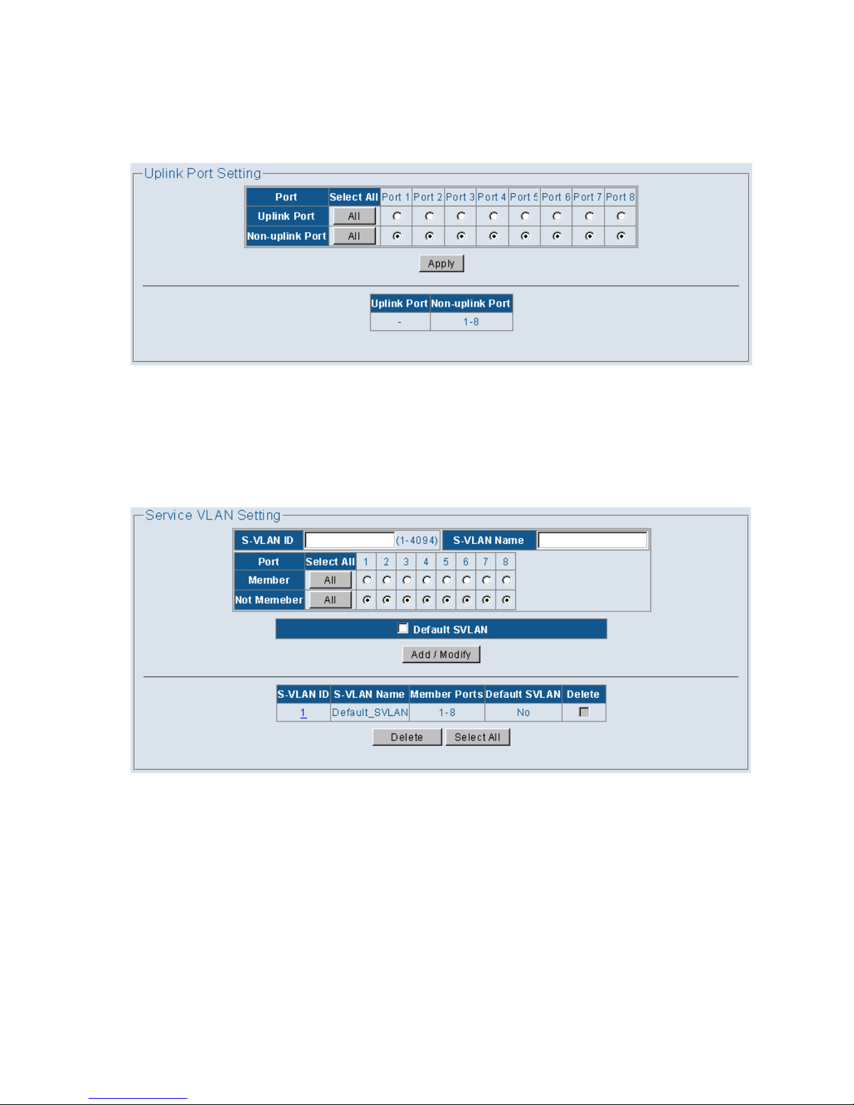
This page shows the device uplink port setting for handling Q-in-Q tag. User can set which port is
working for uplink port function.
Figure: 4.2.8
4.2.3.3 Static Service VLAN
This page shows information of Service VLAN entries. User can add/remove Service VLAN entries
in this page.
Figure: 4.2.9
Page 17
13
4.2.4 IGMP
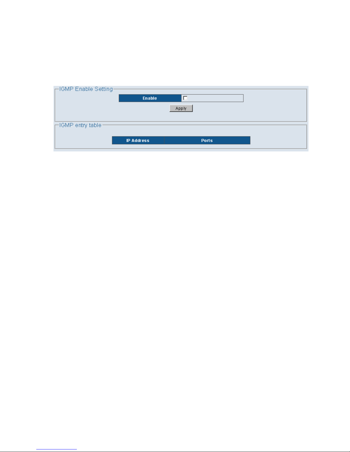
The IGMP menu is used for configuring IGMP snooping. IGMP means "Internet Group Management
Protocol". It is a protocol through which hosts can register with their local router for multicast services. If
there is more than one multicast router on a given sub- network, one of the routers is elected and assumes
the responsibility of keeping track of group membership.
Figure: 4.2.10
Page 18
14
4.2.5 Trunk Group Setting
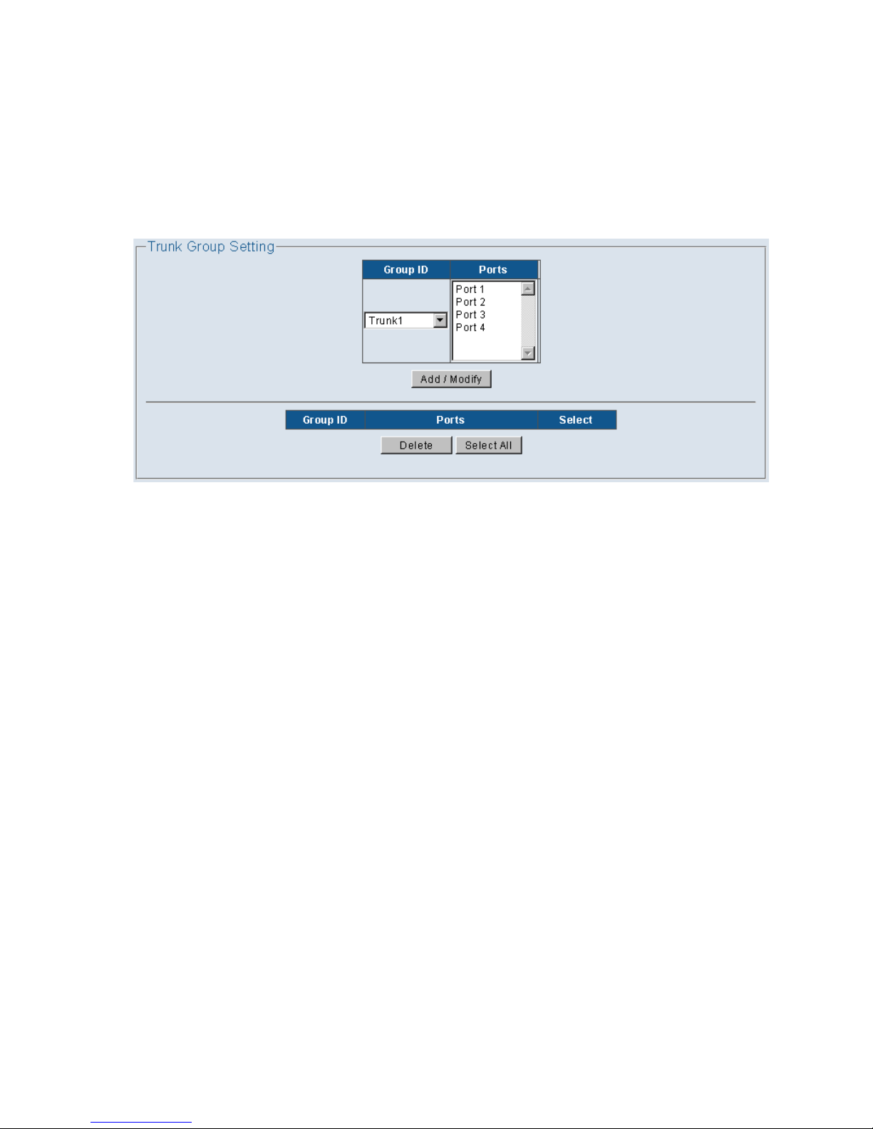
Port Trunking defines a network link aggregation and trunking method which specifies how to create a
single high-speed logical link that combines several physical links. Use the Trunk Configuration page shown
above to create trunk groups. The Switch supports a maximum of one trunk groups for 1000Mbps ports.
Each trunk group in groups may be comprised of up to four ports, selected from any combination of
1000Mbps ports.
Figure: 4.2.11
Page 19
15
4.2.6 Loop Prevention
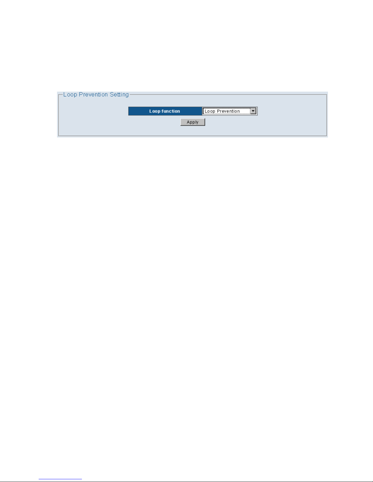
The EMS5-8MA-SWITCH supports loop prevention function that can detect and relieve a loop situation of
Ethernet network topology. As long as loop condition is detected, the switch blocks the port automatically and
starts to blink the port Link/Act LED to indicate which port has been blocked to relieve a loop. When a loop
condition disappears, the port Link/Act LED returns to normal port property state automatically.
Figure: 4.2.12
Page 20
16
4.2.7 Port-based Mirroring
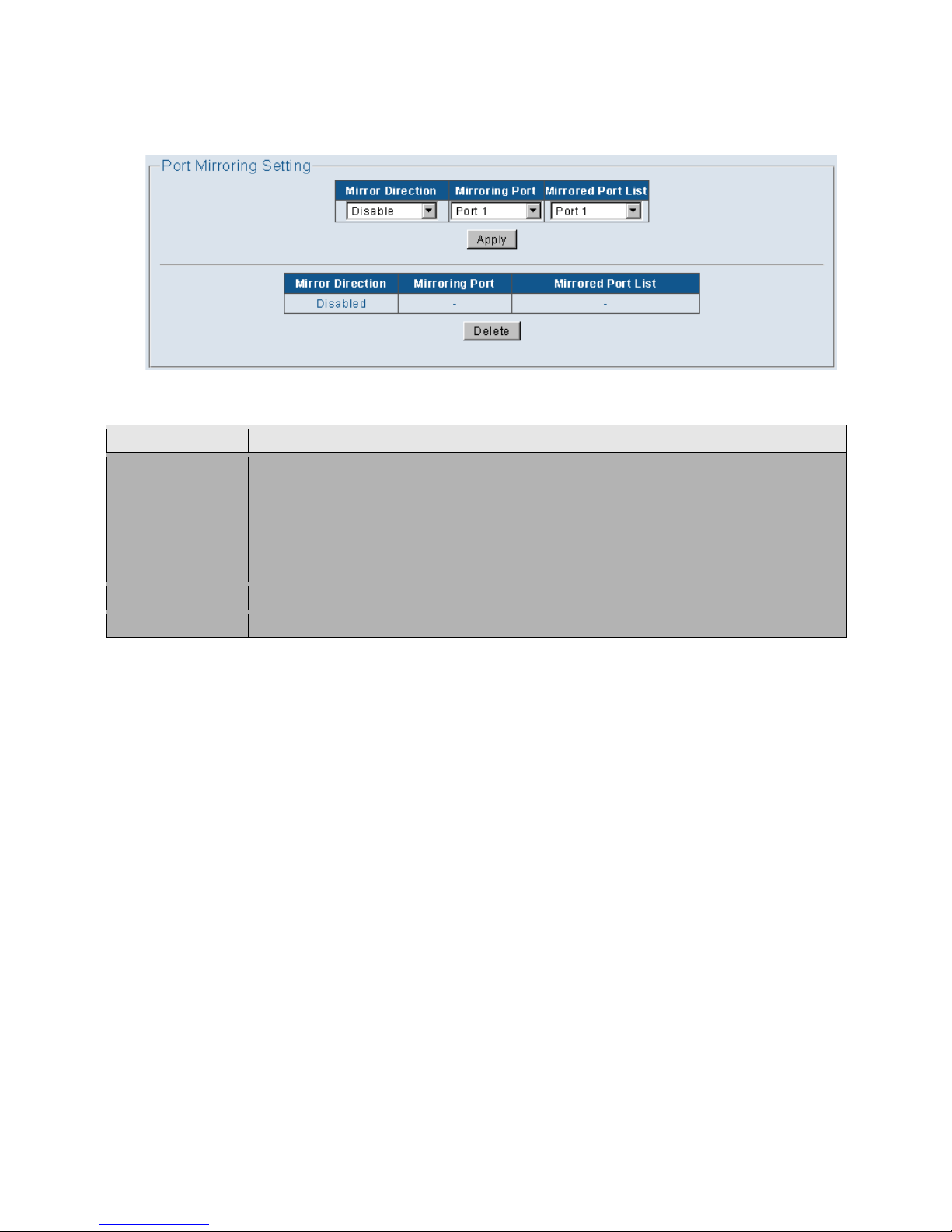
Set the port mirroring option to monitor data being transmitted through a specific port.
Figure: 4.2.13
Note:
Parameter
Description
Mirror Direction
Select appropriate mode
Disable: – Mirror mode is disabled
RX: – Monitor only incoming traffic
TX: – Monitor only outgoing traffic
Both: – Monitor both incoming and outgoing traffic
Mirroring Port
Select the port which will do the monitoring.
Mirrored Port List
Select the port that needs to be monitored.
Page 21
17
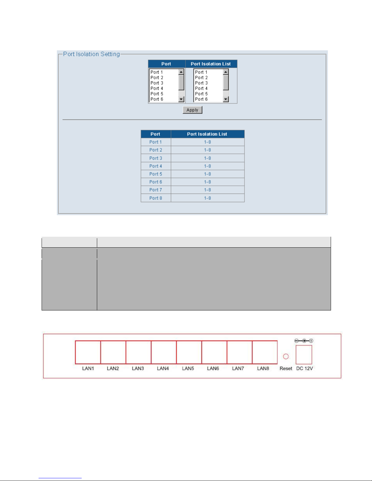
4.2.8 Port Isolation
This page shows the port isolation configuration. User can set isolation port mask of each port.
Figure: 4.2.14
Note:
Parameter
Description
Port
Select the physical port needs to be setting of Isolation.
Port Isolation List
The port is isolated. Isolated ports belonging to the same VLAN(even untag) do
not communicate with each other – this is generally set for security reasons.
The isolated ports communicate only with the up-link ports, which should NOT
be set as “isolated”.
1: LAN 1 port; 2: LAN 2 port ; 3: LAN 3 port; 4: LAN 4 port; 5: LAN 5 port..etc.
Example:
LAN1 : Port 1 is Up-link port
LAN2~8: Can link to LAN1 port
LAN2~8: Can't communication each other port ; setting can be reference follow
Page 22
18
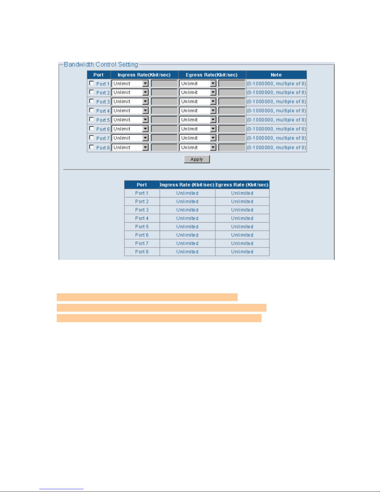
4.2.9 Bandwidth Control
This page shows the per port ingress/egress bandwidth control rate of each port.
Figure: 4.2.14
Note:
a.) before bandwidth setting, must select the port first.
b.) 1M = 1000k, 10M=10000k, 100M=100000k, 10000M=1000000k
c.) Apply only write to memory, Tools-save can write to CPU.
Page 23
19
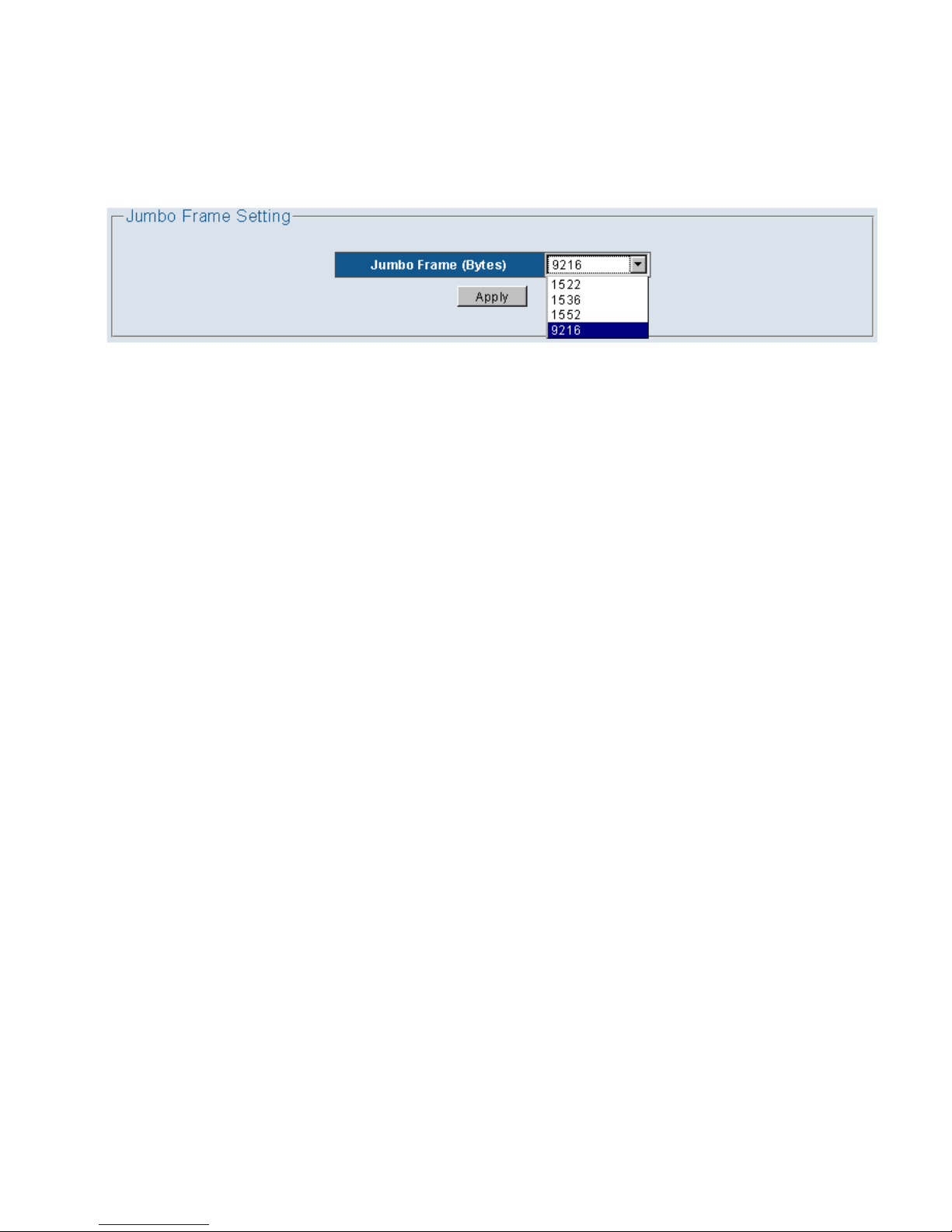
4.2.10 Jumbo Frame
This page shows the maximum transmission unit (MTU) size of packet that the switch can receive/transmit.
User can change the MTU configuration in this page. The default maximum Jumbo Frame support 9216
Bytes.
Figure: 4.2.15
Page 24
20
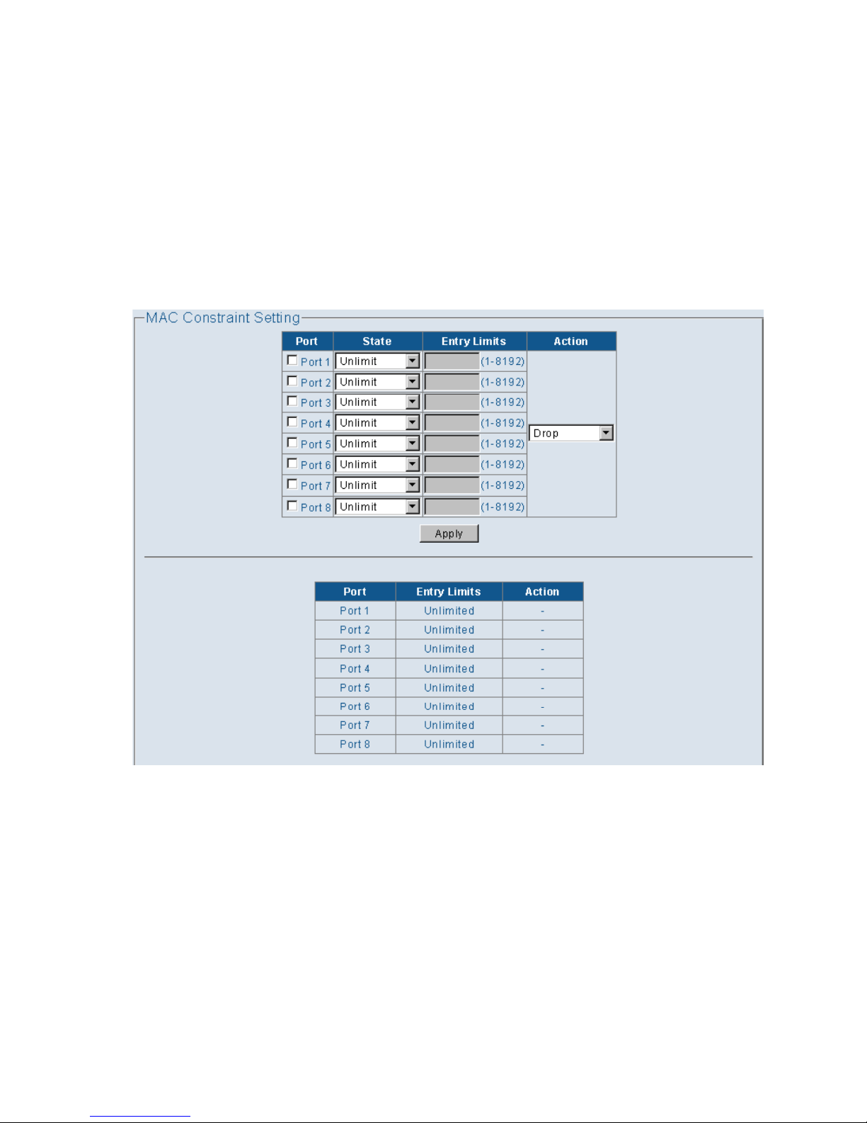
4.2.11 MAC Constraint
The “MAC Constraint” mean the MAC Limit Configuration”. This page menu lets the user limit the number of
incoming MAC addresses per port. If the user wants to disable this function, select “Disable” from the
combo box “Mac Limit Function” on the upper left. The Limit Quantity range is 1~8192 per port. The MAC
addresses learned are recorded on a per-port basis. Only the frames with such recorded MAC addresses will
be forwarded. This learning process will be conducted every three minutes. So, if users change the NIC of
the PC or IP appliance, the new MAC address will be learned in three minutes by the Switch, within the set
quantity limitations. The MAC Constraint Limit Function can be disabled or enabled per port, under the
parameter labeled “Action” in the table. Generally this function is only enabled for downlink ports.
Figure: 4.2.16
Page 25
21
4.2.12 Green Ethernet
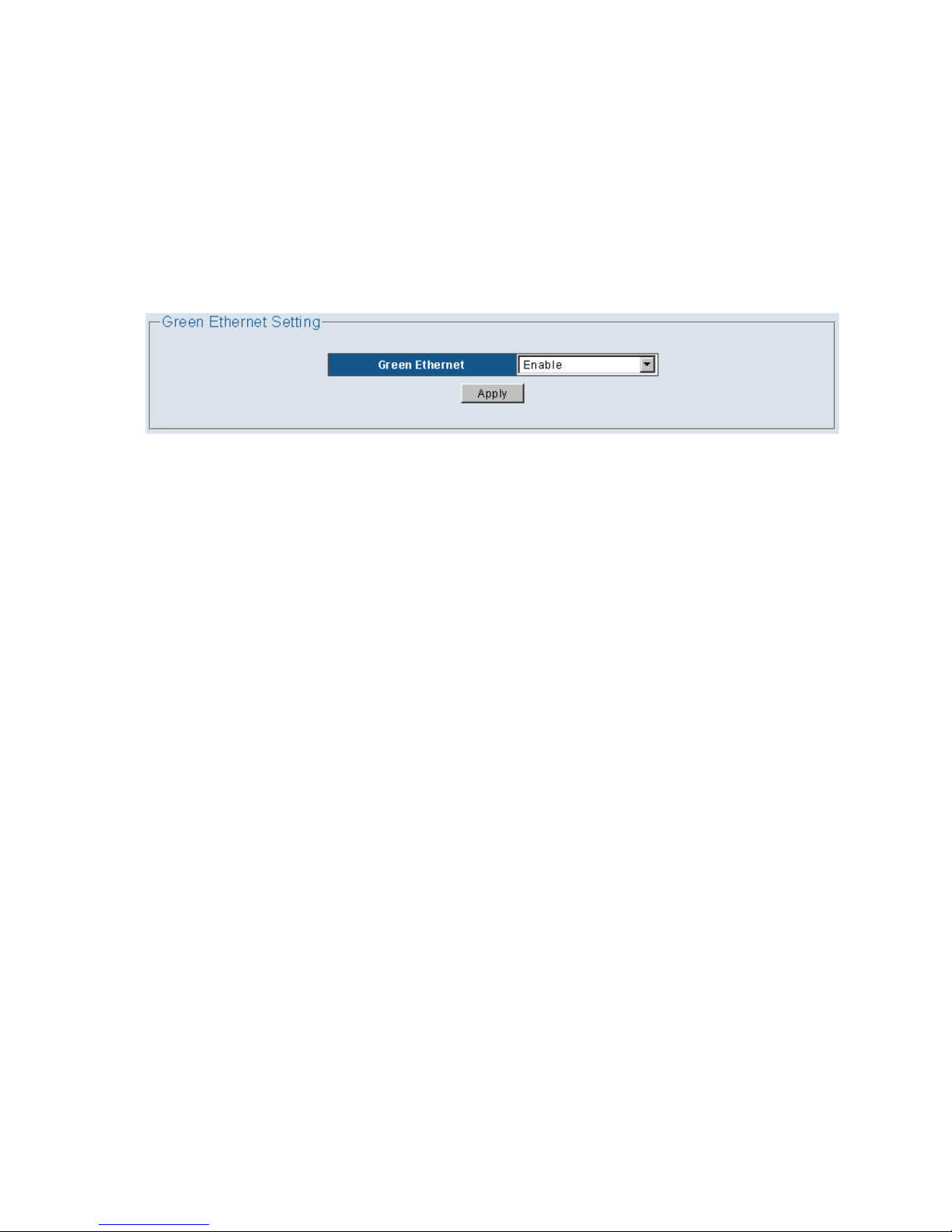
The EMS5-8MA-SWITCH provides link-on and dynamic detection of cable length and dynamic
adjustment of power required for the detected cable length. This feature provides high performance with
minimum power consumption.
The EMS5-8MA-SWITCH implements link-down power saving on a per-port basis, greatly cutting power
consumption when the network cable is disconnected. After it detects an incoming signal, it wakes up from
link-down power saving and operates in normal mode.
Figure: 4.2.17
Page 26
22
4.2.13 EEE
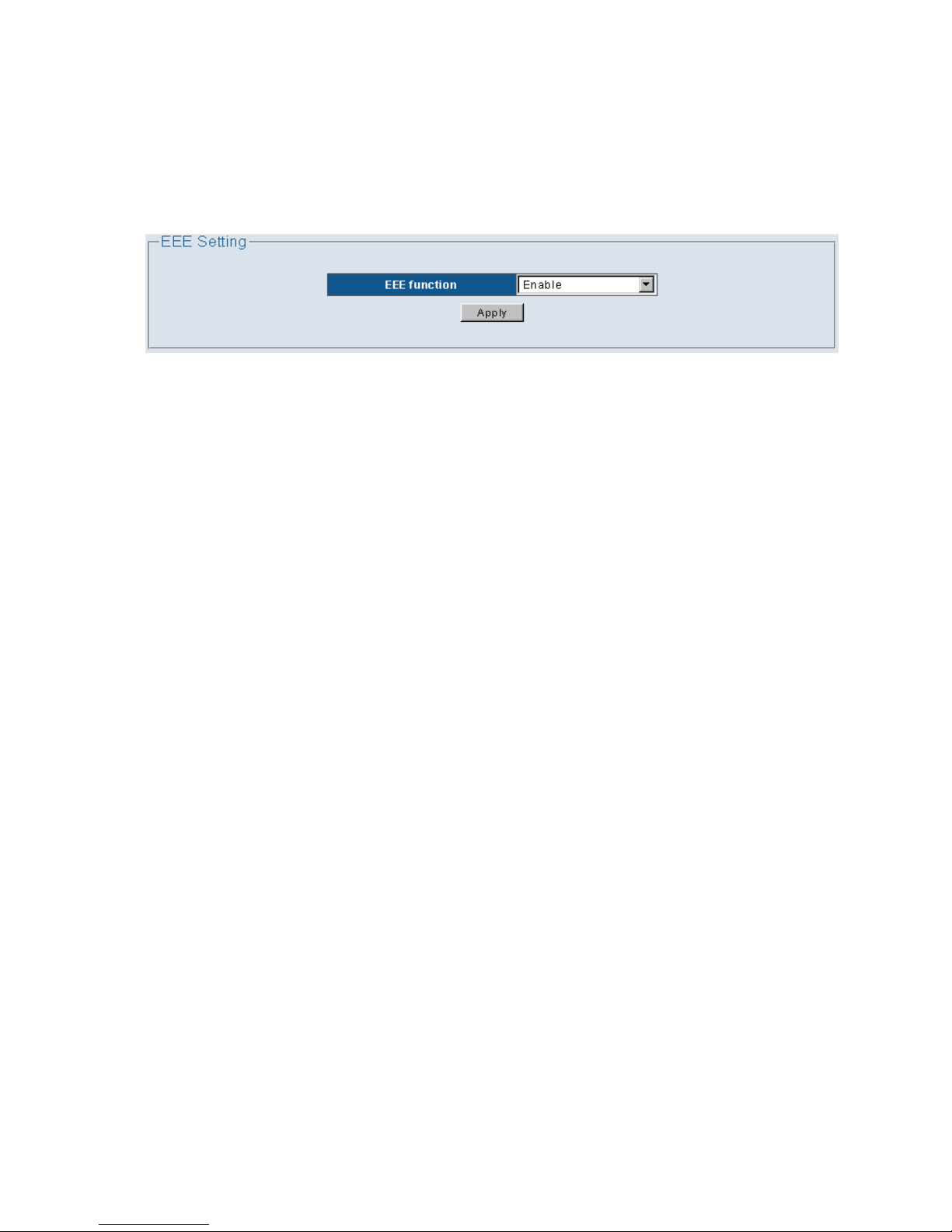
The Energy Efficient Ethernet (EEE) optional operational mode combines the IEEE 802.3 Media Access
Control (MAC) sub-layer with 100Bse-T and 1000Base-T Physical Layers define to support operation in Low
Power Idle mode. When Low Power Idle mode is enable, systems on both sides of the link can disable
portions of the functionality and save power during periods of low link utilization.
Figure: 4.2.18
Page 27
23
4.2.14 SNMP
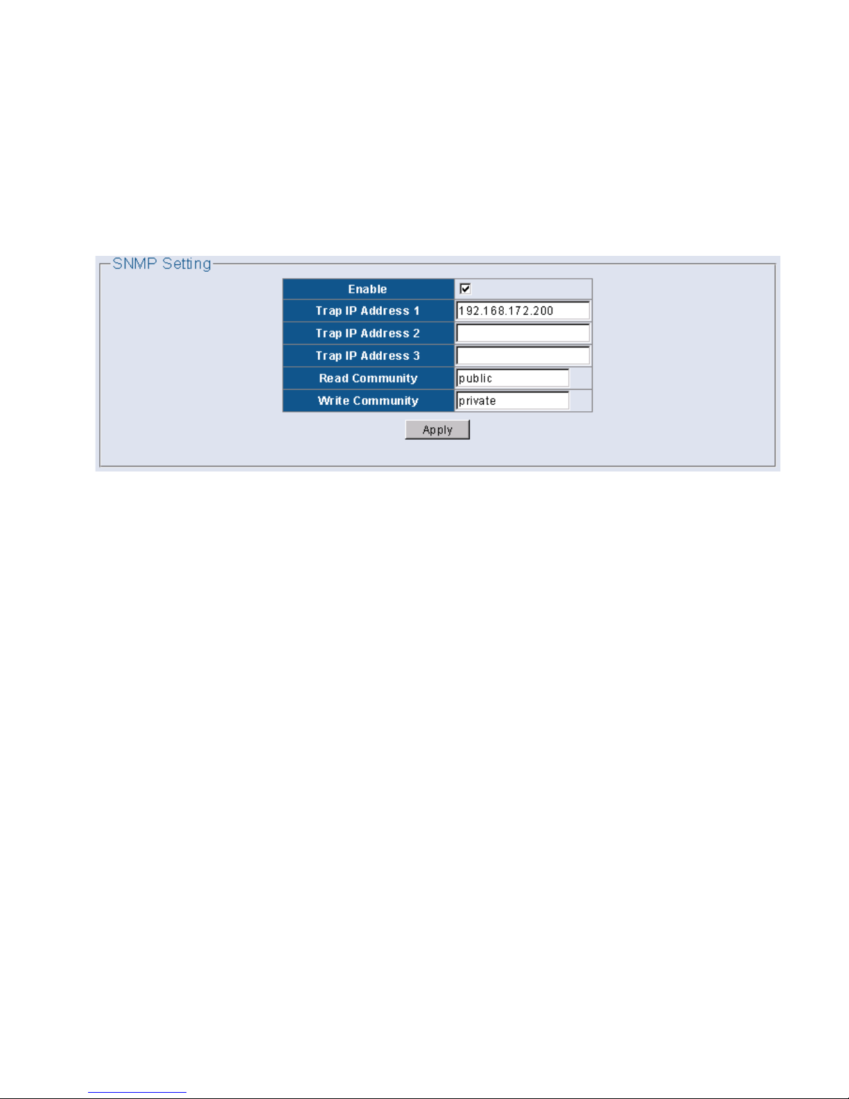
User can use an external SNMP-based application to configure and manage the switch. This management
method requires the SNMP agent on the switch and the SNMP Network Management Station to use the
same community string. This management method, in fact, uses two community strings: the Read community
string and the Write community string. If the SNMP network management station only knows the Write
community string, it can read and write to the MIBs (Management Information Bases of the devices), but, if
it only knows the Read community string, it can only read the MIBs.
Figure: 4.2.19
4.2.15 Provision(option)
This function only support ODM/OEM customer.
Page 28
24
4.3 Security
4.3.1 MAC Address
4.3.1.1 MAC Search
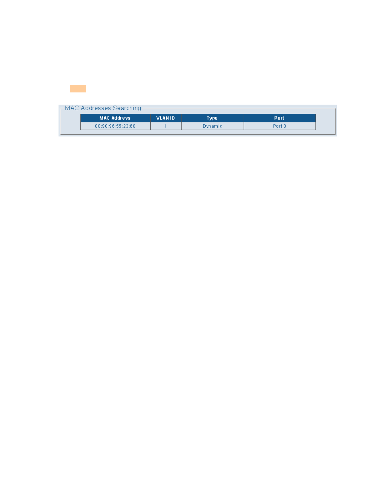
This page display learned mac on LAN1 ~ LAN8. Since we need to search whole lookup table in system, this
page will delay few seconds to display mac entries.
Figure: 4.2.20
Page 29
25
4.3.1.2 Static MAC
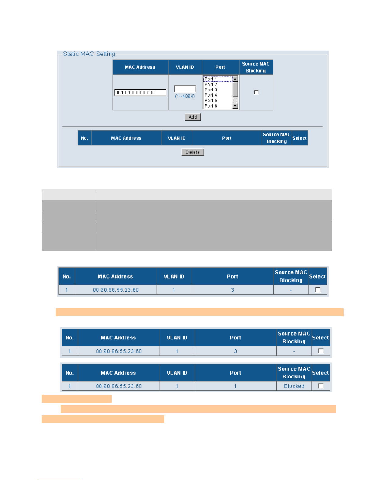
This page shows the static MAC entries, User can add/remove static MAC in this page.
Figure: 4.2.21
Parameter
Description
MAC Address
MAC entries address.
VLAN ID
Default VLAN ID is setting to 1, or Customer Side entry VLAN ID.
Port
Customer Side entry Physical Port.
Source MAC
Blocking
When enable Source MAC Blocking function, this MAC entry rule will be drop
directory.
Note1:
a.) above sample rules mean MAC 00:90:96:55:23:60 entry only Accept from Port 3 and
VID was 1. [white list]
Note2: a.) above sample rules mean MAC 00:90:96:55:23:60 entry will be Dropped even
from Port 3 and VID was 1. [black list]
Page 30
26
4.3.2 Storm Control
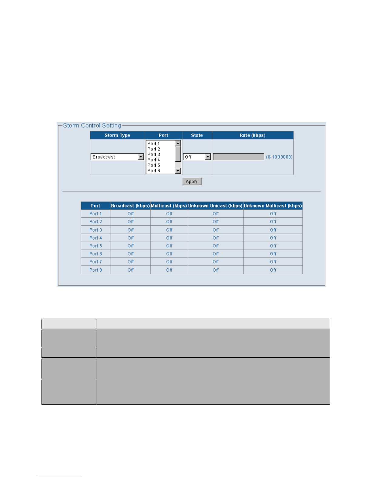
Broadcast storms may occur when a device on your network is malfunctioning, or if application programs are
not well designed or properly configured. If there is too much broadcast traffic on your network, performance
can be severely degraded or everything can come to complete halt.
User can protect your network from broadcast storms by setting a threshold for broadcast traffic for each port.
Any broadcast packets exceeding the specified threshold will then be dropped.
Figure: 4.2.22
Parameter
Description
Storm Type
List the type of traffic which can be rate limited, including Broadcast,Multicast,
Unknown Unicast and Unknow Multicast frames.
Port
Port1, Port2, Port3, Port4, Port5, Port6, Port7, Port8
State
OFF:disable storm control
ON: enable storm control
Rate (kbps)
Rate: number of frame per second. The same threshold is key-in by user from
8-1000000kbps) to the per port setting.When the threshold is exceeded, packets are
dropped, irrespective of the flow-control settings.
Page 31
27
4.4 Monitoring
4.4.1 Port Statistics
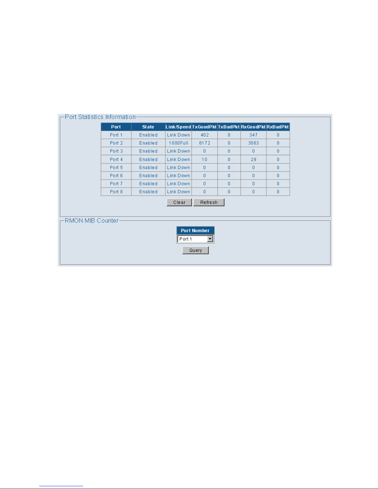
You can display statistics on network traffic from the ports. These statistics can be used to identify potential
problems with the switch (such as a faulty port or unusually heavy loading). All values displayed have been
accumulated since the last system reboot, but can be reset to zero by clicking the Clear button. The current
statistics are not displayed until you click the Refresh button.
Figure: 4.2.23
Page 32
28
4.4.2 Cable Diagnostic
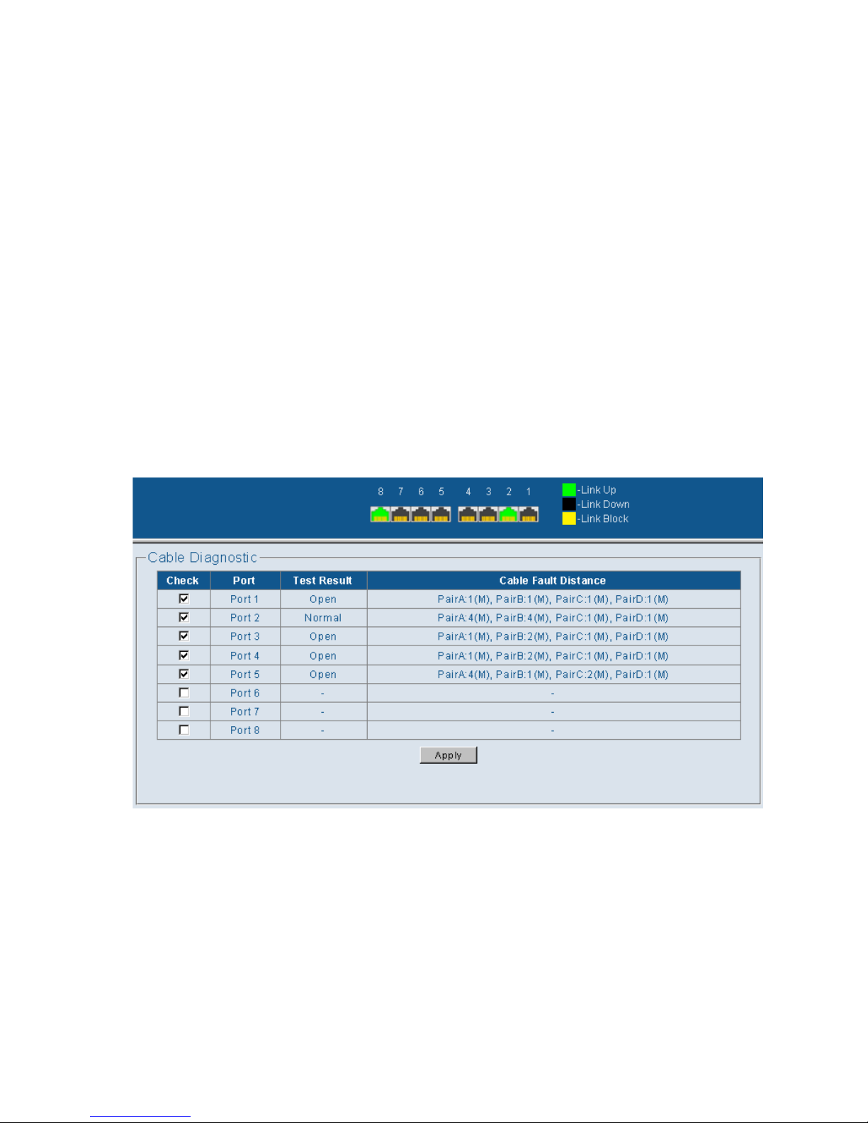
You can perform cable diagnostics for want to “check” ports or selected ports to diagnose any cable
faults (Short, Open etc..) and feedback a distance to the fault.
Field Attributes
• Check – It can be performed on a per-port basis. Select the port that you want to do the cable
diagnostics.
• Apply – running which Physical Port want to check it.
• Testing Result
Open , no cable connect to port
Normal , RJ45 Cable testing result is OK,
Mismatch , RJ45 Cable pair x length not match, please replace this cable.
• Cable Fault Distance – Show the cable length, operating conditions and isolate variety of common
faults that can occur on the CAT5 twisted pair cabling.
Figure: 4.2.23
Page 33
29
4.5 Tools
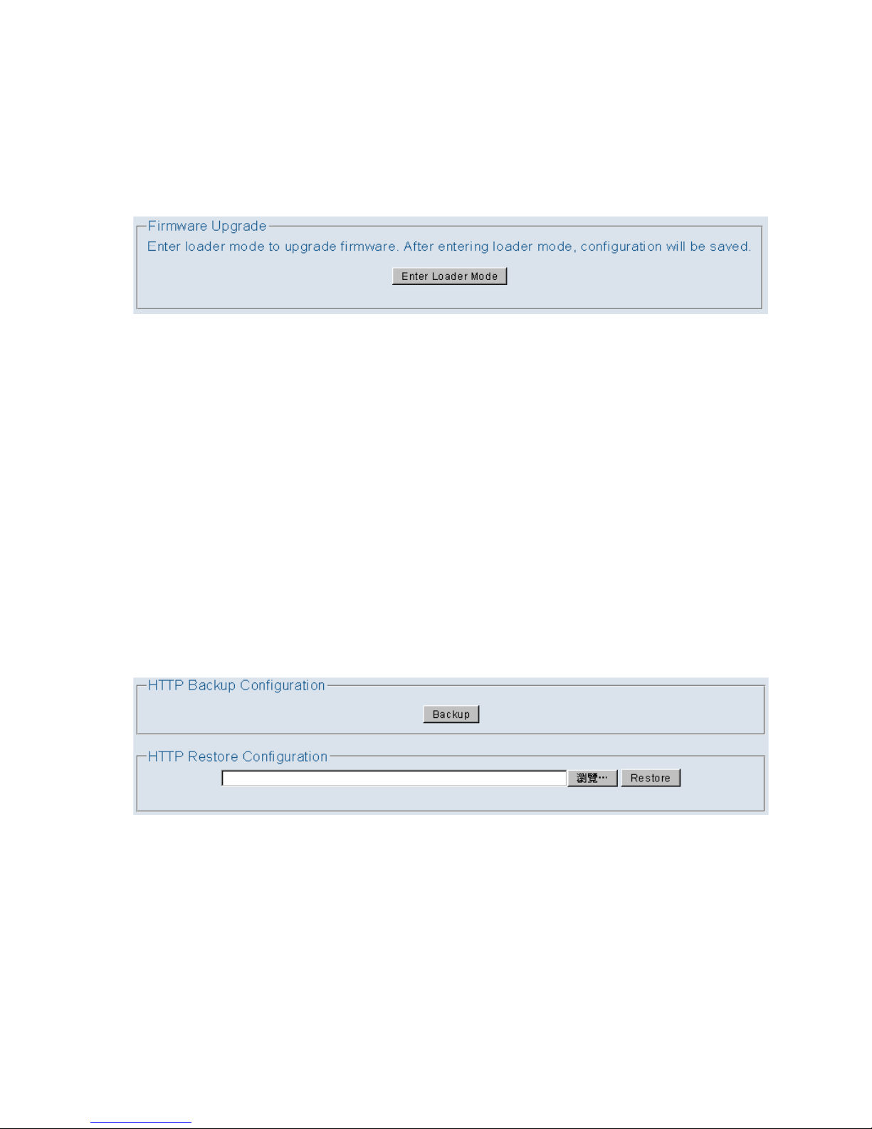
4.5.1 Firmware Upgrade
Enter loader mode to upgrade firmware. After entering loader mode, You can through file upload or tftp to
upgrade the System Firmware.
Figure: 4.2.26
4.5.2 Configuration Backup
The EMS5-8MA-SWITCH enables the user to get a back-up of the configuration file. This will help the user to
install many same series switches with the same configurations.
Backup settings:
Click the “Backup” button and a download window for “switch_cfg.bin” will appear. Save the file in a safe
location for later retrieval.
Restore settings:
Click “Browse” button to select the downloaded/backed-up configuration file, and then press the “Restore”
button. The Switch will restart and apply the settings as in the configuration file.
Figure: 4.2.25
Page 34
30
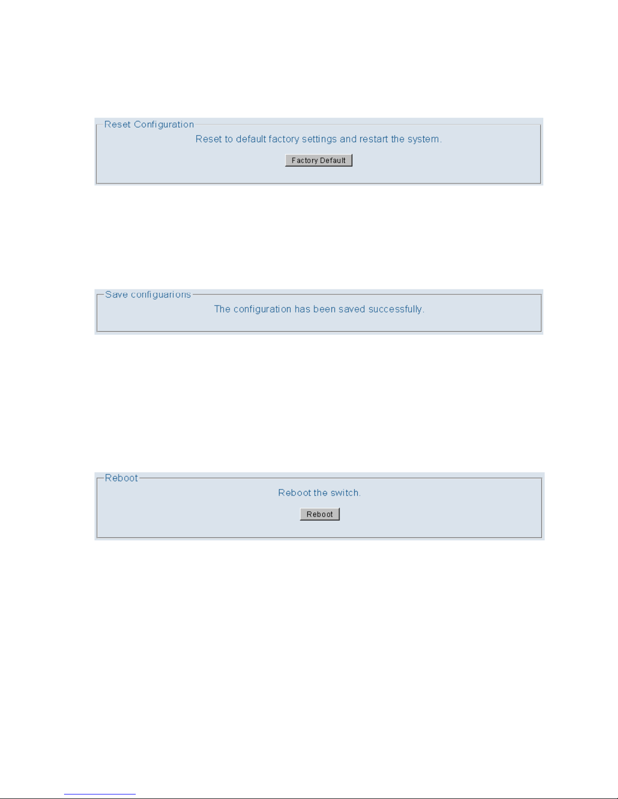
4.5.3 Reset
Into Reset and Clicking on the “Factory Default” button will set the switch back to factory
defaults. All saved configurations will be lost.
Figure: 4.2.26
4.5.4 Save
Click “Save” button to save system configuration.
Figure: 4.2.27
4.5.5 Reboot
Click 'Reboot' buttons to restart the system without turning OFF the power.
Figure: 4.2.28
Page 35
31
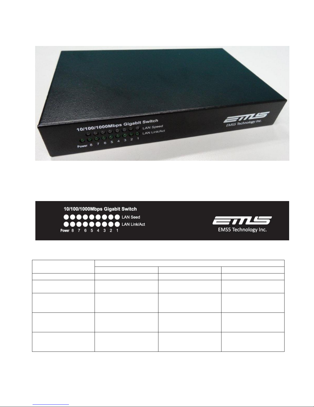
HARDWARE INSTALLATION
Figure: 4.2.29
LED Indicators on the Front Panel
Figure: 4.2.30
LED
Status
Glowing
Dimming
Flashing
POWER
DC 12 power feeding in
Not powered
N/A
LAN1~8 Link/Act
LAN Link
Disconnected or Link
failed
Received or Transmit
LAN Speed
“Orange”
Ethernet operates in
1000Mbps.
Disconnected or Link
failed
N/A
LAN Speed
“Green”
Ethernet operates in
100Mbps.
Disconnected or Link
failed
N/A
LAN Speed
“OFF”
Ethernet operates in
10Mbps.
Disconnected or Link
failed
N/A
Page 36
32
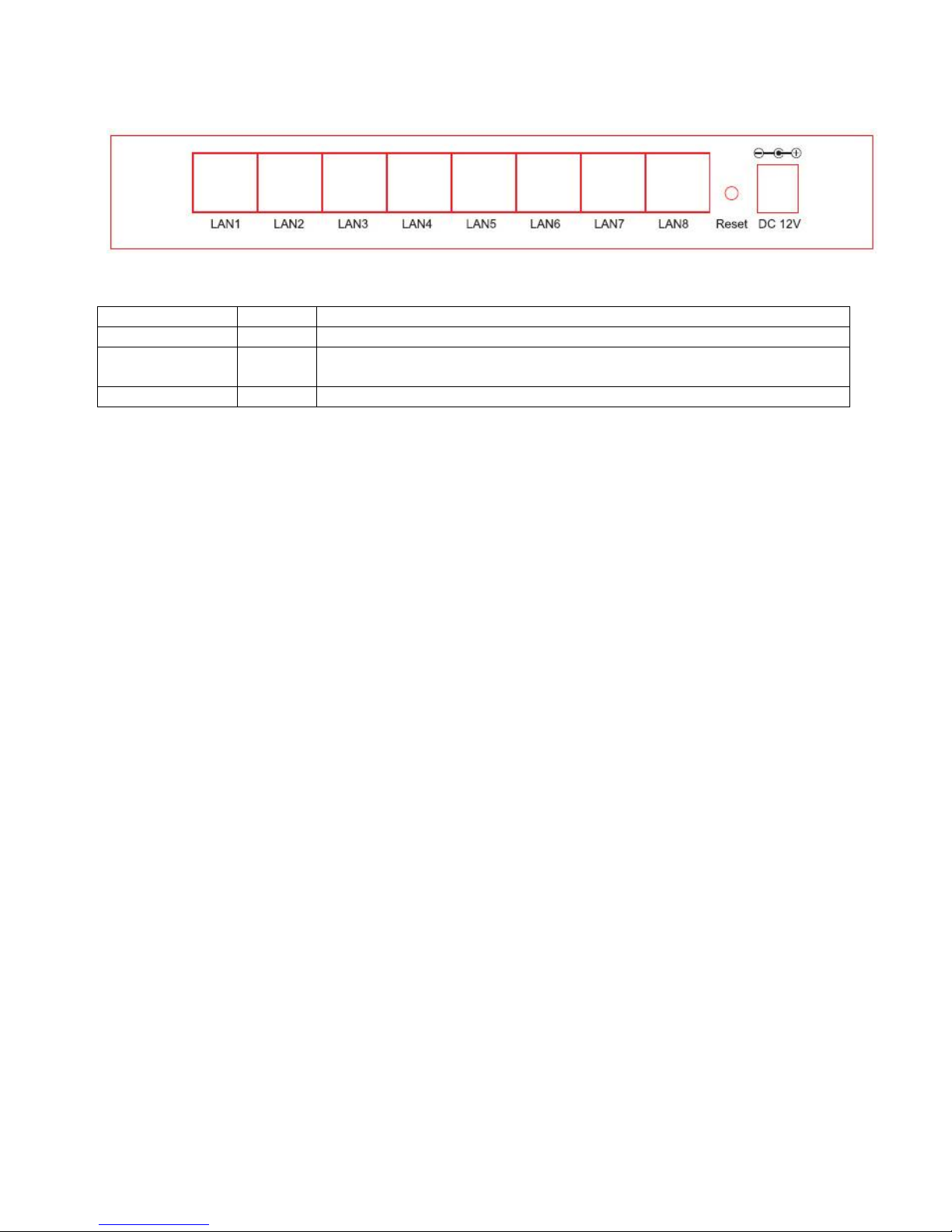
Ports on the Real Panel
Figure: 4.2.31
Port Name
Type
Functions
DC IN
DC 12V
Connects to the power adapter plug.
Reset
Reset
Button
Press Reset button 3~5 sec to Factory Default setting.
LAN1~8
RJ45
Connects to Ethernet port to PC or STB or IP Camera for Internet Access.
Page 37
33
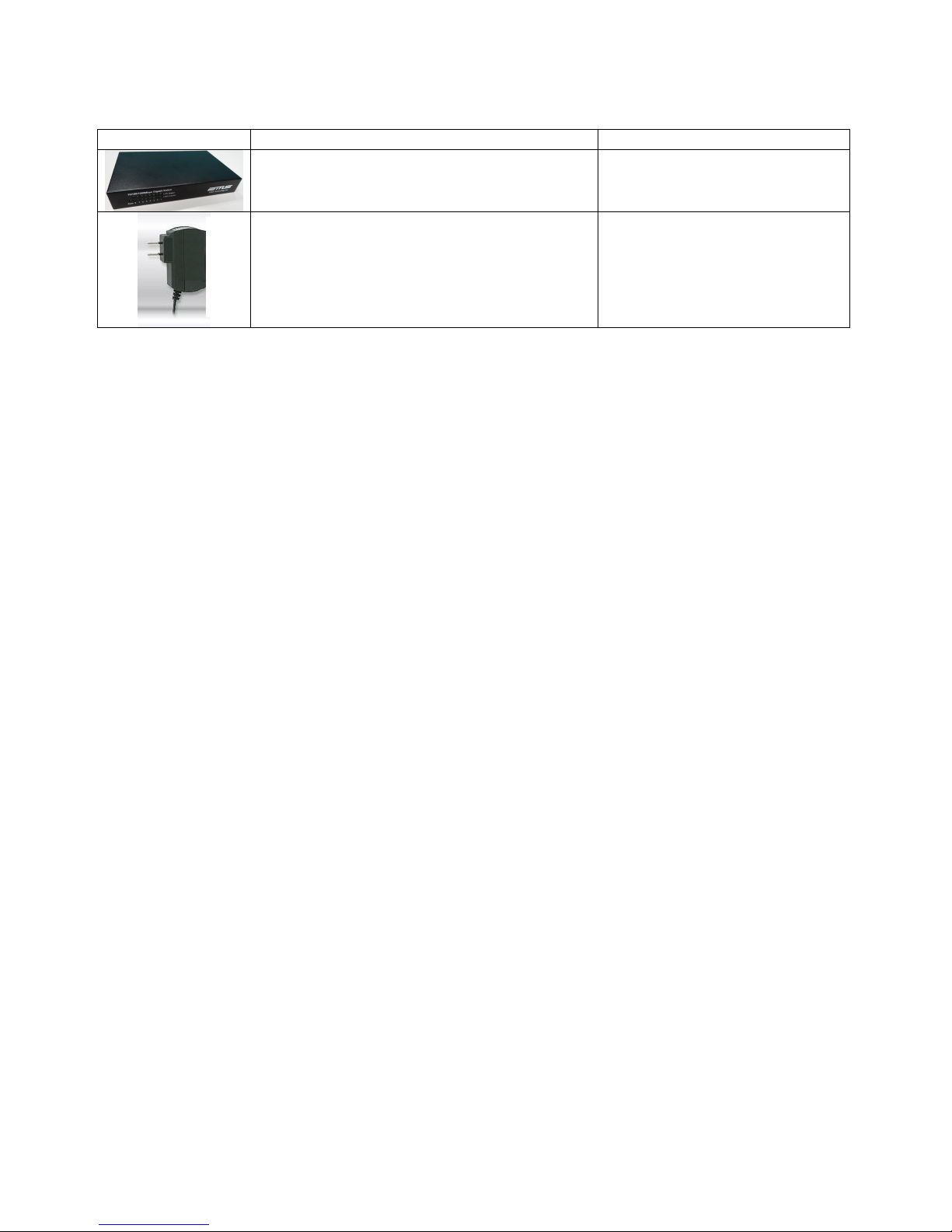
Essential Hardware’s
Items Included
Description
Purpose
EMS5-8MA-SWITCH, Managed, 8 port
GIGA UTP
Main Unit
DC 12V Power Adapter
Connects from Power Port of the
main unit into a wall outlet
Page 38
34
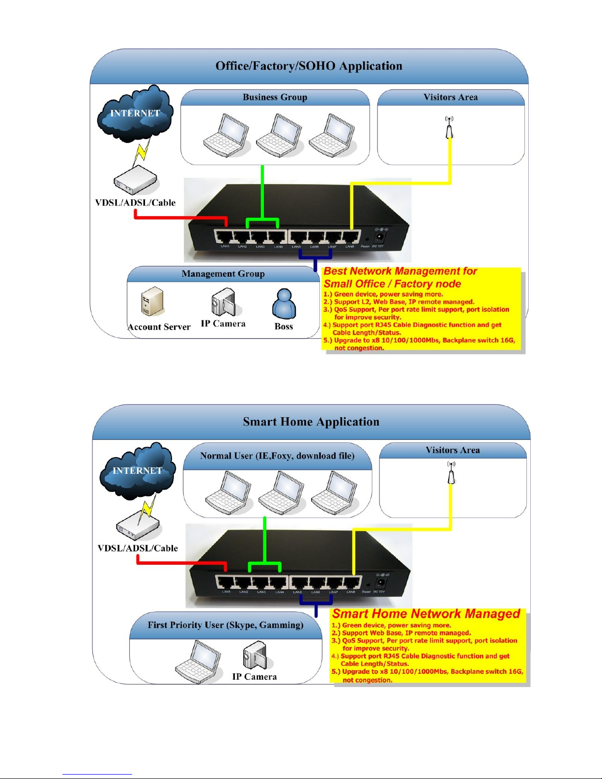
Hardware Connections
Figure: 4.2.32
Page 39
35
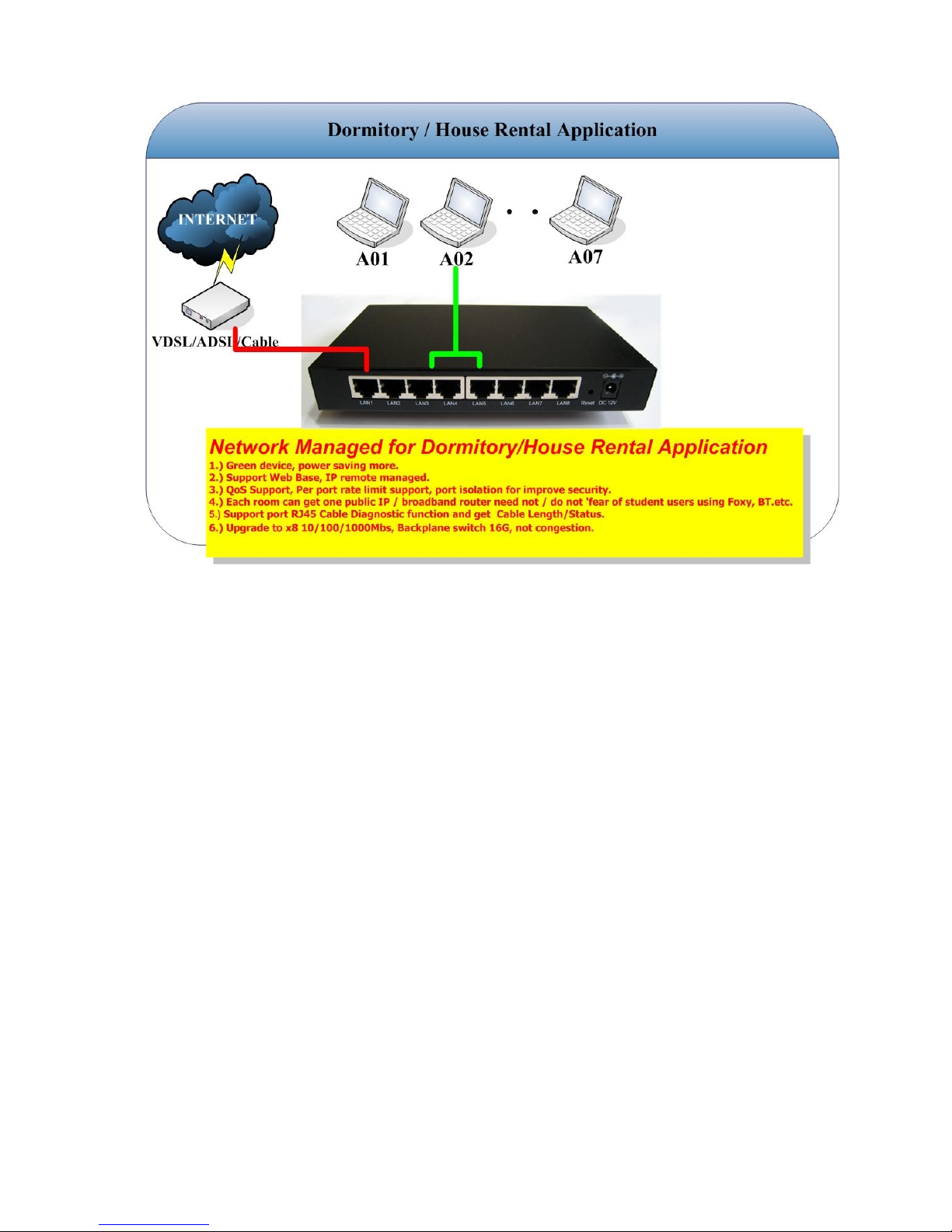
Figure: 4.2.33
Figure: 4.2.34
The figure about shows how to connect an Managed Switch to a Internet network. Follow the same
steps to connect and Ethernet device such as HUB or AP, to a ISP network.
Now you should have connected the Ethernet port and the Power port to the appropriate devices or
lines. LED will be as:
POWER ON
LAN1~8 Link/Act ON
For more information on LEDs, see section “LED Indicators on the Front Panel”
Page 40

36
TROUBLESHOOTING
The Managed Switch had been designed to be a reliable and easy to use connection device. Please
refer to the list below to aid in troubleshooting.
The Power (green) LED is off
Make sure the power adapter is properly plugged into a live electrical outlet.
The LAN Ethernet Link/Act LED is off.
The Ethernet or EMS5-8MA-SWITCH device to which you are connected should be
powered on and properly configured.
Page 41

37
Specifications
LAN Interface Specification
Eight RJ-45 female connector for straight or cross-over connection.
Supports 10/100/1000Base-TX, n-way (Auto-Negotiation)
Supports Full, Half duplex, 10/100/1000 speed Auto mode selections(1000M only support Full duplex mode).
Transmission Packet Rate for 10/100Base-TX: 14880/148800 per second ; 1000Base-T: 1488000 per second
Copper TP cable 4 pair Cat. 5e or 6 UTP
General Specification
Operate in store and forward mode
Support IEEE802.3 10BASE-TX
Support IEEE802.3u 100BASE-TX
Support IEEE802.3ab 1000BASE-T
Support 8K MAC address
Support Auto MDI / MDIX
Support 9K Jumbo Frame
Support TP Port Auto-negotiation(10/100/1000 Base and Full/ Half mode)
Temperature: 0 - 50
℃
(Operating); 0 - 70℃ (Storage).
Humidity: 20-80% non-condensing (Operating); 10-90% (Storage).
Power: DC Jack Switching adapter (12V, 1A) Input; Power consumption: < 6W
Dimensions: 178mm(W) x 110mm(D) x 28mm (H).
Weight: 485g
Compliance: FCC part15 Class B, CE Mark
MTBF: 65,000 h (25
℃
)
Layer II Managed Switch feature Description:
Support Web SNMP managed feature
Support 802.1Q/QoS priority/ port setting
Support Q in Q double VLAN tagging
Support IGMP v1/v2 snooping
Support Port Trunk setting
Support LAN Loop Prevention
Support Port Mirroring
Support port rate limiting from 8K to 1Gbps (step 8K base for Ingress/Egress per port)
Support 9216 Jumbo Frame
Support Green Ethernet
Page 42

38
Support 802.3az EEE function
Support Port Statistics Monitor
Support Port Cable Diagnostic
Support Firmware Upgrade and conf iguration backup
Support Managed VLAN tagging (option)
Support Auto Provision (option)
Diagnostic LEDs:
Power status LED x1
LAN Speed Dual color LED x 8
LAN Link/Act LED x 8
5. Contact Information
Contact Information:
Email: [email protected]
 Loading...