

Page 1
ZITON RADIO LOOP MODULE
PROGRAMMING
MANUAL
Page 2

Table of Contents
Section Page No
1.0 INTRODUCTION .................................................................................... 3
1.1 System Design...................................................................................... 3
1.2 Handling Precautions ............................................................................. 3
1.3 Packaging: ........................................................................................... 3
2.0 MENU STRUCTURE ................................................................................ 4
2.1 Menu Structure Layout........................................................................... 4
3.0 MENU EXPLANATION ............................................................................. 5
3.1 Device Status ....................................................................................... 5
3.2 Add New device .................................................................................. 12
3.3 Remove device ................................................................................... 13
3.4 Interface Status ................................................................................. 13
3.5 Radio Channels .................................................................................. 14
4.0 FRONT DISPLAY OF RADIO LOOP MODULE ............................................ 14
5.0 ACCESSING THE RADIO LOOP MODULES MENUS ................................... 14
5.1 Viewing the Device Status ................................................................... 15
5.2 Output Test ........................................................................................ 19
5.3 Adding New Devices to the System....................................................... 20
5.4 Removing Device from the System ....................................................... 21
5.5 Viewing the Radio Loop Module Status .................................................. 22
5.6 Radio Channels .................................................................................. 23
Tel: +44 (0) 1227 369570 Fax: +44 (0) 1227 369679 Email: enquiries@emsgroup.co.uk Website: www.emsgroup.co.uk
Ziton Radio Loop Module Programming Manual (Issue 7d) TSD022
EMS Group Head Office, Technology House, Sea Street, Herne Bay, Kent CT6 8JZ, England
2
Page 3

1.0 INTRODUCTION
This manual provides a programming guide for the Ziton Radio Loop Module.
The Ziton Radio Loop Module comprises of a radio transceiver capable of receiving 31 radio
devices. An LCD display is provided along with function buttons to allow programming and
diagnostics to be carried out for associated devices.
The Ziton Radio Loop Module is capable of connection to a ZP Protocol Fire Alarm Control Panels
Loop via its Loop in and out connection terminals. The Radio Loop Module is addressed on the
loop via its onboard 8 way DIP switch. A total of 2 Radio Loop Modules can be fitted onto a Fire
Alarm Control Panels Loop.
Compatible products for use with the Ziton Radio Loop Module are as follows;
Part Number – ZR485-3 Radio manual call point
Part Number – ZR432-2 Radio multisensor detector
Part Number – ZR455-3R Red radio sounder
Part Number – ZR455-3W White radio sounder
Part Number – ZR455V-3RC Red radio sounder with clear beacon
Part Number – ZR455V-3RR Red radio sounder and red beacon
Part Number – ZR455V-3RA Red radio sounder with amber beacon
Part Number – ZR451-3 Single input output unit
1.1 System Design
All installation work should be carried out in accordance with the survey and system design.
It is recommended that the Ziton Radio Loop Module and peripheral devices are located in
accordance with the radio survey and system design. This should be established before
installation work commences.
1.2 Handling Precautions
General; Care should be taken when handling Ziton Radio Loop Module. Avoid dropping any of the
parts onto hard surfaces, as damage may occur to the case and internal circuitry.
ESD Precautions; Ziton Radio Loop Module includes components that are susceptible to damage
from Electro-Static Discharge (ESD). Permanent damage may be caused to these components
through routine handling if precautions are not observed. To reduce the risk of damage from ESD,
the following precautions should be observed.
Minimise the handling of PCB’s which contain static sensitive devices. Where handling is
unavoidable, always ensure that you have taken adequate earthing precautions. An earthed wrist
strap is recommended.
When storing or transporting a “loose” PCB, always use a container, which has been designed and
manufactured with ESD protective properties.
Avoid placing static sensitive devices on plastic surfaces, which may increase the risk of a static
discharge.
1.3 Packaging:
All products should be kept in their packaging until they are due to be installed, to minimise the
risk of damage. Retain all packaging until the installation activities have been completed. Should
any product be found to be surplus to requirements, or require returning, the original packaging
should be used.
Tel: +44 (0) 1227 369570 Fax: +44 (0) 1227 369679 Email: enquiries@emsgroup.co.uk Website: www.emsgroup.co.uk
Ziton Radio Loop Module Programming Manual (Issue 7d) TSD022
EMS Group Head Office, Technology House, Sea Street, Herne Bay, Kent CT6 8JZ, England
3
Page 4
2.0 MENU STRUCTURE
The menu structure is shown below and is entered by pressing the Rotary Control button.
Further menu options are entered by also pressing the Rotary Control button. To exit the menus
the back button can be pressed or the menus will automatically exit one step at a time at 30
second time intervals.
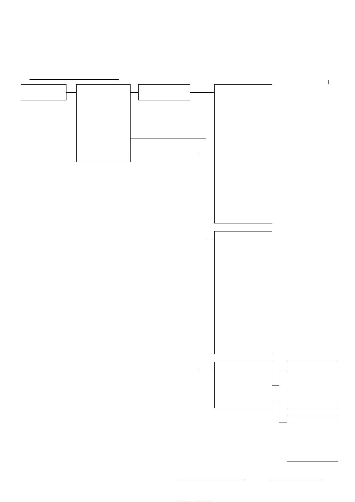
2.1 Menu Structure Layout
Front Screen
Device Status
Add New Device
Remove Device
Interface Status
Radio Channel
Device Address
Fault Status
Alarm Status*
Battery Level
Signal Level
Manual Update
Ident
Software Version
Loop Address
Output Test**
Fault Status
Background Level
Ident
Software Version
Node Number **
Audio Detect **
Batt Smooth **
Serial Data **
Currently Used
Auto Select ***
Manual Select ***
Scan Time
First Channel
Second Channel
* Alarm Status shown as I/O Status for Input/Output Device types.
** Highlighted menu options are only available when switch 8 is
‘ON’.
*** Menu Options only available when Radio Loop Module does not
have any devices allocated to it.
Scan Time
First Channel
Second Channel
Tel: +44 (0) 1227 369570 Fax: +44 (0) 1227 369679 Email: enquiries@emsgroup.co.uk Website: www.emsgroup.co.uk
Ziton Radio Loop Module Programming Manual (Issue 7d) TSD022
EMS Group Head Office, Technology House, Sea Street, Herne Bay, Kent CT6 8JZ, England
4
Page 5

3.0 MENU EXPLANATION
3.1 Device Status
This function allows the current status of the allocated devices on the Radio Loop Module to be
viewed (Maximum of 31 devices). The devices are shown in the menu indicating their loop
address number, its logged on status and the device type. Further information on the device can
be obtained by pressing the Rotary Control button. This enables the following details to be
viewed:- Fault status, Alarm Status, Battery Level, Signal Level, unique 5 digit ident number,
software version and also allows a manual signal level update to take place.
A typical display is shown below;
Addr 067 L Multi
The descriptions for the shown display are as follows;
Addr 067 – In this example this indicates the devices loop address number which has been
selected. Available options are between 1 and 127.
L – In this example this field indicates the devices logged on or fault status.
Available options are;
L= Logged On and in a normal condition.
! = Logged On with fault(s) present.
= Logged On with a fire alarm present.
= Logged On with a pre alarm present.
Multi – This field indicates the device type. Available options are:
Radio = Ziton Radio Loop Module
Multi = Multisensor Detector
Optic = Optical Detector
Heat = Heat Detector
HTemp = Heat Detector
MCP = Manual Callpoint
Sound = Sounder Device
I/O = Input/Output Device
??? = Unknown Device
Further Device Status Information on the displayed device is available by pressing the Rotary
Control button. This allows the following menus to be viewed;
Fault Status – this menu when entered, shows detailed information on the fault status of the
device.
Note; If multiple faults are applicable to a device the rotary control can be turned to view the
total fault listing and a down arrow will be present to indicate that there is more than one fault
present
The available fault descriptions are described below;
Tel: +44 (0) 1227 369570 Fax: +44 (0) 1227 369679 Email: enquiries@emsgroup.co.uk Website: www.emsgroup.co.uk
Ziton Radio Loop Module Programming Manual (Issue 7d) TSD022
EMS Group Head Office, Technology House, Sea Street, Herne Bay, Kent CT6 8JZ, England
5
Page 6

No Fault Present – this description indicates that the device is not in any fault condition and is
operating correctly.
The analogue value seen on the Fire Alarm Control Panel in their normal status will vary
depended upon the signal strength readings. The range of values is shown below:
Analogue
Value
Signal
Strength
GOOD
(Slot 5)
Analogue
Value
Signal
Strength
MEDIUM
(Slot 5)
Analogue
Value
Signal
Strength
LOW
(Slot 5)
Analogue
Value
Signal
Strength
CAUTION
(Slot 5)
Detector 090 085 080 075
Manual Call Point 090 085 080 075
Sounder 090 085 080 075
Input/Output 090 085 080 075
In Tamper – this indicates that the devices tamper switch is not currently making contact
against the ceiling or wall mounted base plate.
The analogue value seen on the Fire Alarm Control Panel for devices in this state is;
Analogue Value
(Slot 5) (Slot 6)
Detector N/A 181
Manual Call Point N/A 181
Sounder N/A 181
Input/Output N/A 181
Head Missing – this indicates that the detectors head is not currently fitted on the detector
base.
The analogue value seen on the Fire Alarm Control Panel for devices in this state is;
Analogue Value
(Slot 3) (Slot 6)
Detector 244 118
Manual Call Point N/A N/A
Sounder N/A N/A
Input/Output N/A N/A
Sounder Missing – this indicates that the sounder, strobe only or sounder/strobe head is not
currently fitted on the sounder base.
The analogue value seen on the Fire Alarm Control Panel for devices in this state is;
Analogue Value
(Slot 3) (Slot 6)
Detector N/A N/A
Manual Call Point N/A N/A
Sounder 244 118
Input/Output N/A N/A
Tel: +44 (0) 1227 369570 Fax: +44 (0) 1227 369679 Email: enquiries@emsgroup.co.uk Website: www.emsgroup.co.uk
Ziton Radio Loop Module Programming Manual (Issue 7d) TSD022
EMS Group Head Office, Technology House, Sea Street, Herne Bay, Kent CT6 8JZ, England
6
Page 7

Signal Fault – this indicates that there has currently not been any communication between
the device and the Radio Loop Module for 300 seconds. This is indicated as an analogue value
of 020 on the fire alarm control panel.
This will be shown on the Fire Alarm Control Panel as if the device had been removed from the
system as it does not respond to polls on the loop i.e Disconnect fault.
The analogue value seen on the Fire Alarm Control Panel for devices in this state is;
Analogue Value
Slot 5 Slot 6
Detector 020 N/A
Manual Call Point 020 N/A
Sounder 020 N/A
Input/Output 020 N/A
Battery Fault – this shows that the device has either a low battery and has a minimum
operational life of 7- 30 days or has a battery missing.
The analogue value seen on the Fire Alarm Control Panel for devices with low batteries is;
Analogue Value
Slot 5 Slot 6
Detector N/A 213
Manual Call Point N/A 213
Sounder N/A 213
Input/Output N/A 213
The analogue value seen on the Fire Alarm Control Panel for devices with a battery missing is;
Analogue Value
Slot 5 Slot 6
Detector N/A 020
Manual Call Point N/A 020
Sounder N/A 020
Input/Output N/A 020
This will be shown as Idle High on the Fire Alarm Control Panel as if the device has a fault.
No Sndr Audio – this indicates that a sounder device has given no audio output or a low audio
output when sounding. This is selectable via a DIP switch on the sounder head and must be
disabled when using strobe only devices.
The analogue value seen on the Fire Alarm Control Panel for devices in this state is;
Analogue Value
Slot 3 Slot 6
Detector N/A N/A
Manual Call Point N/A N/A
Sounder 244 152
Input/Output N/A N/A
Tel: +44 (0) 1227 369570 Fax: +44 (0) 1227 369679 Email: enquiries@emsgroup.co.uk Website: www.emsgroup.co.uk
Ziton Radio Loop Module Programming Manual (Issue 7d) TSD022
EMS Group Head Office, Technology House, Sea Street, Herne Bay, Kent CT6 8JZ, England
7
Page 8

Head Fault – this indicates that a detectors head has a fault i.e no communication between
the head and the radio base.
The analogue value seen on the Fire Alarm Control Panel for devices in this state is;
Analogue Value
Slot 3 Slot 6
Detector 244 152
Manual Call Point N/A N/A
Sounder N/A N/A
Input/Output N/A N/A
Short Circuit – this indicates that an input has a short circuit wiring fault.
The analogue value seen on the Fire Alarm Control Panel for devices in this state is;
Analogue Value
Slot 5 Slot 6
Detector N/A N/A
Manual Call Point N/A N/A
Sounder N/A N/A
Input/Output N/A 118
Open Circuit – this indicates that an input has a short circuit wiring fault.
The analogue value seen on the Fire Alarm Control Panel for devices in this state is;
Analogue Value
Slot 5 Slot 6
Detector N/A N/A
Manual Call Point N/A N/A
Sounder N/A N/A
Input/Output N/A 118
Alarm Status – this menu when entered shows information on the current alarm status of the
device. The available alarm descriptions are described below;
No Alarm Present – this indicates the device is currently not in an alarm or pre-alarm
condition.
In Fire – this indicates the device is currently in a fire alarm condition.
The analogue value seen on the Fire Alarm Control Panel for devices in this state is;
Analogue Value
Slot 5 Slot 6
Detector 181 N/A
Manual Call Point 181 N/A
Sounder N/A N/A
Input/Output 213 N/A
Tel: +44 (0) 1227 369570 Fax: +44 (0) 1227 369679 Email: enquiries@emsgroup.co.uk Website: www.emsgroup.co.uk
Ziton Radio Loop Module Programming Manual (Issue 7d) TSD022
EMS Group Head Office, Technology House, Sea Street, Herne Bay, Kent CT6 8JZ, England
8
Page 9

In Pre-Alarm – this indicates the device is currently in a Pre-alarm condition.
The analogue value seen on the Fire Alarm Control Panel for devices in this state is;
Analogue Value
Slot 5 Slot 6
Detector 152 N/A
Manual Call Point N/A N/A
Sounder N/A N/A
Input/Output N/A N/A
I/O Status – this menu replaces the Alarm Status menu for Input/Output devices. When
entered this shows information on the current status of the two inputs for the device. The
available status descriptions are described below;
IN1: 0 – this indicates that input 1 is in the open (normal) state.
IN1: 1 – this indicates that input 1 is in the closed (activated) state.
IN2: 0 – this indicates that input 2 is in the open (normal) state.
IN2: 1 – this indicates that input 2 is in the closed (activated) state.
The analogue value seen on the Fire Alarm Control Panel for devices with inputs in the normal
state is;
Analogue Value
Slot 5 Slot 6
Detector N/A N/A
Manual Call Point N/A N/A
Sounder N/A N/A
Input/Output 090 244
The analogue value seen on the Fire Alarm Control Panel for devices with inputs in the closed
state is;
Analogue Value
Slot 5 Slot 6
Detector N/A N/A
Manual Call Point N/A N/A
Sounder N/A N/A
Input/Output 213 N/A
Battery Level – this menu when entered shows information on the battery pack status for a
device. A device has 2 packs, the status of each of these can be viewed from this menu. The
status of the pack is updated whenever there is a status change or automatically updated every 6
hours. The available battery descriptions are described below;
Pack 1 OK – this indicates a good battery voltage is present in Pack 1. This is represented by
displaying a full battery icon.
Pack 1 Warning – this indicates the battery voltage is low in Pack 1 and is a 30 day warning
indication. The batteries must be changed on the device within 30 days for continued reliable
operation. This is represented by displaying a half full battery icon.
Pack 1 Low – this indicates the battery voltage is low in Pack 1 and is a 7 day warning
indication. The batteries must be changed on the device within 7 days for continued reliable
operation. This is represented by displaying an empty battery icon.
Tel: +44 (0) 1227 369570 Fax: +44 (0) 1227 369679 Email: enquiries@emsgroup.co.uk Website: www.emsgroup.co.uk
Ziton Radio Loop Module Programming Manual (Issue 7d) TSD022
EMS Group Head Office, Technology House, Sea Street, Herne Bay, Kent CT6 8JZ, England
9
Page 10

Pack 1 Missing – this indicates a battery from Pack 1 is missing. The battery must be inserted
on the device for continued reliable operation. This is represented by displaying an X symbol.
Pack 2 OK – this indicates a good battery voltage is present in Pack 2. This is represented by
displaying a full battery icon.
Pack 2 Warning – this indicates the battery voltage is low in Pack 2 and is a 30 day warning
indication. The batteries must be changed on the device within 30 days for continued reliable
operation. This is represented by displaying a half full battery icon.
Pack 2 Low – this indicates the battery voltage is low in Pack 2 and is a 7 day warning
indication. The batteries must be changed on the device within 7 days for continued reliable
operation. This is represented by displaying an empty battery icon.
Pack 2 Missing – this indicates a battery from Pack 2 is missing. The battery must be inserted
on the device for continued reliable operation. This is represented by displaying an X symbol.
Signal Level – this menu when entered shows information on the two signalling channels used
by the Radio Loop Module in both directions, as the devices are bi-directional. The received
signal strength at the Radio Loop Module from the device is shown as an LI Dev level,
therefore indicating the signal that has been sent from the device to the Radio Loop Module. The
LI Dev level is updated on every poll response (123 seconds). The forward signal strength
received at a device from the Radio Loop Module is shown as an LI Dev level, therefore
indicating the signal that has been sent from the Radio Loop Module to the device. The LI Dev
level is updated every 6 hours or when requested manually by selecting the Manual Update
Option from the menu.
Ch 1 LI Dev – this indicates the received signal strength at the Radio Loop Module from the
device on the first frequency channel used by the system. A level from 100 -0 is shown to
indicate the levels, a table of which is shown at the end of this section.
Ch 2 LI Dev – this indicates the received signal strength at the Radio Loop Module from the
device on the second frequency channel used by the system. A level from 100 -0 is shown to
indicate the levels, a table of which is shown at the end of this section.
Ch 1 LI
Dev – this indicates the forward signal strength received at the device from the Radio
Loop Module on the first frequency channel used by the system. A level from 100 -0 is shown to
indicate the levels, a table of which is shown at the end of this section.
Ch 2 LI
Dev – this indicates the forward signal strength received at the device from the Radio
Loop Module on the second frequency channel used by the system. A level from 100 -0 is shown
to indicate the levels, a table of which is shown at the end of this section.
The individual devices have signal levels available for both of their operating channels (Ch1 and
Ch2) and also for both directions (Radio Loop Module to Device (LI Dev) and Device to Radio
Loop Module (LI Dev)) as the devices are bi-directional. The signal levels shown range from
100 - 0 with 100 being the highest signal to 0 where no signal is being seen, as shown below;
100 Shown indicates Good Signal Level
90 Shown indicates Good Signal Level
80 Shown indicates Good Signal Level
70 Shown indicates Good Signal Level
60 Shown indicates Good Signal Level
50 Shown indicates Good Signal Level
40 Shown indicates Medium Signal Level
30 Shown indicates Low Signal Level
20 Shown indicates Caution Signal Level
10 Shown indicates Caution Signal Level
0 Shown indicates No Signal Level Received
Tel: +44 (0) 1227 369570 Fax: +44 (0) 1227 369679 Email: enquiries@emsgroup.co.uk Website: www.emsgroup.co.uk
Ziton Radio Loop Module Programming Manual (Issue 7d) TSD022
EMS Group Head Office, Technology House, Sea Street, Herne Bay, Kent CT6 8JZ, England
10
Page 11

An algorithm incorporating both channels and the channels background is employed to indicate
the analogue values displayed at the associated control panel and therefore determining the
devices signal strength. This is shown in the table below.
Analogue
Value
Displayed at
Radio Device
Type
Device Signal Strength Level
Control Panel
Slot 5 Slot 6
020 N/A All Device Types No Radio Signal received. Device Missing
075 N/A All Device Types Radio Signal strength caution.
080 N/A All Device Types Radio Signal strength low.
085 N/A Detector Radio Signal strength medium.
090 N/A Detector Radio Signal strength good.
The device to Radio Loop Module information is updated every time the device responds to a poll
which is every 123 seconds. The Radio Loop Module to device information is automatically
updated every 6 hours or if a manual update is requested.
The minimum recommend level is 50 points or above on each channel.
Manual Update – This menu when entered will automatically send signals from the Radio Loop
Module to the individual device and ask for its current signal level status to be transmitted back
to the Radio Loop Module. This will then automatically update the Signal level fields for the
device. If a signal level field is still awaiting an update from a channel 0 will be shown in the
field.
Ident – This menu shows the unique 5 digit identification number for the device.
Software Version – This menu shows the software version currently installed in the device.
Node Number – This menu should only be used when two Radio Loop Modules are connected to
one of the Control Panels loops. The first Radio Loop Modules Node Number should be set as 1
whilst the second Radio Loop Modules Node Number should be set as 2.
Loop Address - This menu allows you to view the device’s current loop address. A new device
loop address can be selected by pressing the rotary control, thus choosing an alternative address.
Output Test – This menu allows you to turn device LED’s on.
Tel: +44 (0) 1227 369570 Fax: +44 (0) 1227 369679 Email: enquiries@emsgroup.co.uk Website: www.emsgroup.co.uk
Ziton Radio Loop Module Programming Manual (Issue 7d) TSD022
EMS Group Head Office, Technology House, Sea Street, Herne Bay, Kent CT6 8JZ, England
11
Page 12

3.2 Add New device
Radio Callpoint
Radio Multis
ensor
Radio Sounder
Radio
Input Output Unit
This menu allows the adding of new radio devices to the Radio Loop Module. A maximum of 31
devices are allowed. When this menu is entered the log on button must be pressed on the new
device. A confirmation of the device ident number is requested and when accepted will add the
device to the Radio Loop Module. The log on button can be found on the devices in the following
locations;
Callpoint
Log On
Button
Detector
Log On
Button
Sounder
Log On
Button
Sounder
Log On
Button
Tel: +44 (0) 1227 369570 Fax: +44 (0) 1227 369679 Email: enquiries@emsgroup.co.uk Website: www.emsgroup.co.uk
Ziton Radio Loop Module Programming Manual (Issue 7d) TSD022
EMS Group Head Office, Technology House, Sea Street, Herne Bay, Kent CT6 8JZ, England
12
Page 13

3.3 Remove device
This menu allows removal of devices from the Radio Loop Module. A list of devices on the Radio
Loop Module are shown and the applicable device to be removed can be selected. A confirmation
of the device to be removed is required prior to removal.
3.4 Interface Status
This function allows the current status of the Radio Loop Module to be viewed. Available options
are: - Fault status, Background Level, Unique ident number and Software version. Additional
more detailed options are available by pressing the Navigation button on the required item. This
allows the following menus to be viewed;
Fault Status – this menu when entered shows detailed information on the fault status of the
Radio Loop Module. If multiple faults are outstanding for the Radio Loop Module then by turning
the rotary control they can be individually viewed. The available fault descriptions are described
below;
No Fault Present – this description indicates that the Radio Loop Module is not in any fault and
is operating normally.
The analogue value seen on the Fire Alarm Control Panel for this state is;
Analogue Value
Slot 5 Slot 6
Radio Loop
090 244
Module
Ch1RFI Det – this description indicates that a radio frequency interference signal has been
detected on radio channel 1 that the system is operating on.
Ch2 RFI Det– this description indicates that a radio frequency interference signal has been
detected on radio channel 2 that the system is operating on.
The analogue value seen on the Fire Alarm Control Panel for when both Ch 1 and Ch 2 are in this
state is;
Analogue Value
Slot 5 Slot 6
Ziton Radio Loop
181 118
Module
Background Level – this menu when entered shows the background radio signal level on the
two signalling channels used by the Ziton Radio Loop Module. The available background level
descriptions are described below;
Ch 1 – this indicates the background level at the Radio Loop Module on the first frequency
channel used by the system. A range from 100 – 0 is shown to indicate the levels, a table of
which is shown at the end of this section.
Ch 2 – this indicates the background level at the Radio Loop Module on the second frequency
channel used by the system. A range from 100 – 0 is shown to indicate the levels, a table of
which is shown at the end of this section.
100 shown indicates VERY HIGH
75 shown indicates HIGH
50 shown indicates MEDIUM
25 shown indicates LOW
0 shown indicates GOOD.
Tel: +44 (0) 1227 369570 Fax: +44 (0) 1227 369679 Email: enquiries@emsgroup.co.uk Website: www.emsgroup.co.uk
Ziton Radio Loop Module Programming Manual (Issue 7d) TSD022
EMS Group Head Office, Technology House, Sea Street, Herne Bay, Kent CT6 8JZ, England
13
Page 14

Ident – this menu shows the unique identification number for the device.
Software Version – This menu details the software version of the Radio Loop Module.
Legacy Mode – To ensure correct operation of devices reporting to the Control Panel, Legacy
Mode must be correctly selected.
Legacy Mode ‘ON’ is to be selected when the Ziton Radio Loop Module is connected to a ZP3
Panel.
Legacy Mode ‘OFF’ is to be selected when the Ziton Radio Loop Module is connected to a ZP2
(2010) Panel.
3.5 Radio Channels
This menu allows the two frequency channels currently used by the Radio Loop Module to be
viewed and also allows the channels used to be selected either manually or automatically. 32
channels are available for use on the system and these are as follows;
Ch1: 868.048 MHz Ch9: 868.248 MHz Ch17: 868.749 MHz Ch25: 868.950 MHz
Ch2: 868.073 MHz Ch10 868.273 MHz Ch18: 868.774 MHz Ch26: 868.975 MHz
Ch3: 868.098 MHz Ch11: 868.298 MHz Ch19: 868.800 MHz Ch27: 869.000 MHz
Ch4: 868.123 MHz Ch12: 868.323 MHz Ch20: 868.825 MHz Ch28: 869.025 MHz
Ch5: 868.148 MHz Ch13: 868.349 MHz Ch21: 868.850 MHz Ch29: 869.050 MHz
Ch6: 868.173 MHz Ch14: 868.374 MHz Ch22: 868.875 MHz Ch30: 869.075 MHz
Ch7: 868.198 MHz Ch15: 868.399 MHz Ch23: 868.900 MHz Ch31: 869.100 MHz
Ch8: 868.223 MHz Ch16: 868.424 MHz Ch24: 868.925 MHz Ch32: 869.125 MHz
4.0 FRONT DISPLAY OF RADIO LOOP MODULE
• The front display of the Ziton Radio Loop Module will show the number of devices that are
allocated it, along with the total number of current alarm and fault conditions. The DEV field
shows the total number of devices allocated between 00-31. The AL field shows the amount of
devices currently with outstanding Alarms and Pre-alarms ranging between 00-31. The FT
field shows the amount of devices currently with outstanding Faults ranging between 00-31.
An example display will show;
5.0 ACCESSING THE RADIO LOOP MODULES MENUS
• To access the Users menu’s from the front display screen , follow the steps listed below:
• Press the rotary control. The display will change to show;
• The Menu structure can be viewed by scrolling through the menu by turning the rotary control.
Entry into the required menu is achieved by locating the required menu on the display and
pressing the rotary control. Exiting from a menu option is achieved automatically after 30
seconds or by pressing the Radio Loop Modules back button.
DEV01 AL00 FT00
DEV01 AL00 FT00
Device Status
Tel: +44 (0) 1227 369570 Fax: +44 (0) 1227 369679 Email: enquiries@emsgroup.co.uk Website: www.emsgroup.co.uk
Ziton Radio Loop Module Programming Manual (Issue 7d) TSD022
EMS Group Head Office, Technology House, Sea Street, Herne Bay, Kent CT6 8JZ, England
14
Page 15

5.1 Viewing the Device Status
• Enter the menu structure by pressing the rotary control.
• Turn the Rotary control until the display shows;
Device Status
• Press the rotary control and the display will change to show the devices allocated onto the
Ziton Radio Loop Module and their current status. The list can be viewed by turning the rotary
control. The information is shown in the following format;
Addr 067 L Multi
Addr 067 – In this example this indicates the devices loop address number (067). Available
options are between 1 and 127.
L – In this example this field indicates the devices logged on or fault status. Available options
are;
L= Logged On and in a normal condition.
! = Logged On with fault(s) present.
= Logged On with a fire alarm present.
= Logged On with a pre alarm present.
Multi – This field indicates the device type. Available options are:
Radio = Radio Loop Module Module
Multi = Multisensor Detector
Optic = Optical Detector
Heat = Heat Detector
HTemp = Heat Detector
MCP = Manual Callpoint
Sound = Sounder Device
I/O = Input/Output Device
??? = Unknown Device
• For more detailed information on the device displayed press the Rotary control. This
information will always be available regardless of the status identifier of the device. The list of
available information is shown in the following format;
Fault Status
Alarm Status *
Battery Level
Signal Level
Manual Update
Ident xxxxx
Software xxxxx
Set Loop Address
Output
* Alarm Status shown as Input Status for Input/Output Device types.
Tel: +44 (0) 1227 369570 Fax: +44 (0) 1227 369679 Email: enquiries@emsgroup.co.uk Website: www.emsgroup.co.uk
Ziton Radio Loop Module Programming Manual (Issue 7d) TSD022
EMS Group Head Office, Technology House, Sea Street, Herne Bay, Kent CT6 8JZ, England
15
Page 16

• To enter the Fault Status Menu press the rotary control with the Fault Status text displayed.
The display will change to show the current Fault status of the device an example is shown
below;
In Tamper
Available Options are;
No Fault Present
In Tamper
Head Missing
Sounder Missing
Signal Fault
Battery Fault
Head Dirty
No Sndr Audio
Head Fault
Short Circuit
Open Circuit
Note: If multiple faults are applicable to a device the rotary control can be turned to view the
total fault listing and a down arrow will be present to indicate that there is more than one fault
present.
• The menu will timeout after 30 seconds or alternatively press the Back button to immediately
return to the previous Menu.
• To enter the Alarm Status Menu press the rotary control with the Alarm Status text displayed.
The display will change to show the current Alarm status of the device an example is shown
below;
In Fire
Available Options are;
No Alarm Present
In Fire
In Pre-Alarm
• The menu will timeout after 30 seconds or alternatively press the Back button to immediately
return to the previous Menu.
• To enter the Input Status Menu (This is only available for Input/Output device types) press the
rotary control with the Input Status text displayed. The display will change to show the
current Input status of the device an example is shown below;
IN: 0 - 0 OUT: 0 - 0
Available Options are;
IN: 0-0 (Inputs 1 + 2 normal/open state)
IN: 1-0 (Input 1 activated/closed state, Input 2 normal/open state)
IN: 0-1 (Input 1 normal/open state, Input 2 activated/closed state)
IN: 1-1 (Inputs 1 + 2 activated/closed state)
OUT: 0-0 (Output 1 + 2 normal/open state)
OUT: 1-0 (Output 1 active closed state, Output 2 normal/open state)
OUT: 0-1 (Output 1 normal open state, Output 2 active closed state)
OUT: 1-1 (Outputs 1 + 2 active closed state)
• The menu will timeout after 30 seconds or alternatively press the Back button to immediately
return to the previous Menu.
Tel: +44 (0) 1227 369570 Fax: +44 (0) 1227 369679 Email: enquiries@emsgroup.co.uk Website: www.emsgroup.co.uk
Ziton Radio Loop Module Programming Manual (Issue 7d) TSD022
EMS Group Head Office, Technology House, Sea Street, Herne Bay, Kent CT6 8JZ, England
16
Page 17

• To enter the Battery Level Menu press the rotary control with the Battery Level text displayed.
The display will change to show the current Battery Level for the individual packs of each
device an example is shown below;
Pack 1 OK
Available Options are;
Pack 1 OK (With full battery icon shown)
Pack 1 Warning (With half full battery icon shown)
Pack 1 Low (With empty battery icon shown)
Pack 1 Missing (With X shown)
Pack 2 OK (With full battery icon shown)
Pack 2 Warning (With half full battery icon shown)
Pack 2 Low (With empty battery icon shown)
Pack 2 Missing (With X shown)
Note: Turn the rotary control to view the status of all associated battery packs for a particular
device.
• The menu will timeout after 30 seconds or alternatively press the Back button to immediately
return to the previous Menu.
•
To enter the Signal Level Menu press the rotary control with the Signal Level text displayed.
The display will change to show the last Signal Level for the two channels used. The received
signal strength at the Ziton Radio Loop Module from the device is shown as an LI Dev level,
therefore indicating the signal that has been sent from the device to the Radio Loop Module.
The LI Dev level is updated every poll (123 seconds). The forward signal strength received
at a device from the Radio Loop Module is shown as an LI Dev level, therefore indicating the
signal that has been sent from the Radio Loop Module to the device. The LI Dev level is
updated every 6 hours or when requested manually by selecting the Manual Update Option
from the menu.
• An example display is shown below;
Ch1 LIDev 100
The signal levels shown range from 100 - 0 with 100 being the highest signal to 0 where no
signal is being seen, as shown below;
100 Shown indicates Good Signal Level
90 Shown indicates Good Signal Level 40 Shown indicates Low Signal Level
80 Shown indicates Good Signal Level 30 Shown indicates Caution Signal Level
70 Shown indicates Good Signal Level 20 Shown indicates Caution Signal Level
60 Shown indicates Good Signal Level 10 Shown indicates Caution Signal Level
50 Shown indicates Medium Signal Level 0 Shown indicates No Signal Level Received
The minimum recommend level is 50 points or above on each channel.
Note: Turn the rotary control to view the status of all associated signal levels for a particular
device.
• The menu will timeout after 30 seconds or alternatively press the Back button to immediately
return to the previous Menu.
Available Options are;
Ch1 LIDev (With Levels 100 -0 displayed)
Ch2 LIDev (With Levels 100 -0 displayed)
Ch1 LIDev (With Levels 100 -0 displayed)
Ch2 LIDev (With Levels 100 -0 displayed)
Tel: +44 (0) 1227 369570 Fax: +44 (0) 1227 369679 Email: enquiries@emsgroup.co.uk Website: www.emsgroup.co.uk
Ziton Radio Loop Module Programming Manual (Issue 7d) TSD022
EMS Group Head Office, Technology House, Sea Street, Herne Bay, Kent CT6 8JZ, England
17
Page 18

• To view the Devices Unique Ident rotate the rotary control whilst in the Device Status Menu
until the following example display is shown;
Ident: 12345
• The menu will timeout after 30 seconds or alternatively press the Back button to immediately
return to the previous Menu.
• To view the Devices Software Version installed rotate the rotary control whilst in the Device
Status Menu until the following example display is shown;
Software V 1.77
• The menu will timeout after 30 seconds or alternatively press the Back button to immediately
return to the previous Menu.
• To select the Manual Update function turn the rotary control whilst in the Device Status Menu
until the following example display is shown;
Manual Update
• Press the rotary control button to initiate the manual update function. The display will show
updating for a few seconds and then revert back to the Manual Update Menu.
Note: Following a manual update the Signal Level Menu should be checked for the
device. This will indicate the signal levels seen. If 00 is shown then a signal has not
been seen from the device in question on that particular channel as yet.
Tel: +44 (0) 1227 369570 Fax: +44 (0) 1227 369679 Email: enquiries@emsgroup.co.uk Website: www.emsgroup.co.uk
Ziton Radio Loop Module Programming Manual (Issue 7d) TSD022
EMS Group Head Office, Technology House, Sea Street, Herne Bay, Kent CT6 8JZ, England
18
Page 19

5.2 Output Test
• Enter the menu structure by pressing the rotary control
• Turn the rotary control until the display shows;
• Press the rotary control and the display will change to show the devices on the system; e.g;
• Turn the rotary control until the display shows the desired device number;
• Press the rotary control. The following screen should be displayed;
• Turn the rotary control until the display shows;
• Press the rotary control and the display will change to show;
• To switch on the output, turn the rotary control until the display shows;
• The devices LED should activate;
• To switch the output off, turn the rotary control until the display shows;
• The menu will timeout after 30 seconds or alternatively press the Back button to immediately
return to the previous Menu.
• NOTE: If this step is not performed, the output will time out after 30 seconds and the LED will
thus switch off
Device Status
Addr 01 L Radio
Addr 67 L Multi
Fault Status
Output Test
Output OFF
Output ON
Output OFF
Tel: +44 (0) 1227 369570 Fax: +44 (0) 1227 369679 Email: enquiries@emsgroup.co.uk Website: www.emsgroup.co.uk
Ziton Radio Loop Module Programming Manual (Issue 7d) TSD022
EMS Group Head Office, Technology House, Sea Street, Herne Bay, Kent CT6 8JZ, England
19
Page 20

5.3 Adding New Devices to the System
• Enter the menu structure by pressing the rotary control
• Turn the rotary control until the display shows;
Add New Device
• Press the rotary control and the display will change to show;
Press Dev Log On
Note: If 31 devices are already allocated to the Ziton Radio Loop Module, the display
will show ‘Dev Table Full’ instead of the above screen.
• Press the log on button on the new device. The display will change to show;
Add Dev xxxxx N?
• If the device is not required to be added press the rotary control. If the correct ident is shown
and the device is to be added turn the rotary control until the display shows;
Add Dev xxxxx Y?
• To add the device press the rotary control and the display will change to show;
• The screen will now display;
• Turn the rotary control until the desired device number is shown;
• Press the rotary control and the display will change to show;
01 represents the device slot in which the new device has been allocated. Available options are
between 01-31. The Det represents the new device allocated being recognised as a Detector
type.
01 represents the device slot in which the new device has been allocated. Available options are
between 01-31. The Mcp represents the new device allocated being recognised as a Callpoint
type.
01 represents the device slot in which the new device has been allocated. Available options are
between 01-31. The Sounder represents the new device allocated being recognised as a Sounder
type.
01 represents the device slot in which the new device has been allocated. Available options are
between 01-31. The I/O represents the new device allocated being recognised as a Input/Output
type.
Adding
Address 002
Address 007
Detector Added
OR
MCP Added
OR
Sounder Added
OR
I/O Added
Tel: +44 (0) 1227 369570 Fax: +44 (0) 1227 369679 Email: enquiries@emsgroup.co.uk Website: www.emsgroup.co.uk
Ziton Radio Loop Module Programming Manual (Issue 7d) TSD022
EMS Group Head Office, Technology House, Sea Street, Herne Bay, Kent CT6 8JZ, England
20
Page 21

• The menu will automatically show the following display;
XXX represents the next available unused address number ranging from 1-126.
Set Address XXX
• Turn the rotary control until the display shows the address number required to be selected.
Press the rotary control to select and the display will change to show;
Selected XXX
• The menu will timeout after 30 seconds or alternatively press the Back button to immediately
return to the previous Menu.
• If the log on command is not received at any time during this procedure or received
incorrectly the following messages will be displayed;
Please Retry
The Log On button can be pressed with this display shown and the procedure continued or
alternatively press the Back button to revert to the Add Device Menu.
5.4 Removing Device from the System
• Enter the menu structure by pressing the rotary control
• Turn the rotary control until the display shows;
Remove Device
• Press the rotary control and the display will change to show the devices allocated onto the
Radio Loop Module. The list can be viewed by turning the rotary control. The information is
shown in the following format
Addr 067 L 12345
Note: Pressing the Help button with the above display shown will indicate the device
type. E.g. “Multi”.
• To remove any devices press the rotary control the display will change to show;
• If the device is not required to be removed press the rotary control. If the correct ident is
shown and the device is to be removed turn the rotary control until the display shows;
• To remove the device press the rotary control and the display will change to show Removing
Device for 2 seconds and then confirm the removal;
• The menu will timeout after 30 seconds or alternatively press the Back button to immediately
return to the previous Menu.
Remove 12345 N?
Remove 12345 Y?
Removing Device
Followed by
Removed Multi
Tel: +44 (0) 1227 369570 Fax: +44 (0) 1227 369679 Email: enquiries@emsgroup.co.uk Website: www.emsgroup.co.uk
Ziton Radio Loop Module Programming Manual (Issue 7d) TSD022
EMS Group Head Office, Technology House, Sea Street, Herne Bay, Kent CT6 8JZ, England
21
Page 22

5.5 Viewing the Radio Loop Modules Status
• Enter the menu structure by pressing the rotary control.
• Turn the rotary control until the display shows;
Interface Status
• For more detailed information on the device displayed press the rotary control. The list of
available information is shown in the following format;
Fault Status
Background Level
Ident xxxxx
Software Vxx.xx
Serial Data
Note: The Serial Data option is only available when the Ziton Radio Loop Module has
switch 8 on. This enables Serial Data to be seen on a terminal programme via the
onboard serial port. If either of these options are selected it is important NOT to leave
the Radio Loop Module in this diagnostic / operational mode.
• To enter the Fault Status Menu press the rotary control with the Fault Status text displayed.
The display will change to show the current Fault status of the Radio Loop Module, an example
is shown below;
No Fault Present
Available Options are;
No Fault Present
Aerial Tamper
Ch1 RFI Det
Ch2 RFI Det
Note: If multiple faults are applicable to the Radio Loop Module the rotary control can be turned
to view the total fault listing and a down arrow will be present to indicate that there is more than
one fault present.
• The menu will timeout after 30 seconds or alternatively press the Back button to immediately
return to the previous Menu.
• To enter the Background Level Menu press the rotary control with the Background Level text
displayed. The display will change to show the current Background Level for the two channels
used. The levels are updated in real time. An example display is shown below;
Ch1 0
Available Options are;
Ch1 (With Levels 100 -0 displayed)
Ch2 (With Levels 100 -0 displayed)
• The Levels shown represent 5 levels these are interrupted as follows;
100 shown indicates VERY HIGH
75 shown indicates HIGH
50 shown indicates MEDIUM
25 shown indicates LOW
Note: Turn the rotary control to view the background level of the second channel used.
Ziton Radio Loop Module Programming Manual (Issue 7d) TSD022
0 Bar shown indicates GOOD.
Tel: +44 (0) 1227 369570 Fax: +44 (0) 1227 369679 Email: enquiries@emsgroup.co.uk Website: www.emsgroup.co.uk
EMS Group Head Office, Technology House, Sea Street, Herne Bay, Kent CT6 8JZ, England
22
Page 23

• The menu will timeout after 30 seconds or alternatively press the Back button to immediately
return to the previous Menu.
• To view the Radio Loop Modules Unique Ident rotate the rotary control whilst in the Interface
Status Menu until the following example display is shown;
Ident: 12345
• The menu will timeout after 30 seconds or alternatively press the Back button to immediately
return to the previous Menu.
• To view the Radio Loop Modules current software version rotate the rotary control whilst in
the Interface Status Menu until the following example display is shown;
Software V XX.XX
• The menu will timeout after 30 seconds or alternatively press the Back button to immediately
return to the previous Menu.
• To change the Serial Data menu rotate the rotary control whilst in the Interface Status Menu
until the following example display is shown;
Serial Data OFF
• Press the rotary control button to toggle the option between OFF and ON.
• The menu will timeout after 30 seconds or alternatively press the Back button to immediately
return to the previous Menu.
Note: The Serial Data option is only available when the Ziton Radio Loop Module has
switch 8 on. This enables Serial Data to be seen on a terminal programme via the
onboard serial port. If either of these options are selected it is important NOT to leave
the Radio Loop Module in this diagnostic / operational mode.
5.6 Radio Channels
• Enter the menu structure by pressing the rotary control.
• Turn the rotary control until the display shows;
• Press the rotary control and the display will change to show the radio channels sub menu.
Radio Channels
Currently Used
Auto Select
Manual Select
Note: The Auto Select and Manual Select options are only available when the Ziton Radio Loop
Module does not have any devices allocated to it.
• To select the currently used radio channels menu. Turn the rotary control until the display
shows;
Currently Used
• Press the rotary control and the display will change to show the first radio channels currently
used by the Radio Loop Module. An example is shown below;
Ch1 19 868.800Mhz
Note: The Ch1 field indicates the first channel used. The next field indicates the
channel number along with the frequency used.
Tel: +44 (0) 1227 369570 Fax: +44 (0) 1227 369679 Email: enquiries@emsgroup.co.uk Website: www.emsgroup.co.uk
Ziton Radio Loop Module Programming Manual (Issue 7d) TSD022
EMS Group Head Office, Technology House, Sea Street, Herne Bay, Kent CT6 8JZ, England
23
Page 24

• Available channels are shown below;
Ch1: 868.048 MHz Ch9: 868.248 MHz Ch17: 868.749 MHz Ch25: 868.950 MHz
Ch2: 868.073 MHz Ch10 868.273 MHz Ch18: 868.774 MHz Ch26: 868.975 MHz
Ch3: 868.098 MHz Ch11: 868.298 MHz Ch19: 868.800 MHz Ch27: 869.000 MHz
Ch4: 868.123 MHz Ch12: 868.323 MHz Ch20: 868.825 MHz Ch28: 869.025 MHz
Ch5: 868.148 MHz Ch13: 868.349 MHz Ch21: 868.850 MHz Ch29: 869.050 MHz
Ch6: 868.173 MHz Ch14: 868.374 MHz Ch22: 868.875 MHz Ch30: 869.075 MHz
Ch7: 868.198 MHz Ch15: 868.399 MHz Ch23: 868.900 MHz Ch31: 869.100 MHz
Ch8: 868.223 MHz Ch16: 868.424 MHz Ch24: 868.925 MHz Ch32: 869.125 MHz
• Turn the rotary control to show the second radio channel currently used by the Ziton Radio
Loop Module. An example is shown below;
Ch2 31 869.100Mhz
• The menu will timeout after 30 seconds or alternatively press the Back button to immediately
return to the previous Menu.
• To select the auto select option from the radio channels menu. Turn the rotary control until
the display shows;
Auto Select
• Press the rotary control and the display will change to show the time duration the scan is to
take place for. An example is shown below;
Scan Time 1min
• Available Options are:
1 min
5 min
10 min
20 min
30 min
60 min
• Turn the rotary control until the required duration is shown and press the rotary control to
select. The display will change to show the time duration remaining whilst the scan is taking
place. An example is shown below;
•
Once the scan is completed the 2 channels with the least background RSSI seen during the
scan will be automatically selected. The display will change to show the following;
00:59secs - - - - - -
Auto Ch xx Ch xx
If the scan is required to be stopped prior to the scan being completed this can be achieved by
pressing the rotary control again. The same display will then be shown.
•
Press the rotary control and the display will show;
View Results N?
•
If the results are not required to be viewed press the rotary control again and the display will
return to the radio channels menu. If the results are required to be viewed turn the rotary
control until the display shows,
View Results Y?
Tel: +44 (0) 1227 369570 Fax: +44 (0) 1227 369679 Email: enquiries@emsgroup.co.uk Website: www.emsgroup.co.uk
Ziton Radio Loop Module Programming Manual (Issue 7d) TSD022
EMS Group Head Office, Technology House, Sea Street, Herne Bay, Kent CT6 8JZ, England
24
Page 25

•
Press the rotary control to select and the display will change to show;
• Turn the rotary control to view all 32 available channels. Each channel will have a bar chart
which denotes the amount of background signal seen on that channel whilst the scan was
taking place.
• The menu will timeout after 30 seconds or alternatively press the Back button to immediately
return to the previous Menu.
• To select the manual select option from the radio channels menu. Turn the rotary control until
the display shows;
Manual Select
• Press the rotary control and the display will change to show;
First Channel
• Available Options are:
First Channel
Second Channel
• Turn the rotary control until the required channel is shown and press the rotary control to
select. The display will change to show the 32 available channels in the following format,
Ch1 868.048Mhz
• Available channels for selection are shown below;
Ch1: 868.048 MHz Ch9: 868.248 MHz Ch17: 868.749 MHz Ch25: 868.950 MHz
Ch2: 868.073 MHz Ch10 868.273 MHz Ch18: 868.774 MHz Ch26: 868.975 MHz
Ch3: 868.098 MHz Ch11: 868.298 MHz Ch19: 868.800 MHz Ch27: 869.000 MHz
Ch4: 868.123 MHz Ch12: 868.323 MHz Ch20: 868.825 MHz Ch28: 869.025 MHz
Ch5: 868.148 MHz Ch13: 868.349 MHz Ch21: 868.850 MHz Ch29: 869.050 MHz
Ch6: 868.173 MHz Ch14: 868.374 MHz Ch22: 868.875 MHz Ch30: 869.075 MHz
Ch7: 868.198 MHz Ch15: 868.399 MHz Ch23: 868.900 MHz Ch31: 869.100 MHz
Ch8: 868.223 MHz Ch16: 868.424 MHz Ch24: 868.925 MHz Ch32: 869.125 MHz
• Press the rotary control to select the chosen frequency and the display will confirm the choice
that has been made by displaying this on the screen in the following format;
Ch1 Selected
• Repeat the above procedure for selecting the Second Channel.
• The menu will timeout after 30 seconds or alternatively press the Back button to immediately
return to the previous Menu.
Tel: +44 (0) 1227 369570 Fax: +44 (0) 1227 369679 Email: enquiries@emsgroup.co.uk Website: www.emsgroup.co.uk
Ziton Radio Loop Module Programming Manual (Issue 7d) TSD022
EMS Group Head Office, Technology House, Sea Street, Herne Bay, Kent CT6 8JZ, England
25
Page 26

Dealer Information:
ations being written.
EMS Group Head Office
Technology House,
Sea Street
Herne Bay,
Kent CT6 8JZ
England
Tel: +44 (0) 8712 710804
Fax: +44 (0) 1227 369679
enquiries@emsgroup.co.uk
Email:
www.emsgroup.co.uk
The information contained within this literature is
correct at time of publishing. The EMS Group reserves
the right to change any information regarding
products as part of its continual development
enhancing new technology and reliability. The EMS
Group advises that any product literature issue
numbers are checked with its head office prior to any
formal specific
 Loading...