

Page 1
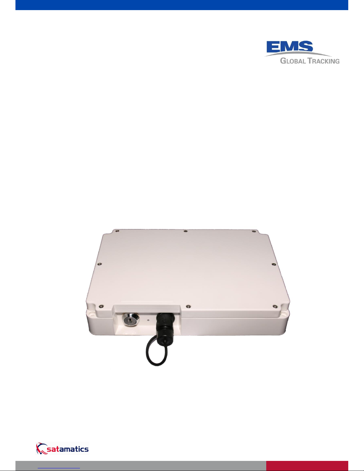
TAM-242/252/262
Installation and
Operating Manual
A ™ Product
Page 2

TAM-242/252/262 Installation and Operating Manual
This document contains information that is proprietary and confidential to EMS Global Tracking (one or more of the following: EMS Global Tracking Ltd and EMS Technologies
Canada, Ltd), and is supplied on the express condition that it is not to be used for any purpose other than the purpose for which it was issued, nor is it to be copied or
communicated in whole or in part, to any third party other than the recipient organization, without the prior written permission of EMS Global Tracking.
© 2011 EMS Global Tracking Ltd, EMS Technologies Canada Ltd. MAN-0059 Issue 4
© EMS Global Tracking 2011
All rights reserved. No part of this publication may be reproduced in any form without the written permission of
EMS Global Tracking.
This document is issued in confidence for the purpose only for which it is supplied. Information in this document
is subject to change without notice. EMS Global Tracking makes no warranty of any kind with regards to this
material, including, but not limited to, the implied warranties of merchantability and fitness for purpose. EMS
Global Tracking shall not be liable for errors contained herein or for incidental or consequential damages in
connection with the use of this material. No part of this document may be photocopied, reproduced, or translated
to another language without prior written consent of EMS Global Tracking.
Satamatics and EMS are registered trademarks of EMS Global Tracking. All other trademarks belong to their
respective owners.
Any comments about this product or this manual should be addressed to:
EMS Global Tracking Ltd, Miller Court, Severn Drive, Tewkesbury Business Park, Tewkesbury, Gloucestershire,
GL20 8DN, United Kingdom
Telephone: +44 (0)1684 278616 email: trackingsupport@emsglobaltracking.com
Web: www.emsglobaltracking.com
TAM-242/252/262 Installation and Operator Manual
Document Number: MAN-0059 Issue 4
WASTE-ELECTRICAL AND ELECTRONIC EQUIPMENT (WEEE) DIRECTIVE
The European Parliament and the Council of the European Union have issued the Waste Electrical and
Electronic Equipment Directive. The purpose of the Directive is the prevention of waste of electrical and electronic
equipment, and to promote the re-use and recycling and other forms of recovery of such waste. As such the
Directive concerns producers, distributors and consumers.
The WEEE directive requires that both manufacturers and end users dispose of electrical and electronic
equipment and parts in an environmentally safe manner and that equipment and waste are re-used or recovered
for their materials or energy.
Electrical and electronic equipment and parts must not be disposed of with ordinary household refuse. All
electrical and electronic equipment and parts must be collected and disposed of separately. Products and
equipment that must be collected for re-use, recycling and other forms of recovery are marked with the pictogram
shown in above.
When disposing of electrical and electronic equipment by use of the collection systems available in your country,
you protect the environment, human health and contribute to the prudent and rational use of natural resources.
Collecting electrical and electronic equipment and waste prevents the potential contamination of nature with the
hazardous substances that may be present in electrical and electronic products and equipment.
Your Dealer/Distributor will assist and advise you of the correct way of disposal in your country.
Amendment Record
Issue
Description
1
Initial Issue
2
Updated battery safety information, added expected lifetime table, added charging time.
Note added in chapter 4 about storage temperature.
3
Updated to include TAM-252 information.
Change to battery life estimates. Declaration of Conformity added.
4
Updated to include TAM-262 information.
Change to TAM-252 script behaviour.
Correction to battery alarm threshold – it is 10% of capacity instead of 25%.
Page 3

TAM-242/252/262 Installation and Operating Manual Contents
This document contains information that is proprietary and confidential to EMS Global Tracking (one or more of the following: EMS Global Tracking Ltd and EMS Technologies
Canada, Ltd), and is supplied on the express condition that it is not to be used for any purpose other than the purpose for which it was issued, nor is it to be copied or
communicated in whole or in part, to any third party other than the recipient organization, without the prior written permission of EMS Global Tracking.
MAN-0059 Issue 4 © 2011 EMS Global Tracking Ltd, EMS Technologies Canada Ltd. i
0Contents
0 Contents .................................................................................................... i
1 Preface ..................................................................................................... iii
General Safety Warnings .............................................................................................................. iii
Batty Safety .............................................................................................................................. iii
2 Chapter 1 - Unpacking .............................................................................. 1
Items Supplied ............................................................................................................................... 1
Items not Supplied ......................................................................................................................... 1
3 Chapter 2 – Introduction ........................................................................... 2
What is the TAM-242? ................................................................................................................... 2
TAM-242 Main Module .............................................................................................................. 2
Interface Connector, Key Switch, and LED .............................................................................. 2
Battery Pack .............................................................................................................................. 3
Reporting Interval ...................................................................................................................... 3
Switch On Reporting ................................................................................................................. 3
Receive Window ....................................................................................................................... 3
Battery Low Threshold .............................................................................................................. 3
Quality of Service ...................................................................................................................... 4
Limitations on Intended Operating Environment ...................................................................... 4
What is the TAM-252? ................................................................................................................... 4
TAM-252 Proximity switch and actuator ................................................................................... 4
Proximity switch status reporting .............................................................................................. 4
What is the TAM-262? ................................................................................................................... 5
TAM-262 panic button ............................................................................................................... 5
Panic button status reporting .................................................................................................... 5
4 Chapter 3 – Installation ............................................................................. 6
Pre-Installation Survey ................................................................................................................... 6
Location ..................................................................................................................................... 6
Mounting ......................................................................................................................................... 7
TAM-252 Proximity Switch ............................................................................................................. 8
Key Switch Operation..................................................................................................................... 9
Switching On the Terminal ........................................................................................................ 9
Switching Off the Terminal ........................................................................................................ 9
Operational Status .......................................................................................................................10
Troubleshooting ...........................................................................................................................11
Non Reception of Transmissions ............................................................................................11
LED Always Off .......................................................................................................................11
LED Continuous Red or Orange .............................................................................................11
5 Chapter 4 – Maintenance........................................................................ 12
Charging the Battery ....................................................................................................................12
6 Appendix A - Specifications .................................................................... 13
7 Appendix B – Warranty ........................................................................... 15
Warranty .......................................................................................................................................15
Limitation of Warranty .............................................................................................................15
Page 4

Preface TAM-242/252/262 Installation and Operating Manual
This document contains information that is proprietary and confidential to EMS Global Tracking (one or more of the following: EMS Global Tracking Ltd and EMS Technologies
Canada, Ltd), and is supplied on the express condition that it is not to be used for any purpose other than the purpose for which it was issued, nor is it to be copied or
communicated in whole or in part, to any third party other than the recipient organization, without the prior written permission of EMS Global Tracking.
ii © 2011 EMS Global Tracking Ltd, EMS Technologies Canada Ltd. MAN-0059 Issue 4
Governing Law ........................................................................................................................ 16
Returns ................................................................................................................................... 16
8 Appendix C – Declaration of Conformity .................................................. 17
Page 5
TAM-242/252/262 Installation and Operating Manual Contents
This document contains information that is proprietary and confidential to EMS Global Tracking (one or more of the following: EMS Global Tracking Ltd and EMS Technologies
Canada, Ltd), and is supplied on the express condition that it is not to be used for any purpose other than the purpose for which it was issued, nor is it to be copied or
communicated in whole or in part, to any third party other than the recipient organization, without the prior written permission of EMS Global Tracking.
MAN-0059 Issue 4 © 2011 EMS Global Tracking Ltd, EMS Technologies Canada Ltd. iii
Preface
General Safety Warnings
WARNING: This device contains static sensitve parts. There are no user-serviceable
parts or fuses inside this device. Refer servicing only to qualified service personnel.
WARNING: This product contains magnetized material. Due care should be taken
when handling fully magnetized material as physical personal injury may occur by the
inadvertent attraction of magnetized material to other similar or ferro-magnetic material.
WARNING: Close proximity (less than 100mm) to the magnetized material may affect
the operation of heart pacemakers.
Batty Safety
WARNING: This product contains a rechargeable battery pack. To prevent physical
injury, observe the following:
Do not short circuit.
Do not incinerate.
Do not dispose of in fire.
Only recharge the battery using the supplied charger.
CAUTION: THERE IS THE RISK OF EXPLOSION IF THE BATTERY PACK IS
REPLACED BY ONE THAT IS NOT SUPPLIED BY EMS GLOBAL TRACKING, OR
IF THE BATTERY PACK IS ABUSED OR DISPOSED OF INCORRECTLY.
Local and International regulations regarding the transport of batteries must be complied with. In
particular, all packaging must be UN3090 approved. Contact
trackingsupport@emsglobaltracking.com for further information.
Note:
Retain this manual for future reference.
Observe all warnings on the equipment and in this manual.
Follow all installation and operating instructions.
Maximum Permissible Exposure (MPE) limits – This equipment complies with FCC (OET
bulletin 65) general population/uncontrolled exposure limits as applied to RF energy from a
Mobile device. (A mobile device being defined as a transmitting device designed to be used
in other than fixed locations and to be generally used in such a way that a separation
distance of at least 20 centimetres is normally maintained between the transmitter’s
radiating structures and the body of the user or nearby persons.
Page 6

Page 7

TAM-242/252/262 Installation and Operating Manual Unpacking
This document contains information that is proprietary and confidential to EMS Global Tracking (one or more of the following: EMS Global Tracking Ltd and EMS Technologies
Canada, Ltd), and is supplied on the express condition that it is not to be used for any purpose other than the purpose for which it was issued, nor is it to be copied or
communicated in whole or in part, to any third party other than the recipient organization, without the prior written permission of EMS Global Tracking.
MAN-0059 Issue 4 © 2011 EMS Global Tracking Ltd, EMS Technologies Canada Ltd. 1 of 17
1Chapter 1 - Unpacking
Caution: The equipment must be transported to the final installation site fully packed (as originally
supplied) to avoid damage. Failure to transport the equipment with the correct packaging may
invalidate any warranty claims.
All packaging should be retained until the equipment is installed on site and working correctly.
Items Supplied
The TAM-242 (part number A142Bxx1) equipment is supplied with the following:
B104B01 or B104B03 – Main Enclosure Assembly.
01708 – Adhesive Pad (qty 4)
The TAM-252 (part number A151Bxx) equipment is supplied with the following:
B104B03 – Main Enclosure Assembly.
01708 – Adhesive Pad (qty 4)
A159B01 – Alert Switch Cable 5m, actuator and mounting plates
The TAM-262 (part number A167Bxx) equipment is supplied with the following:
B104B03 – Main Enclosure Assembly.
01708 – Adhesive Pad (qty 4)
A166B01 – Panic Button Cable 3m
Items not Supplied
A147B01 – Single Charger
A148B01 – Ten way charger
MAN-0059 – TAM-242 & TAM-252 Installation & Operating Manual
1
The ‘xx’ in the part number represents a 2-digit numerical value that will vary depending on the default configuration
of the unit. Contact trackingsupport@emsglobaltracking.com for more information on unit configurations.
Page 8

Introduction TAM-242/252/262 Installation and Operating Manual
This document contains information that is proprietary and confidential to EMS Global Tracking (one or more of the following: EMS Global Tracking Ltd and EMS Technologies
Canada, Ltd), and is supplied on the express condition that it is not to be used for any purpose other than the purpose for which it was issued, nor is it to be copied or
communicated in whole or in part, to any third party other than the recipient organization, without the prior written permission of EMS Global Tracking.
2 of 17 © 2011 EMS Global Tracking Ltd, EMS Technologies Canada Ltd. MAN-0059 Issue 4
2Chapter 2 – Introduction
What is the TAM-242?
The TAM-242 (Figure 2-1) is a compact, low data rate, satellite terminal designed to operate over the
INMARSAT satellites for use in tracking assets that have no integral power source. The terminal uses
the INMARSAT IsatM2M protocol and provides global coverage and fully automatic roaming across
all of the world’s ocean regions, see Location on page 6 for more information.
Figure 2-1: TAM-242 Tracking and Monitoring Equipment
TAM-242 Main Module
The TAM-242 incorporates a SAT-200 satellite modem mounted within the IP66 rated enclosure,
containing the battery compartment and interface PCB.
The TAM-242 may either be permanently fitted to the asset or temporarily deployed utilising the four
(4) magnets incorporated within the enclosure base.
Interface Connector, Key Switch, and LED
The TAM-242 has one external interface connector which is used to charge the unit and a key switch
that allows you to switch the terminal “On” and “Off”. This helps preserve the life of the battery when
the terminal is not in use. Further instructions on the use of the key switch are contained in Key
Switch Operation on page 8.
Page 9

TAM-242/252/262 Installation and Operating Manual Introduction
This document contains information that is proprietary and confidential to EMS Global Tracking (one or more of the following: EMS Global Tracking Ltd and EMS Technologies
Canada, Ltd), and is supplied on the express condition that it is not to be used for any purpose other than the purpose for which it was issued, nor is it to be copied or
communicated in whole or in part, to any third party other than the recipient organization, without the prior written permission of EMS Global Tracking.
MAN-0059 Issue 4 © 2011 EMS Global Tracking Ltd, EMS Technologies Canada Ltd. 3 of 17
The TAM-242 incorporates a Light Emitting Diode (LED) which indicates the unit’s status. During
normal operations the LED intermittently flashes when the terminal is either transmitting a message
or awaiting receipt of one. Once the terminal returns to “sleep” mode, the LED will cease flashing.
During charging the LED will indicate the charge status of the battery. See Operational Status on
page 10 for a description of the LED functions.
Battery Pack
The battery pack is a rechargeable sealed unit. The operational time of the unit before requiring
recharging will be affected by the reporting interval between position reports. The remaining battery
capacity is calculated internally and the terminal will send a report that includes the status of the
battery with every position report. A Low Battery status will be activated when the remaining capacity
has fallen below 10% +/- 5%.
The table below gives some approximate life expectancies with the supplied battery; these do not
include the age of the battery and the effect of temperature on the battery and are provided only as
guidance for the user:
Reporting Interval
Lifetime
15 minutes
up to 4 weeks
1 hour
up to 10 weeks
6 hours
up to 6 months
Caution: Before recharging the unit ensure that the key switch is in the “off” position. See Charging
the Battery on page 12 for more information.
Reporting Interval
The Reporting Interval is the time between position reports, providing the GPS position of the asset,
as well as other information such as battery status. Changing the reporting interval will affect the
operational time between charges.
Switch On Reporting
Every time that the key switch is used to switch on the TAM-242, a position report will be sent to
confirm correct operation, provided that the terminal can see the sky within 10 minutes of the power
being applied. Position reporting will then continue at the programmed reporting interval.
Receive Window
After each routine position report, the terminal will enter “sleep” mode to conserve battery power. It
will be unable to receive messages during this mode.
The terminal will “wake” up each day at approximately 1045 hrs UTC to enable it to receive any
messages sent from the application.
Battery Low Threshold
The Battery Low alarm occurs typically when the battery reaches 10% +/- 5% charge capacity.
Page 10

Introduction TAM-242/252/262 Installation and Operating Manual
This document contains information that is proprietary and confidential to EMS Global Tracking (one or more of the following: EMS Global Tracking Ltd and EMS Technologies
Canada, Ltd), and is supplied on the express condition that it is not to be used for any purpose other than the purpose for which it was issued, nor is it to be copied or
communicated in whole or in part, to any third party other than the recipient organization, without the prior written permission of EMS Global Tracking.
4 of 17 © 2011 EMS Global Tracking Ltd, EMS Technologies Canada Ltd. MAN-0059 Issue 4
Quality of Service
The TAM-242 has been designed so that the battery connection time randomises the start of position
reporting. This maintains a high quality of service by avoiding network congestion which could occur
with synchronised reporting across a population. Position reports for each TAM-242 will still arrive at
the programmed reporting interval.
Limitations on Intended Operating Environment
Guidance notes for the installation and use of the TAM-242 must be strictly followed. EMS Global
Tracking exercises due diligence to ensure that the equipment is suitable for use, but ultimate
responsibility for the compliance of a complete system rests with the installer and operator.
What is the TAM-252?
The TAM-252 is a TAM-242 supplied with a magnetic proximity switch and actuator which can be
used to monitor a moving object, such as a door.
TAM-252 Proximity switch and actuator
The proximity switch is mounted on the end of a cable that mates with the front panel connector on
the TAM-242 unit. The actuator is a separate item that must be mounted so that in normal operation
it is located next to the proximity switch.
Figure 2-2: TAM-252 Proximity switch and actuator
Proximity switch status reporting
When supplied as part of a TAM-252 kit, the TAM-242 unit will report the status of the proximity
switch (OPEN or CLOSED). The switch is CLOSED when the actuator is mounted correctly next to
the switch. The switch is OPEN when the actuator is not close enough to the switch, when the switch
cable is not mated to the TAM-242 unit or when the switch cable is cut. When the switch status
changes from CLOSED to OPEN, an extra position report is generated and an ‘Alert’ flag is set in the
message. The TAM-242 will then generate further Alert messages for the next 4 hours at the defined
Alert reporting interval. After 4 hours the unit will revert back to standard tracking messages at the
normal reporting interval.
Page 11

TAM-242/252/262 Installation and Operating Manual Introduction
This document contains information that is proprietary and confidential to EMS Global Tracking (one or more of the following: EMS Global Tracking Ltd and EMS Technologies
Canada, Ltd), and is supplied on the express condition that it is not to be used for any purpose other than the purpose for which it was issued, nor is it to be copied or
communicated in whole or in part, to any third party other than the recipient organization, without the prior written permission of EMS Global Tracking.
MAN-0059 Issue 4 © 2011 EMS Global Tracking Ltd, EMS Technologies Canada Ltd. 5 of 17
What is the TAM-262?
The TAM-262 is a TAM-242 supplied with a panic button on the end of a 3m long cable.
TAM-262 panic button
The panic button is mounted on the end of a cable that mates with the front panel connector on the
TAM-242 unit. See Figure 2-3.
Figure 2-3: TAM-262 Panic button cable
Panic button status reporting
When supplied as part of a TAM-262 kit, the TAM-242 unit will enter an Alert state based on the state
of the panic button. The switch is normally CLOSED and changes to an OPEN state when the switch
is pressed. When the switch status changes from CLOSED to OPEN, an extra position report is
generated and an ‘Alert’ flag is set in the message. The TAM-242 will then generate further Alert
messages for the next 4 hours at the defined Alert reporting interval. After 4 hours the unit will revert
back to standard tracking messages at the normal reporting interval.
Page 12

Installation TAM-242/252/262 Installation and Operating Manual
This document contains information that is proprietary and confidential to EMS Global Tracking (one or more of the following: EMS Global Tracking Ltd a nd EMS Technologies
Canada, Ltd), and is supplied on the express condition that it is not to be used for any purpose other than the purpose for which it was issued, nor is it to be copied or
communicated in whole or in part, to any third party other than the recipient organization, without the prior written permission of EMS Global Tracking.
6 of 17 © 2011 EMS Global Tracking Ltd, EMS Technologies Canada Ltd. MAN-0059 Issue 4
3Chapter 3 – Installation
WARNING: Installation and service should be carried out only by suitably qualified
service personnel. Local working practices and regulations for wiring and installations
must be adhered to.
WARNING: Refer to General Safety Warnings on page iii before installing or handling
this product.
Note: The TAM-242 must be fully charged before deployment to enable accurate reporting of the
remaining battery charge capacity, see Charging the Battery on page 12 for more information.
Note: The TAM-242 must be activated with a valid airtime package and also registered on the
application website prior to installation.
Note: If you have not already done so, record the ISN and serial number located on the bottom of the
TAM-242. This will be required for registration and warranty enquiries.
Pre-Installation Survey
Before attempting to install the equipment, it is essential that a full survey of the proposed location is
carried out and the following points taken into account. Failure to do so could result in the system
malfunctioning.
Location
The TAM-242 should be located with an unobstructed, clear view of the sky.
The TAM-242 should be mounted on a flat horizontal surface.
The connector and key switch side of the TAM-242 must face the opposite direction of
travel of the asset.
Consider the position of the satellites (Figure 3-1). The Inmarsat satellites are in geo-
stationary orbits above the equator. In the Northern hemisphere the satellites are located to
the south, in the Southern hemisphere the satellites are located to the North. The further
away from the Equator the asset is, the lower the angle of elevation will be above the
horizon.
The TAM-242 should be located on the highest point possible, free from obstructions and
safe from damage during normal operation.
Page 13

TAM-242/252/262 Installation and Operating Manual Installation
This document contains information that is proprietary and confidential to EMS Global Tracking (one or more of the following: EMS Global Tracking Ltd and EMS Technologies
Canada, Ltd), and is supplied on the express condition that it is not to be used for any purpose other than the purpose for which it was issued, nor is it to be copied or
communicated in whole or in part, to any third party other than the recipient organization, without the prior written permission of EMS Global Tracking.
MAN-0059 Issue 4 © 2011 EMS Global Tracking Ltd, EMS Technologies Canada Ltd. 7 of 17
For installations exposed to shock and/or vibration, use a mounting scheme that isolates
the unit from the excessive shock and/or vibration.
Choose a location that is not near other satellite communication equipment, and/or
microwave dishes to prevent RF jamming.
It is advisable to leave at least a 1 meter separation between the system and any other
communications devices.
Avoid mounting on a hot surface.
Figure 3-1: Inmarsat Satellite Constellation
Mounting
Caution: The TAM-242 must be mounted so that the key switch and connector side of the TAM-242
is facing in the opposite direction to the direction of travel of the asset being tracked.
The mounting position should take into account the criteria defined in Location on page 6. If the
terminal is to be permanently fitted then all four mounting points must be use. The four mounting
points are M4 clearance holes on a 230.3mm x 161.3mm rectangle, with the enclosure overhanging
these fixings by around 10mm on all sides. Fit the adhesive pads to the face of each magnet to
protect against damage to the asset.
Caution: Do not over tighten the fixing points, doing so may cause damage to the TAM-242.
Page 14

Installation TAM-242/252/262 Installation and Operating Manual
This document contains information that is proprietary and confidential to EMS Global Tracking (one or more of the following: EMS Global Tracking Ltd a nd EMS Technologies
Canada, Ltd), and is supplied on the express condition that it is not to be used for any purpose other than the purpose for which it was issued, nor is it to be copied or
communicated in whole or in part, to any third party other than the recipient organization, without the prior written permission of EMS Global Tracking.
8 of 17 © 2011 EMS Global Tracking Ltd, EMS Technologies Canada Ltd. MAN-0059 Issue 4
TAM-252 Proximity Switch
The switch and actuator must be mounted as shown below to ensure that the switch is closed. The
gap between the switch and actuator must be less than 6mm. The switch will open when the gap is
greater than 13mm. Care must be taken during installation to ensure that the switch and actuator are
installed in such a way that a separation of 6mm or less is maintained in order to prevent false
activation of the switch.
Optional mounting plates have been supplied for the switch and actuator. These can be used to
increase the separation between the switch/actuator and the surface they are mounted on. This is
useful when they are mounted on ferrous metals since the metal can affect the activation distance
between the switch and actuator.
Ensure that the proximity switch is mounted so that the cable is long enough to reach the TAM-242
unit.
Figure 3-2: Proximity switch mounting
Page 15

TAM-242/252/262 Installation and Operating Manual Installation
This document contains information that is proprietary and confidential to EMS Global Tracking (one or more of the following: EMS Global Tracking Ltd and EMS Technologies
Canada, Ltd), and is supplied on the express condition that it is not to be used for any purpose other than the purpose for which it was issued, nor is it to be copied or
communicated in whole or in part, to any third party other than the recipient organization, without the prior written permission of EMS Global Tracking.
MAN-0059 Issue 4 © 2011 EMS Global Tracking Ltd, EMS Technologies Canada Ltd. 9 of 17
Key Switch Operation
The key switch is used to turn the TAM-242 on or off for periods when the equipment is not in use
and thus preserve battery life.
Switching On the Terminal
Turn the key switch to the on position. When switching the terminal on, the LED will start to flash 1
second on, 2 seconds off until a position report has been sent or it has timed out (up to 10 minutes).
Figure 3-3: Key Switch On Position
Note: If the LED does not switch on as expected there may be a fault. Please refer to
Troubleshooting on page 11 for more information.
Switching Off the Terminal
Turn the key switch to the off position. The LED will switch on for 6 seconds then switch off. The
terminal is now in the off state and will not transmit position reports until switched back on.
Figure 3-4: Key Switch Off Position
Note: If the LED does not switch on as expected there may be a fault. Please refer to
Troubleshooting on page 11 for more information.
Page 16

Installation TAM-242/252/262 Installation and Operating Manual
This document contains information that is proprietary and confidential to EMS Global Tracking (one or more of the following: EMS Global Tracking Ltd a nd EMS Technologies
Canada, Ltd), and is supplied on the express condition that it is not to be used for any purpose other than the purpose for which it was issued, nor is it to be copied or
communicated in whole or in part, to any third party other than the recipient organization, without the prior written permission of EMS Global Tracking.
10 of 17 © 2011 EMS Global Tracking Ltd, EMS Technologies Canada Ltd. MAN-0059 Issue 4
Operational Status
The TAM-242 is a self contained unit and as such the only checks that can be made are when
charging the battery or changing the unit’s state from on to off or vice versa. In all of these cases the
LED function is as per the following table:
Operation
LED Status
Duration
Remarks
Normal Operation –
Position Reporting and
“Awake” to Receive
Message
Flashing –
Colour
indicates
charge level
One second on, two
seconds off for up to
10 minutes
The colour indicates the
charge status, Green >90%,
Orange 25% to 90%, Red
<25%. Terminal will enter
Sleep Mode between
transmissions (no LED)
Switch Off with Key
Switch
ON
Six seconds
LED will remain off until the
terminal is switched on or
charged
Switch On with Key
Switch
Flashing
One second on, two
seconds off for up to
10 minutes
Immediately transmits a
position report
Charging
ON – Red or
Orange
Continuous
There is a fault
Charging
Flashing - Red
Five seconds on, three
seconds off
Battery charge at <90%
Charging
Flashing Green
Five seconds on, three
seconds off
Battery charge at >90%
Charging
ON - Green
Continuous
Battery full
Page 17

TAM-242/252/262 Installation and Operating Manual Installation
This document contains information that is proprietary and confidential to EMS Global Tracking (one or more of the following: EMS Global Tracking Ltd and EMS Technologies
Canada, Ltd), and is supplied on the express condition that it is not to be used for any purpose other than the purpose for which it was issued, nor is it to be copied or
communicated in whole or in part, to any third party other than the recipient organization, without the prior written permission of EMS Global Tracking.
MAN-0059 Issue 4 © 2011 EMS Global Tracking Ltd, EMS Technologies Canada Ltd. 11 of 17
Troubleshooting
Non Reception of Transmissions
If the application is not receiving transmissions from the TAM-242, there may be a problem with the
system. You should:
Ensure that the TAM-242 has been activated with a valid airtime package.
Ensure that the antenna is not blocked and has a clear line of sight to the satellites. Refer to
Location on page 6.
Ensure that the TAM-242 is switched on.
Ensure that the battery is charged.
LED Always Off
If the LED does not switch on either during a normal transmission or as part of the sequence for
Switching on/off, the battery may be discharged. The LED will indicate the battery charge status
whilst the unit is plugged into the charger. If after checking the battery the fault persists you should
contact trackingsupport@emsglobaltracking.com for further help.
LED Continuous Red or Orange
In the event the LED illuminates red or orange continuously, there is most likely a fault with the unit.
Contact trackingsupport@emsglobaltracking.com for further help.
Page 18

Maintenance TAM-242/252/262 Installation and Operating Manual
This document contains information that is proprietary and confidential to EMS Global Tracking (one or more of the following: EMS Global Tracking Ltd and EMS Technologies
Canada, Ltd), and is supplied on the express condition that it is not to be used for any purpose other than the purpose for which it was issued, nor is it to be copied or
communicated in whole or in part, to any third party other than the recipient organization, without the prior written permission of EMS Global Tracking.
12 of 17 © 2011 EMS Global Tracking Ltd, EMS Technologies Canada Ltd. MAN-0059 Issue 4
4Chapter 4 – Maintenance
CAUTION: THERE IS THE RISK OF EXPLOSION IF THE BATTERY PACK IS
REPLACED BY ONE THAT IS NOT SUPPLIED BY EMS GLOBAL TRACKING, OR
IF THE BATTERY PACK IS ABUSED OR DISPOSED OF INCORRECTLY.
OBSERVE BATTERY SAFETY INFORMATION PRESENT UNDER GENERAL
SAFETY WARNINGS ON PAGE iii.
WARNING: The TAM-242 requires no specific maintenance. The device contains static
sensitive parts. There are no user-serviceable parts or fuses inside the device. Refer
servicing only to qualified service personnel.
Note: Prolonged storage of the unit at high temperatures may cause premature ageing of the battery,
resulting in a reduced battery capacity. The unit should be stored below 40°C where possible.
Dust and finger marks can be removed using a soft damp cloth. Avoid using domestic cleaning
products.
Charging the Battery
Caution: The unit should only be recharged whilst the key switch is in the off position. The unit will
not transmit if switched on whilst recharging. Please refer to Switching Off the Terminal on page 9.
Caution: Only recharge using the supplied charger.
Note: The unit must be fully charged before deployment to enable accurate reporting of the
remaining battery charge capacity. Charging time for a discharged unit will typically be 6 to 8 hours.
To recharge the battery connect the unit to the charger. When discharged the charging time will
typically be 6 to 8 hours. Whilst the unit is charging the LED will either flash to indicate the battery
charge status, or illuminated solid red or orange to indicate a fault. Charge status is indicated as per
the following table:
LED Status
Battery Charge Level
Flashing - Red
Low <90%
Flashing - Green
Charged >90%
Please refer to Operational Status on page 10 for more information on the LED functions.
Page 19

TAM-242/252/262 Installation and Operating Manual Specifications
This document contains information that is proprietary and confidential to EMS Global Tracking (one or more of the following: EMS Global Tracking Ltd and EMS Technologies
Canada, Ltd), and is supplied on the express condition that it is not to be used for any purpose other than the purpose for which it was issued, nor is it to be copied or
communicated in whole or in part, to any third party other than the recipient organization, without the prior written permission of EMS Global Tracking.
MAN-0059 Issue 4 © 2011 EMS Global Tracking Ltd, EMS Technologies Canada Ltd. 13 of 17
5Appendix A - Specifications
Physical
Dimensions 247 mm x 178 mm x 48 mm
Weight 1.3kg
Environmental
Temperature (TAM-242) -35ºC to +55ºC
Temperature (TAM-252)2 -20ºC to +55ºC
Charging Temperature 0ºC to +45ºC
Humidity ≤ 95% @ +40ºC, non-condensing
SAT-200 Modem
Transmit frequency 1626.5 MHz to 1660.5 MHz
Receive frequency 1525.0 MHz to 1559.0 MHz
GPS frequency 1575.42 ± 1.0 MHz
Elevation angle range 0º to 90º
Transmit EIRP 0 - 9dBW
Transmitter modulation 2 level FSK, 256Hz tone spacing
Transmit burst duration 2s or 8s
Receiver
Receive G/T ≥ -25dB/K at EL = 30º
Receiver modulation 32-ary FSK, 20Hz tone spacing
GPS
Channels 50
Time To First Fix (Typical) Cold start: 29s
Hot start: <1s (GPS was off for less than 2 hours)
Accuracy (SA Off) Position (CEP, 2D): 2.5m (Typical)
Altitude Maximum 12000m
Dynamic capability Velocity: Maximum 310m/s
Acceleration: ≤ 4g
Maximum update rate 1s
Control & Monitoring
Interface Asynchronous serial RS232
Baud rate 9600 bps
Parity/data bits/stop bits N,8,1
2
The TAM-252 temperature specification is limited by the temperature specification of the proximity switch.
Page 20

Specifications TAM-242/252/262 Installation and Operating Manual
This document contains information that is proprietary and confidential to EMS Global Tracking (one or more of the following: EMS Global Tracking Ltd and EMS Technologies
Canada, Ltd), and is supplied on the express condition that it is not to be used for any purpose other than the purpose for which it was issued, nor is it to be copied or
communicated in whole or in part, to any third party other than the recipient organization, without the prior written permission of EMS Global Tracking.
14 of 17 © 2011 EMS Global Tracking Ltd, EMS Technologies Canada Ltd. MAN-0059 Issue 4
Approvals and Certification
1999/5/EC including 2004/108/EC EMC and 2006/95/EC LVD
Relevant Standards:
EN301 489-20 v1.2.1 (2002-11) EMC Testing
EN 60950:2000 Electrical Safety (R&TTE)
ETSI EN 301 426 v1.2.1 (2001-10) Radio Approval
Ingress Protection:
EN60529 :1999 classification IP66
Inmarsat Type Approved (Inmarsat Certificate Number DST005)
The product complies with FCC requirements:
FCC 25.216
FCC 25.202
OET bulletin 65
Page 21

TAM-242/252/262 Installation and Operating Manual Specifications
This document contains information that is proprietary and confidential to EMS Global Tracking (one or more of the following: EMS Global Tracking Ltd and EMS Technologies
Canada, Ltd), and is supplied on the express condition that it is not to be used for any purpose other than the purpose for which it was issued, nor is it to be copied or
communicated in whole or in part, to any third party other than the recipient organization, without the prior written permission of EMS Global Tracking.
MAN-0059 Issue 4 © 2011 EMS Global Tracking Ltd, EMS Technologies Canada Ltd. 15 of 17
6Appendix B – Warranty
Warranty
EMS Global Tracking warrants that the TAM-242 will be free from defects in material and
workmanship for a period of one (1) year from date of purchase only if the instructions in this
document have been complied with and the installation has been carried out by an authorized
person. During the warranty period EMS Global Tracking will, at its option, either repair or replace
products that prove to be defective. If a defect exists, at its option, EMS Global Tracking will repair
the product at no charge, using new or refurbished replacement parts, or exchange the product with a
product that is new or which has been manufactured from new or serviceable used parts and is at
least functionally equivalent to the original product. A replacement product assumes the remaining
warranty of the original product or 90 days, whichever is the longer for you. All hardware (or part
thereof) that is replaced by EMS Global Tracking shall become the property of EMS Global Tracking
upon replacement. EMS Global Tracking does not warrant that the operation of the equipment or
firmware will be uninterrupted or error free.
For warranty service or repair the product must be returned to a service facility designated by EMS
Global Tracking quoting the information contained in Section 4. Failure to do so could invalidate or
delay any warranty repair.
Limitation of Warranty
The foregoing warranty shall not apply to defects resulting from improper or inadequate maintenance
by the Buyer, Buyer-supplied software (scripts) or interfacing, unauthorized modification or misuse,
operation outside of the environmental specifications for the product, or improper installation. The
warranty shall not apply if batteries other than those supplied by or recommended by EMS Global
Tracking are used. The warranty shall not apply if an unauthorized person has installed the system.
EXCEPT FOR THE ONE (1) YEAR LIMITED WARRANTY SPECIFIED HEREIN, THE PRODUCT IS
PROVIDED “AS-IS” WITHOUT ANY WARRANTY OF ANY KIND INCLUDING, WITHOUT
LIMITATION, ANY WARRANTY OF MERCHANTABILITY, FITNESS FOR A PARTICULAR
PURPOSE AND NON-INFRINGEMENT. IF ANY IMPLIED WARRANTY CANNOT BE
DISCLAIMED IN ANY TERRITORY WHERE A PRODUCT IS SOLD, THE DURATION OF SUCH
IMPLIED WARRANTY SHALL BE LIMITED TO NINETY (90) DAYS. EXCEPT AS EXPRESSLY
COVERED UNDER THE LIMITED WARRANTY PROVIDED HEREIN, THE ENTIRE RISK AS TO
THE QUALITY, SELECTION AND PERFORMANCE OF THE PRODUCT IS WITH THE
PURCHASER OF THE PRODUCT.
TO THE MAXIMUM EXTENT PERMITTED BY LAW, EMS GLOBAL TRACKING IS NOT
LIABLE UNDER ANY CONTRACT, NEGLIGENCE, STRICT LIABILITY OR OTHER
LEGAL OR EQUITABLE THEORY FOR ANY LOSS OF USE OF THE PRODUCT,
INCONVENIENCE OR DAMAGES OF ANY CHARACTER, WHETHER DIRECT,
SPECIAL, INCIDENTAL OR CONSEQUENTIAL (INCLUDING, BUT NOT LIMITED TO,
DAMAGES FOR LOSS OF GOODWILL, WORK STOPPAGE, COMPUTER FAILURE
OR MALFUNCTION, LOSS OF INFORMATION OR DATA CONTAINED IN, STORED
ON, OR INTEGRATED WITH ANY PRODUCT RETURNED TO EMS GLOBAL
TRACKING FOR WARRANTY REPAIR) RESULTING FROM THE USE OF THE
Page 22

Specifications TAM-242/252/262 Installation and Operating Manual
This document contains information that is proprietary and confidential to EMS Global Tracking (one or more of the following: EMS Global Tracking Ltd and EMS Technologies
Canada, Ltd), and is supplied on the express condition that it is not to be used for any purpose other than the purpose for which it was issued, nor is it to be copied or
communicated in whole or in part, to any third party other than the recipient organization, without the prior written permission of EMS Global Tracking.
16 of 17 © 2011 EMS Global Tracking Ltd, EMS Technologies Canada Ltd. MAN-0059 Issue 4
PRODUCT, RELATING TO WARRANTY SERVICE, OR ARISING OUT OF ANY
BREACH OF THIS LIMITED WARRANTY, EVEN IF EMS GLOBAL TRACKING HAS
BEEN ADVISED OF THE
POSSIBILITY OF SUCH DAMAGES. THE SOLE REMEDY FOR A BREACH OF THE FOREGOING
LIMITED WARRANTY IS REPAIR OR REPLACEMENT OF THE DEFECTIVE OR NONCONFORMING PRODUCT.
Governing Law
The laws of England and Wales shall govern this one (1) year warranty. Some countries do not allow
the exclusion or limitation of incidental or consequential damages or exclusions or limitations on the
duration of implied warranties or conditions. The above limitations may not therefore apply to you.
This warranty gives you specific legal rights, and you may also have rights that vary by country.
Returns
If you are advised to return your equipment, you will be provided with a Return Materials
Authorization (RMA) number, which must be quoted on all supporting paperwork. You must also
include the Inmarsat Serial Number (ISN), part number and product serial number. Failure to do so
could result in a delay in processing the repair.
Page 23

TAM-242/252/262 Installation and Operating Manual DofC
This document contains information that is proprietary and confidential to EMS Global Tracking (one or more of the following: EMS Global Tracking Ltd and EMS Technologies
Canada, Ltd), and is supplied on the express condition that it is not to be used for any purpose other than the purpose for which it was issued, nor is it to be copied or
communicated in whole or in part, to any third party other than the recipient organization, without the prior written permission of EMS Global Tracking.
MAN-0059 Issue 4 © 2011 EMS Global Tracking Ltd, EMS Technologies Canada Ltd. 17 of 17
7Appendix C – Declaration of Conformity
 Loading...