

Page 1
SYSTEM 7000
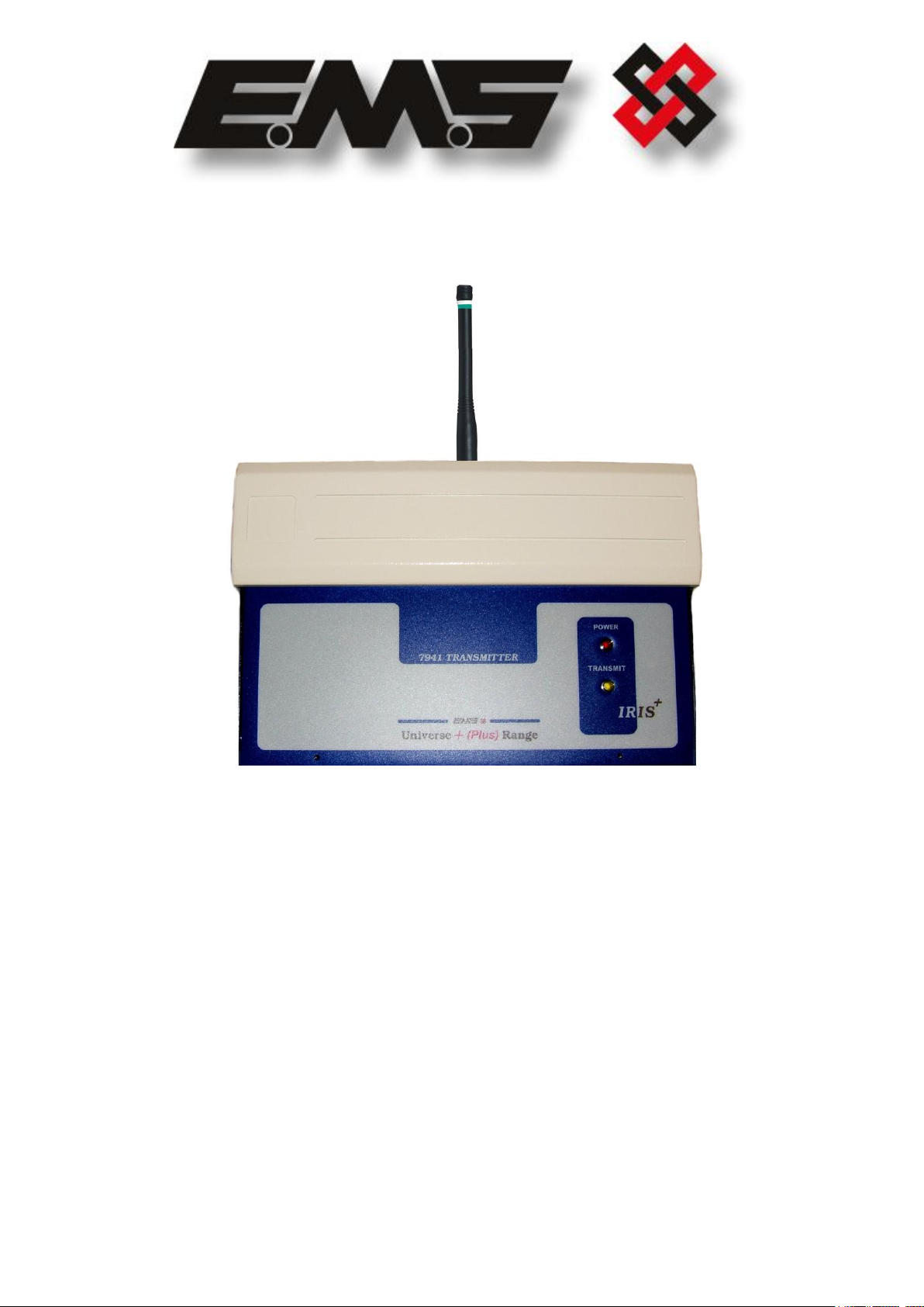
7941
EIGHT INPUT
HIGH POWERED
UHF TRANSMITTER
INSTALLATION AND PROGRAMMING
INSTRUCTIONS
Page 2

EMS SYSTEM 7000
2
Table of Contents
Section Page No
1. INTRODUCTION ................................................................................................ 3
2. TOOLS & TEST EQUIPMENT ................................................................................ 3
3. EQUIPMENT REQUIRED: .................................................................................... 3
4. PROGRAMMING CONNECTION DETAILS ............................................................... 6
5. INPUT PROGRAMMING ....................................................................................... 7
6. ID .................................................................................................................. 15
7. CON ............................................................................................................... 15
8. TYPE .............................................................................................................. 16
9. MODE ............................................................................................................. 17
10. TXD .............................................................................................................. 18
11. QUIT ............................................................................................................ 18
12. LOAD DEFAULT VALUES .................................................................................. 19
13. INTERNAL INPUT WIRING ............................................................................... 20
14. ADDING AN INPUT (HAND PUSH MODE) INTO THE IRIS RADIO RECEIVER ............ 21
15. ADDING AN INPUT (CONTACT MODE) INTO THE IRIS RADIO RECEIVER ............... 23
16. ADDING A RESET INPUT (HAND PUSH MODE) INTO THE IRIS RADIO RECEIVER .... 25
17. ASSIGNING TEXT DESCRIPTION FOR AN INPUT ................................................. 27
©2015 EMS Security Group Ltd. All rights reserved. TSD248 Iss 2 25/06/15 AJM
Page 3

EMS SYSTEM 7000
3
INPUT NUMBER
TYPE
INPUT ORIENTATION
1
Alarm
Normally Closed
2
Alarm
Normally Closed
3
Alarm
Normally Closed
4
Alarm
Normally Closed
5
Alarm
Normally Closed
6
Alarm
Normally Closed
7
Alarm
Normally Closed
8
Alarm
Normally Closed
7941 Eight Input Transmitter
7256 IRIS Receiver with standard 7200 software
7202 software will be required if the remote reset facility input is to be used.
Power Supply Units
Windows HyperTerminal with serial lead if programming changes are
required.
1. Introduction
1.1 The eight input UHF transmitter has been designed to operate in conjunction with
the EMS IRIS 7256 radio receiver. The transmitter unit is a 12 volt operated device
and comprises of a 500mW transmitter fitted with an additional printed circuit board
allowing the activation of eight opto isolated inputs. Each of the inputs can be
separately programmed into the IRIS receiver therefore allowing individual
identification via text descriptions. The inputs themselves can also be programmed
to operate either normally open or normally closed and the transmitted data from
the input can be selected from Alarm, Local, Tamper, Low Battery or Remote Reset.
1.2 As each input is opto isolated, a negative is required to be applied to one side of the
input. To trigger the input, a positive voltage should be applied if the contact is
programmed as normally open or removed if normally closed (see Figure 4 on page
19 for details). On an input activation a signal will be transmitted to the receiver
and displayed in the format programmed i.e. Alarm: Zone Area 1 for an input that
has been set as an Alarm input and programmed with the text description Zone
Area 1.
2. Tools & Test Equipment
2.1 Only standard hand tools are required to install the transmitter unit. The transmitter
is supplied with the inputs factory set as follows: -
If an inputs orientation requires alteration, Windows HyperTerminal with a serial a
lead will be required.
3. Equipment Required:
©2015 EMS Security Group Ltd. All rights reserved. TSD248 Iss 2 25/06/15 AJM
Page 4
EMS SYSTEM 7000
4
7941
Half Watt Txer
7941
Half Watt Txer
7941
Half Watt Txer
7256 IRIS+ Rxer
Eight Input Data
Transmissions
Eight Input Data
Transmissions
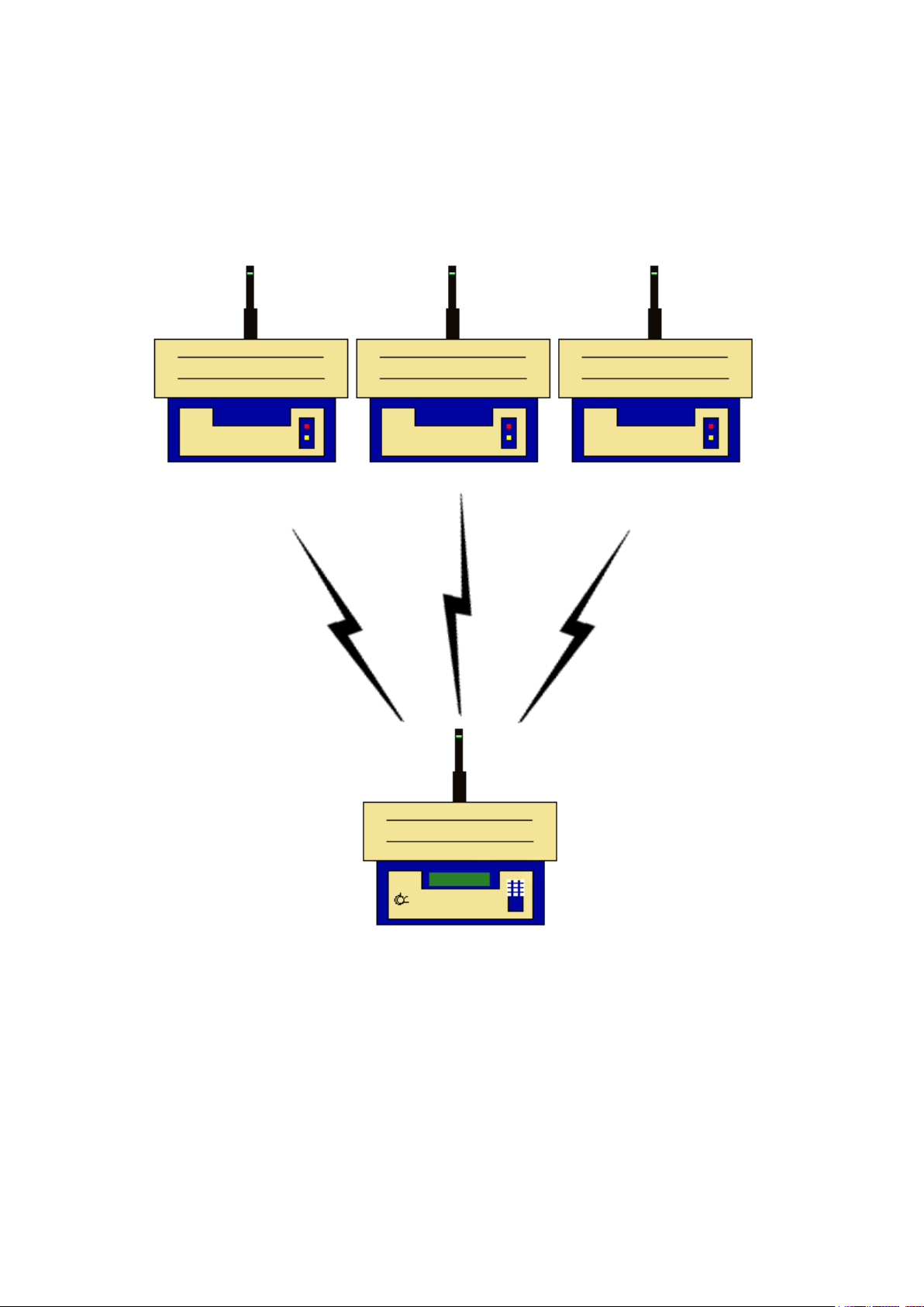
3.1 Remote devices and high gain aerials may also be required depending upon the
customers specification and requirements. Please note both the eight input
transmitter and the IRIS receiver will require an external power supply. Figure 1
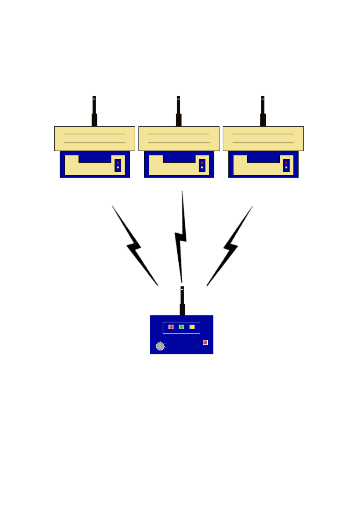
shows a typical IRIS radio system, whilst Figure 2 shows an alternative system
using a Single Channel 7703 Receiver: -
Figure 1
©2015 EMS Security Group Ltd. All rights reserved. TSD248 Iss 2 25/06/15 AJM
Page 5
EMS SYSTEM 7000
5
7941
Half Watt Txer
7941
Half Watt Txer
7941
Half Watt Txer
7703 Rxer
Eight Input Data
Transmissions
Eight Input Data
Transmissions
Figure 2
©2015 EMS Security Group Ltd. All rights reserved. TSD248 Iss 2 25/06/15 AJM
Page 6
EMS SYSTEM 7000
6
TAMPER
LOOP
0V 12V
DC
SUPPLY
COMMON
CONNECT
RX- RX+
RX TX COMMON
IN OUT CONNECT
ISOLATED RS485
ISOLATED RS232
2
3
5
+
-
TO
POWER
SUPPLY
9 PIN
SERIAL
CONNECTOR
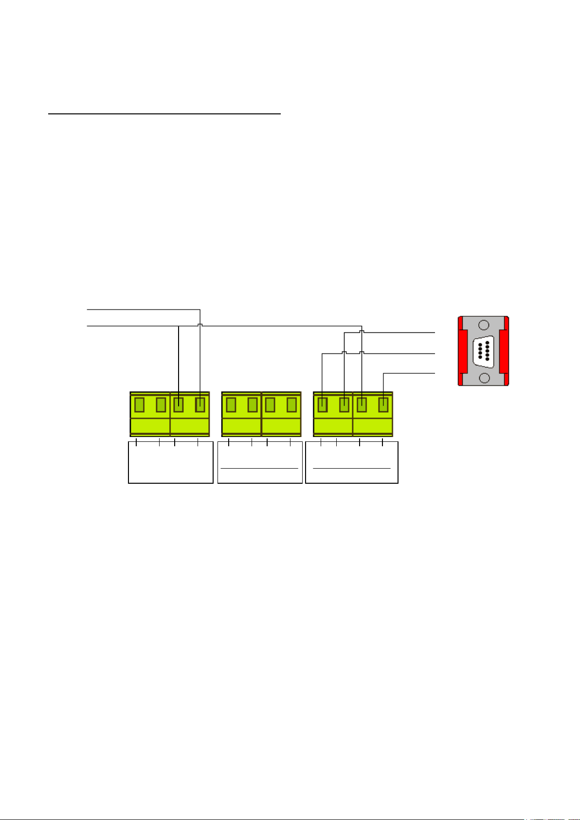
4. Programming Connection Details
4.1 The computer to transmitter physical connection details are as follows:-
COMPUTER ISOLATED RS 232 PORT
PIN 2 ---------------------------------- TX OUT
PIN 3 ---------------------------------- RX IN
PIN 5 ---------------------------------- COMMON CONNECT
4.2 All Computer to HyperTerminal connections are shown below in Figure 3.
Figure 3
©2015 EMS Security Group Ltd. All rights reserved. TSD248 Iss 2 25/06/15 AJM
Page 7
EMS SYSTEM 7000
7
5. Input Programming
5.1 The transmitter unit has the facility of allowing each of it’s inputs to be individually
configured. The settings for each input are as follows with the menu commands
required shown in brackets:- Inputs unique identification code (ID). Orientation of
the input to normally open or normally closed (CON). Inputs transmitted data on
activation, which ranges from Alarm, Local, Low Battery, Reset, Tamper and Not
Used (TYPE). Inputs mode of operation which can be selected between a contact
operated device which will also transmit input restored data or a hand push device
which must be used for certain types of transmitted data and does not transmit
restore data (MODE). A full explanation of all input settings and the operation of
the inputs if selected is described in more detail in the following paragraphs under
their menu commands headings.
5.2 The inputs have their settings defaulted to the following parameters: -
Inputs 1-8.............. ID: A0001-A0008
Con: Normally Closed
Type: Alarm
Mode: Current State
5.3 To allow access into the programming menu the computer should be set up using
windows HyperTerminal:-
PLEASE NOTE: Examples shown below are from Windows XP. Other
versions of Windows may vary.
To start a new HyperTerminal session, click on the ‘Start’ button.
Then select ‘Programs’ and then ‘Accessories’.
Now select ‘Communications’, then ‘HyperTerminal’.
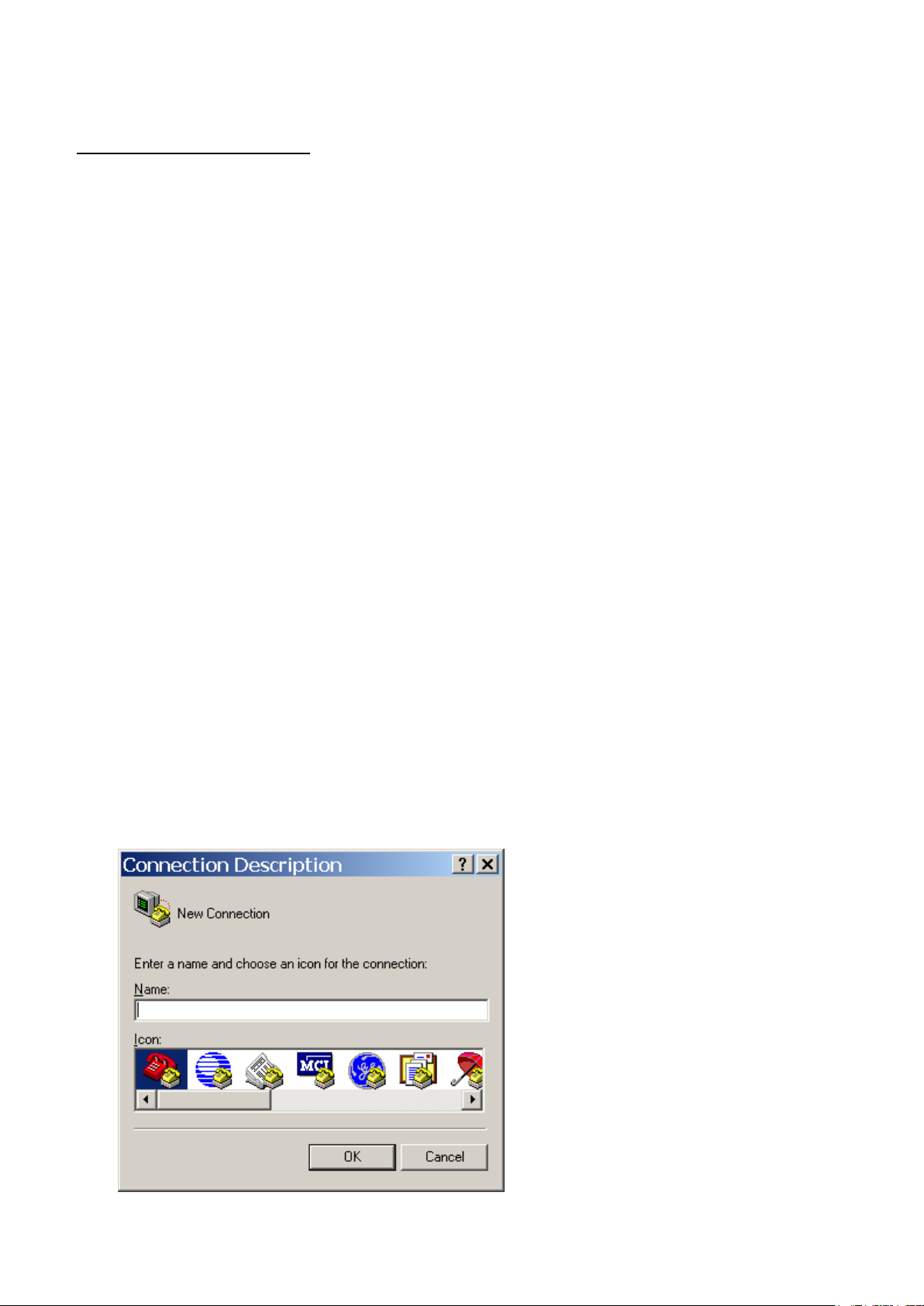
You will then be presented with the following screen: -
©2015 EMS Security Group Ltd. All rights reserved. TSD248 Iss 2 25/06/15 AJM
Page 8
EMS SYSTEM 7000
8
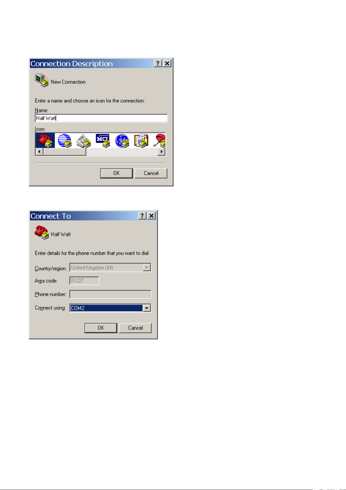
Now enter your desired connection description: -
Then click on the ‘OK’ button, and the screen will change to the following: -
©2015 EMS Security Group Ltd. All rights reserved. TSD248 Iss 2 25/06/15 AJM
Page 9
EMS SYSTEM 7000
9
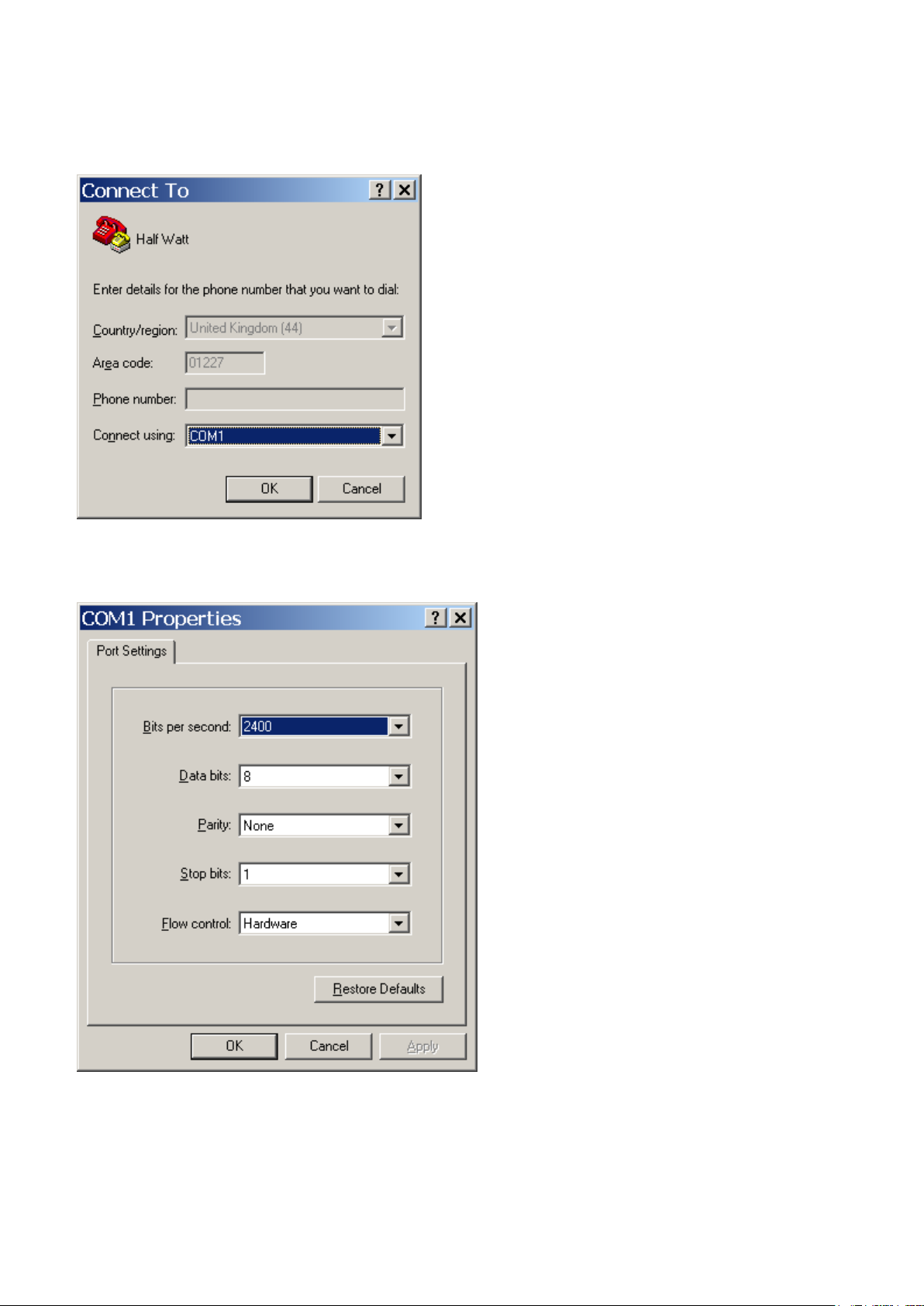
Now select the Comm Port required as below: -
Then click on the ‘OK’ button, and the screen will change to the following screen:
©2015 EMS Security Group Ltd. All rights reserved. TSD248 Iss 2 25/06/15 AJM
Page 10

EMS SYSTEM 7000
10
Now select the following settings: -
Once completed, click on the ‘Apply’ button and then the ‘OK’ button. The screen will
change to display:-
©2015 EMS Security Group Ltd. All rights reserved. TSD248 Iss 2 25/06/15 AJM
Page 11

EMS SYSTEM 7000
11
Now select ‘Call’ and ‘Disconnect and the screen will change to display: -
©2015 EMS Security Group Ltd. All rights reserved. TSD248 Iss 2 25/06/15 AJM
Page 12

EMS SYSTEM 7000
12
Now select ‘File’ and ‘Properties’. The screen will change to display:-
Now select the ‘Settings’ tab and the screen will change as below: -
©2015 EMS Security Group Ltd. All rights reserved. TSD248 Iss 2 25/06/15 AJM
Page 13

EMS SYSTEM 7000
13
The Settings should be set as follows: -
Once the settings are as above, click on the ‘ASCII Setup‘ button and check that the
settings are as follows: -
©2015 EMS Security Group Ltd. All rights reserved. TSD248 Iss 2 25/06/15 AJM
Page 14

EMS SYSTEM 7000
14
Once the settings are as above, click on the ‘OK’ button then on the next window click on
the ‘OK’. We can now establish a connection by selecting ‘Call’ and ‘Call’ as below: -
Once completed, HyperTerminal is configured.
Please Note: To prevent future reconfiguration, the HyperTerminal session can
be saved for future use.
©2015 EMS Security Group Ltd. All rights reserved. TSD248 Iss 2 25/06/15 AJM
Page 15

EMS SYSTEM 7000
15
6. ID
6.1 Each of the transmitters inputs have their individual identification numbers set from
this menu. This allows the input to be added into the IRIS receiver with a unique
number. The identification numbers are defaulted to range from A0001 - A0008 for
inputs 1-8. Under normal circumstances this menu should not require changing.
6.2 The only time the default settings will require changing is if additional transmitter
units have been added to an existing installation. If this is the case a print out
should be taken from the IRIS Receiver and the transmitter ID settings checked.
The new transmitter can then be added to the system ensuring that the new inputs
id’s do NOT correspond with any already programmed into the IRIS unit.
6.3 To change the inputs identification number, from the command menu type id and
press the enter key. The display will then show:
Input No: 1
ID code (hex) is A0001
Change Y/N?
To change the ID press Y and then the enter key, the display will now show:
New ID Code (hex)
Enter the new ID code and press enter. If the hex number is a valid number the
display will change to show:
New ID Code (hex) NNNNN (Where N represents new code)
NNNNN
Input No: 2
ID code (hex) is
Change Y/N?
Repeat for all inputs if changes are required. If all changes are complete press the
enter key until the display returns to:
COMMAND id, con, type, mode
Txd, quit >
7. CON
7.1 Each of the transmitters inputs can be programmed to operate via a normally open
connection or normally closed configuration. The default setting for all of the inputs
is to normally open. If this requires changing, from the command menu type con
and press the enter key. The display will then show:
Input Number 1 is N/O
Change Y/N
©2015 EMS Security Group Ltd. All rights reserved. TSD248 Iss 2 25/06/15 AJM
Page 16

EMS SYSTEM 7000
16
8. TYPE
7.1 Each of the transmitters inputs have a type setting, which sets the kind of alarm
data that is transmitted to the Iris Receiver. The setting is defaulted to alarm for
each of the inputs, but can be changed to one of the following depending on the
overall systems requirements:-
8.2 NU = NOT USED: - If selected no output transmission will be generated when
triggered and no call in’s signals from the input will be transmitted.
8.3 RESET: - If selected on triggering this input the IRIS receiver will be remotely reset.
To ensure correct operation this input requires it’s mode setting programmed to
hand push, it must also be added into the IRIS receiver as an Interrogator hand
push and the IRIS requires 7202 Interrogator software installed.
8.4 LOW BATTERY: - If selected on triggering this input a low battery alarm
transmission will be sent to the IRIS receiver. To ensure correct operation this input
requires it’s mode setting programmed to hand push and should be added into the
IRIS as an opposed action hand push. It should be noted that the first transmission
from a low battery input will not be seen but every subsequent transmission from
the input will be registered on the IRIS.
8.5 TAMPER: - If selected on triggering this input a tamper alarm transmission will be
sent to the IRIS receiver. To ensure correct operation this input requires it’s mode
setting programmed to hand push and should be added into the IRIS as an opposed
action hand push.
8.6 LOCAL: - If selected on triggering this input a local alarm transmission will be sent
to the IRIS receiver. This input can have it’s mode setting set to either hand push
or contact and can be added into the IRIS as an opposed action hand push or N/O
contact operated transmitter. If the mode is set to contact the input should be
added into the IRIS as a Local N/O contact, this will then send input restored data
when the input goes clear. If the input is not clear when the IRIS receiver is reset,
a message will be displayed on the IRIS telling you that the input has not reset. If
the mode is set to hand push the input should be added into the IRIS receiver as an
opposed action hand push, this does not transmit input restored data as explained
above.
8.7 ALARM: - If selected on triggering this input a full alarm transmission will be sent
to the IRIS receiver. This input can have it’s mode setting set to either hand push
or contact and can be added into the IRIS as an opposed action hand push or N/O
contact operated transmitter. If the mode is set to contact the input should be
added into the IRIS as an Alarm N/O contact, this will then send input restored data
when the input goes clear. If the input is not clear when the IRIS receiver is reset,
a message will be displayed on the IRIS telling you that the input has not reset. If
the mode is set to hand push the input should be added into the IRIS receiver as an
opposed action hand push, this does not transmit input restored data as explained
above.
©2015 EMS Security Group Ltd. All rights reserved. TSD248 Iss 2 25/06/15 AJM
Page 17

EMS SYSTEM 7000
17
8.8 If the type requires changing, from the command menu type type and press the
enter key. The display will then show:-
Input Number 1 is Alarm
Change Y/N ?
To change press Y and then enter. The display will then change to the following:
Enter new type 0 = NU, 1 = RESET
2 = LOWBAT, 3 = TAMPER, 4 = LOCAL, 5 = ALARM
Enter the required number and press enter. The display will now show:
Input Number 1 is NNNNNN ( Where N is the new option chosen)
Input Number 2 is Alarm
Change Y/N ?
If you don’t require the input to be changed press N or Enter. The display will then
change to show the next input.
This continues until all 8 contacts are looked at. On answering Y/N to contact 8 the
display will change to show the command menu. To check settings type type to reenter menu.
9. MODE
9.1 Each of the transmitters inputs have a mode setting, which sets the operation of
the input. The unit has two modes contact and hand push. The default for all inputs
is set to contact.
9.2 If contact is selected the input should be added into the IRIS receiver as a N/0
contact operated transmitter, this will then cause the input to transmit data on both
an activation of the input and the reinstating of the input. This will be shown on the
IRIS when its being reset, as it will show which inputs have not transmitted their
restored signals by showing that the input is not reset. This contact setting is only
recommended when the alarm type is set to either a local or alarm transmission.
9.3 If hand push is selected the input should be added into the IRIS receiver as an
opposed action hand push transmitter, this will then cause the input to transmit
data on an activation of the input. This setting can be selected for all alarm types
and is imperative for the correct activation of alarm types low battery, tamper and
reset.
9.4 If the mode requires changing, from the command menu type mode and press the
enter key. The display will then show:
Input Number 1 is CONTACT
Change to HANDPUSH Y/N ?
©2015 EMS Security Group Ltd. All rights reserved. TSD248 Iss 2 25/06/15 AJM
Page 18

EMS SYSTEM 7000
18
To change press Y and then enter. The display will then change to the following:
Input Number 1 is HANDPUSH
Input Number 2 is CONTACT
Change to HANDPUSH Y/N ?
If the input does not require to be changed press N or Enter. The display will then
change to show the next input.
This continues until all 8 contacts are looked at. On answering Y/N to contact 8 the
display will change to show the command menu. To check settings type mode to
re-enter menu.
10. TXD
9.1 The txd function when entered causes each of the inputs being used to transmit
three bursts of call in data. To enter this function type txd from the command
menu and press the enter key. The display will then show,
Transmit Call Ins
Call in 08EA0000
Call in 08EA0000
Call in 08EA0000
Call in 08EA0001 }
Call in 08EA0001 } This is call in data for input 1
Call in 08EA0001 }
This is then repeated for all active inputs showing each of the inputs ID’s in three
transmitting bursts. Once completed it will carry on repeating the above sequence.
To exit this function press the enter key 3 times.
11. QUIT
11.1 To update any information changed and exit the programming mode quit must be
typed followed by pressing the enter key. The program mode is then exited. The
display will then show any transmissions from the transmitter in the following
format:
Transmitting Data: (hex transmission and ID code shown)
©2015 EMS Security Group Ltd. All rights reserved. TSD248 Iss 2 25/06/15 AJM
Page 19

EMS SYSTEM 7000
19
12. LOAD DEFAULT VALUES
12.1 This command is not actually shown on the menu but can be used to default all of
the systems inputs. Default values for the inputs are as follows:
Inputs 1-8.............. ID A0001-A0008
Con Normally Open
Type Alarm
Mode Contact
12.2 To change all of the inputs to their default settings type load defaults and press
the enter key. The display will now show:
Load Default Values Y/N ?
Press the Y key and then enter the display will then change to show:
Please Wait.....
The system will then return to the command menu.
©2015 EMS Security Group Ltd. All rights reserved. TSD248 Iss 2 25/06/15 AJM
Page 20

EMS SYSTEM 7000
20
13. Internal Input Wiring
Connection Drawing
Figure 4
©2015 EMS Security Group Ltd. All rights reserved. TSD248 Iss 2 25/06/15 AJM
Page 21

EMS SYSTEM 7000
21
14.1
With the control keyswitch in the
“CLEAR” position the screen
should now display:
System Clear
01/10/93 13:26
14.2
Turn the control keyswitch to the
“RESET” position. The screen
should now display:
*** SYSTEM RESET ***
13:26
14.3
Press the “0” key, and the screen
will now display:
Enter Your PIN
For Menus > _
=Done =Del 13:26
14.4
Enter the engineering default
PIN: “221100” and then press
the “” button, the screen will
now display:
| ** Main Menu **|
>Pins & Access <
| System Support |
2=Help 13:27
14.5
Press the “” button until screen
displays:
| Time and Date |
> Radio Setup <
| Output Setup |
2 = Help 16: 37
14.6
Press the “1” button and the
screen will display:
| ** Radio Setup ** |
> Add Transmitter <
| Txer Details |
2 = Help 16:37
14.7
Press the “1” button and the
screen will display:
| -Add Transmitter-|
> Add Hand push <
| Add Moneyclip |
2 = Help 16:37
14.8
Press the “” or “” buttons to
highlight the type of transmitter
to be added, and press the “1”
button and the screen will change
to display the options available:
| - Hand push Type - |
> Opposed Action <
| Non-Opposed |
2 = Help 16:37
14.9
With the opposed action between
the > and < arrows, press the
“1” button and the screen will
change to display:
Operate Transmitter
NOW or press
Escape to cancel
16:38
14. Adding An Input (Hand push Mode) Into The IRIS Radio Receiver
The following sequence of operations is required when adding an input with the mode
setting programmed as hand push into the UHF IRIS Radio Receiver.
©2015 EMS Security Group Ltd. All rights reserved. TSD248 Iss 2 25/06/15 AJM
Page 22

EMS SYSTEM 7000
22
14.10
Activate the required input to be
added by applying or removing
voltage (depending upon N/O or
N/C input) and the screen will
display:
Release all buttons
NOW
16:38
14.11
After a short period of time the
screen will change to display:
Operate Transmitter
Again or press
Escape to cancel
16:38
14.12
Using the same operation, once
again generate a transmission,
after a short period of time the
screen will change to display:
Hand Push 001
Added
Push any key
16:38
14.13 You may now add additional inputs by repeating the actions detailed. If no further
inputs are to be added then escape from this menu by pressing the 3 button on
the keypad or returning the control keyswitch to the CLEAR position.
©2015 EMS Security Group Ltd. All rights reserved. TSD248 Iss 2 25/06/15 AJM
Page 23

EMS SYSTEM 7000
23
15.1
With the control keyswitch in the
“CLEAR” position the screen should
now display:
System Clear
01/10/93 13:26
15.2
Turn the control keyswitch to
“RESET”. The screen should now
display:
*** SYSTEM RESET ***
13:26
15.3
Press the “0” button, and the screen
will now display:
Enter Your PIN
For Menus > _
=Done =Del 13:26
15.4
Enter the engineering default PIN:
“221100”, then press the “”
button, and the screen will display:
|** Main Menu ** |
> Pins & Access <
| System Support |
2=Help 13:27
15.5
Press the “” button until the
screen displays:
| Time and Date |
>Radio Setup <
| Output Setup |
2 = Help 16: 37
15.6
Press the “1” button and the screen
will display:
| ** Radio Setup ** |
> Add Transmitter <
| Txer Details |
2 = Help 16:37
15.7
Press the “1” button and the screen
will display:
| -Add Transmitter-|
> Add Hand push <
| Add Moneyclip |
2 = Help 16:37
15.8
Press the “” button until the
screen displays:
| Add Foot - Trip |
> Add Contact Txer <
| Add Interrogator |
2 = Help 16:37
15.9
Press the “1” button and the
screen will display:
| -- Contact Type -- |
> Alarm N/O <
| Alarm N/C |
2 = Help 16:37
15. Adding An Input (Contact Mode) Into The IRIS Radio Receiver
The following sequence of operations is required when adding an input with the mode
setting programmed as contact into the UHF IRIS Radio Receiver.
©2015 EMS Security Group Ltd. All rights reserved. TSD248 Iss 2 25/06/15 AJM
Page 24

EMS SYSTEM 7000
24
15.10
Select Alarm N/O or Local N/O by
using the “” and “” buttons and
when the required setting is
between the > and < arrows press
the “1” button and observe the
display changes to:
Operate Transmitter
NOW or press
Escape to cancel
16:38
15.11
Activate the required input to be
added by applying or removing
voltage (depending upon N/O or
N/C input) and the screen will
display:
Reset Transmitter
NOW
16:38
15.12
After a short period of time the
screen will change to display:
Operate Transmitter
Again or press
Escape to cancel
16:38
15.13
Using the same operation, once
again generate a transmission,
after a short period of time the
screen will change to display:
Contact 001
Added
Push any key
16:38
15.14 You may now add additional inputs by repeating the actions detailed. If no further
inputs are to be added then escape from this menu by pressing the “3” button on
the keypad or returning the control keyswitch to the “CLEAR” position.
©2015 EMS Security Group Ltd. All rights reserved. TSD248 Iss 2 25/06/15 AJM
Page 25

EMS SYSTEM 7000
25
16.1
With the control keyswitch in
the “CLEAR” position the screen
should now display:
System Clear
01/10/93 13:26
16.2
Turn the control keyswitch to
the “RESET” position. The
screen will now display:
*** SYSTEM RESET ***
13:26
16.3
Press the “0” key, and the
screen will display:
Enter Your PIN
For Menus > _
=Done =Del 13:26
16.4
Enter the engineering default
PIN: “221100” and press the
“” button, and the screen will
now display:
|** Main Menu **|
> Pins & Access <
| System Support |
2=Help 13:27
16.5
Press the “” button until the
screen displays:
| Time and Date |
> Radio Setup <
| Output Setup |
2 = Help 16: 37
16.6
Press the “1” button and the
screen will display:
| ** Radio Setup ** |
> Add Transmitter <
| Txer Details |
2 = Help 16:37
16.7
Press the “1” button and the
screen will display:
| -Add Transmitter-|
> Add Hand push <
| Add Moneyclip |
2 = Help 16:37
16.8
Press the “” button until the
screen displays:
| Add Contact Txer |
> Add Interrogator <
| Add P-Call Txer |
2 = Help 16:37
16. Adding A Reset Input (Hand push Mode) Into The IRIS Radio
Receiver
The following sequence of operations is required when adding an input, which is required
to reset the IRIS receiver. The inputs mode setting must be programmed as a hand push
and the input must be programmed into the UHF IRIS Radio Receiver as an Interrogator
transmitter. It should be noted that the IRIS receiver must have installed 7202
Interrogator software for this function to operate.
©2015 EMS Security Group Ltd. All rights reserved. TSD248 Iss 2 25/06/15 AJM
Page 26

EMS SYSTEM 7000
26
16.9
Press the “1” button and the
screen will display:
Operate Transmitter
NOW or press
Escape to cancel
16:38
16.10
Activate the required input to be
added by applying or removing
voltage (depending upon N/O or
N/C input) and the screen will
display:
Release all buttons
NOW
16:38
16.11
After a short period of time the
screen will change to display:
Operate Transmitter
Again or press
Escape to cancel
16:38
16.12
Using the same operation, once
again generate a transmission,
after a short period of time the
screen will change to display:
Interrogator 001
Added
Push any key 16:38
16.13 You may now add additional inputs by repeating the actions detailed. If no further
inputs are to be added then escape from this menu by pressing the 3 (three) on
the keypad or returning the key to the “CLEAR” position.
©2015 EMS Security Group Ltd. All rights reserved. TSD248 Iss 2 25/06/15 AJM
Page 27

EMS SYSTEM 7000
27
17.2
Press the “” button until the
screen displays:
| Time and Date |
> Radio Setup <
| Output Setup |
2=Help 16: 37
17.3
Press the “1” button and the
screen will display:
| ** Radio Setup ** |
> Add Transmitter <
| Txer Details |
2=Help 16:37
17.4
Press the “” button and the
screen will display:
| Add Transmitter |
> Txer Details <
| Set Radio Rules |
2=Help 16:37
17.5
Press the “1” button and the
screen will display:
| - Txer Details - |
> Name by Number <
| Name by Tx |
2=Help 16:37
17.6
Press the “” button and the
screen will display:
| Name by Number |
> Name by Tx <
| View Names |
2=Help 16:37
17.7
Press the “1” button and the
screen will display:
Operate Transmitter
NOW or press
Escape to cancel
16:38
17.8
Generate a transmission by
activating the input that
requires re-texting and the
screen will display:
Release all buttons
NOW
16:38
17.9
After a short period of time the
screen will display:
Operate Transmitter
Again or press
Escape to cancel
16:38
17.10
Once again generate a
transmission from the same
input, the screen will change to
display:
The current selected character
is shown above the centre bar.
| |
| |
4<HIJKL M NOPQR>6
2= Help | 16:38
17. Assigning Text Description For An Input
17.1 Repeat steps 16.1 to 16.4.
©2015 EMS Security Group Ltd. All rights reserved. TSD248 Iss 2 25/06/15 AJM
Page 28

EMS SYSTEM 7000
28
KEY
FUNCTION
0
Enters a blank space into the new device name being entered.
3
Exits to the previous menu
4
Moves the alphabet wheel of characters to the Left, by one character space at a
time.
5
Enters the character in the centre directly above the character selector |.
6
Moves the alphabet wheel of characters to the Right, by one character space at a
time.
7
Moves the flashing cursor to the left, through the new device name by one
character space at a time.
8
Moves the alphabet wheel of characters to the Right, by 12 character Spaces at a
time.
9
Moves the flashing cursor to the Right, through the new device name by one
character space at a time.
Backspace Key, Deletes by one character. (Deletes to the left only)
Saves and completes the current activity and returns the program to the
appropriate display.
17.11 By using the “4” button to move left or the “6” button to move right, move to the
letter or number required and press the “5” button to select the character.
17.12 Repeat 16.11 until all letters have been selected. Once completed, Press the “”
button to save the information.
17.13 Once completed you may now escape from this menu by pressing the “3” button
on the keypad until the “SYSTEM RESET” message appears or by returning the
control keyswitch to the “CLEAR” position.
©2015 EMS Security Group Ltd. All rights reserved. TSD248 Iss 2 25/06/15 AJM
 Loading...