

Page 1
EMS iVu9s+
Video Wall Controller
User Manual
Page 2

Catalog
Overview …………………………………………………..….…3
Specification ……………………………………………….……3
Features ………………………………………………….….....4
OSD Menu……….………………………………………...…...5
Remote controller ……………………………………….…..…6
Front Panel (buttons) ...........................................................6
Packaging ..............................................................................7
About Us ................................................................................7
2
Page 3

Legal Notice and Disclaimer
Thank you for choosing EMS products! This user manual provides a description of the
iVu9s+ Video Wall Controller’s hardware and relevant guidelines for key functions.
Please read this document carefully and adhere to its instructions.
This manual provides the description of all the functions of the iVu9s+ Video Wall
Controller. The product you purchased may not support certain functions dedicated to
specific models.
Legal Notice
All features, functionality, and other product specifications are subject to change without
prior notice or obligation.
Information presented is subject to change without notice.
No part of this publication may be reproduced, stored in a retrieval system, or
transmitted, in any form or by any means, mechanical, electronic, photocopying,
recording, or otherwise, without prior written permission of EMS Systems, Inc..
EMS and the EMS logo are registered trademarks of EMS Systems, Inc.. Other
products and company names mentioned herein may be the trademarks of
their respective companies.
Disclaimer
In no event shall Electronic Modular Solutions Ltd (EMS) liability exceed the price paid
for the product from direct, indirect, special, incidental, or consequential damages
resulting from the use of the product, its accompanying software, or its
documentation. EMS makes no warranty or representation, expressed, implied, or
statutory, with respect to its products or the contents or use of this documentation and
all accompanying software, and specifically disclaims its quality, performance,
merchantability, or fitness for any particular purpose. EMS reserves the right to revise
or update its products, software, or documentation without obligation to notify any
individual or entity.
3
Page 4

Safety Warnings
1. The iVu9s+ video wall controller can operate normally in a temperature
between 0ºC–40ºC and in a relative humidity of 0%–95%. Please ensure the
operating environment is well-ventilated.
2. The power supply provides 12V/3A and devices connected to the iVu9s+ video wall
controller must provide a correct supply voltage (100–240V).
3. Do not place the iVu9s+ video wall controller in direct sunlight or near chemicals.
4. Unplug the power cord and all connected cables before cleaning. To clean the
iVu9s+ video wall controller, wipe it with a dry towel. Do not use chemicals or
aerosols to clean the iVu9s+ video wall controller.
5. Do not cover or place any objects on the iVu9s+ video wall controller to ensure
normal operation and to avoid overheating.
6. Do not place the iVu9s+ video wall controller near any liquid.
7. Do not place the iVu9s+ video wall controller on an uneven surface to avoid it
falling..
8. Make sure the voltage is correct in the location where the iVu9s+ video wall
controller is installed. Contact the distributor or the local power supply company for
more information.
9. Do not place any object on the power cord.
10. Under no circumstances should you attempt to repair the iVu9s+ video wall
controller. Improper disassembly of the product may expose the users to electric
shock and other risks. For any enquiries regarding repairing the iVu9s+ video wall
controller, please contact your distributor.
11. iVu9s+ video wall controllers should only be installed in server rooms and
maintained by authorized server managers or IT administrators. The server room
should be secured and only accessible by authorized staff members.
Warning:
There is the possibility of an explosion if the battery is replaced incorrectly. Replace
only with the same or equivalent type recommended by the manufacturer. Dispose of
used batteries according to the manufacturer’s instructions.
DO NOT touch the system fan as it may cause injury and hardware failure.
4
Page 5

Overview
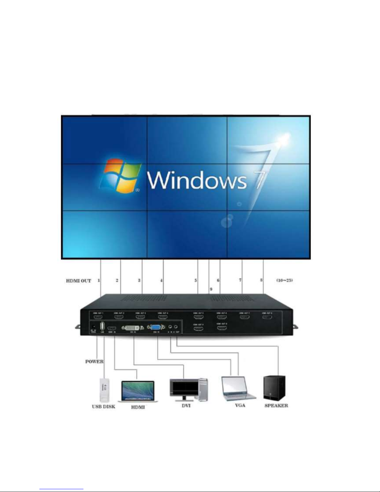
The video wall controller is a plug and play processor, able to process and split the
signal input, and distribute various formats of signal to multiple terminal displays,
including LCD TV, monitor, DID, DLP, Plasma, etc..
It supports many types of input sources, HDMI, DVI, VGA, Composite video,
video/audio/photo by USB stick. Each video with audio can be switched
together. Output HDMI interface, supports resolution up to 1920x1080. The
video wall controller operates by remote control, buttons and an RS232 serial
port.
Benefits
The benefits of the iVu9s+ include:
Accurate, high-definition image quality
Silent operation
HDCP support
Simple setup
Cost-saving implementation of a large display
Major power saving compared to PC-based implementation
Space saving
Features
The features of the iVu9s+ include:
One HDMI input
Nine HDMI outputs
Supports up to 1920 x 1080 output resolution per monitor
Supports multiple display modes, including clone mode (1 x 1) and full mode (2 x 2, 2 x
3, 3 x 2, 4x2, 2x4, 3 x 3 .. plus more)
HDCP support for compliance with Blu-ray Disc players and video game consoles
Bezel compensation technology for compensating for gaps between monitors
Plug-and-Play
Multi input sources supported, Composite video, VGA, DVI, HDMI, USB driver
Supports 180° rotation each screen.
Easy operation with buttons and a remote controller.
DCP compliant: HDMI 1.3, HDCP protection
RS232 for firmware upgrade and system integration
3.5mm audio out to support analog sound systems
Easy maintenance and silent operation
Page 6
Hardware Specifications
Caution: Modifying the hardware, software, or firmware of the EMS products will
void the warranty. EMS is not responsible for any form of damage or loss of data caused
by modding EMS products. Users will be solely responsible for the risks of possible data
loss and system instabilities caused by modifying hardware, altering the default system
firmware or installing unauthorized third-party applications on EMS products.
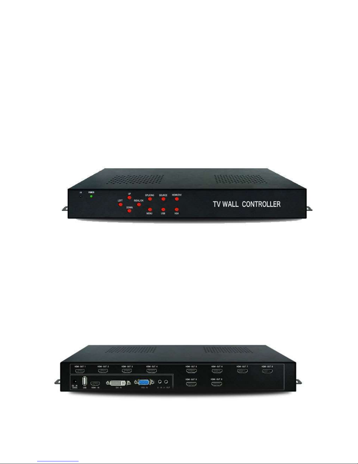
iVu9s+ Front Panel
The front panel has the following buttons and indicators:
One power LED indicator
Ten OSD buttons
One Infrared sensor
iVu9s+Rear Panel
The rear panel has the following connectors and switches:
One -> HDMI, VGA, DVI, Composite input
One USB input
Ten HDMI outputs
One power input
One RS232
Page 7

Dimension
Dimensions (unit: mm)
Remote control
1. Remote control function:
Remote control operation via the mosaic screen, just like operating a TV, easy & simple.
2. remote control buttons function diagram:
Page 8

IR receiver - Power LED Front Panel same as Remote Choose inputs/outputs/screens
Page 9

Technical Specifications
Item Specification
HDMI input
Interface
HDMI( support HDCP1.3 and DVI1.0)
Resolution Up to 1920*1080@60Hz
Color 24bit,16.77M
DVI input
Interface
DVI( support DVI1.0)
Resolution Up to 1920*1080@60Hz
Color 24bit,16.77M
VGA input
Interface DB15
Resolution 800*600 to 1920*1080@60Hz
AV input
Interface RCA
Identification Auto
Standard PAL,NTSC
USB
Video RM, RMVB, AVI, WMV, MOV, MP4, FLV, MPG,
DAT, MPEG and so on, with resolution up to
1080P
Audio MP3, WMA, FLAC and so on
Picture JPG, BMP, PNG
Text TXT
Audio in Fit for VGA video
Audio output Fit for output video
HDMI output 1024*768@60hz,720P@60Hz,1080P@60Hz
Controller Remote, button key, RS232 serial port
Power
Input: DC 12V3A
Dimension 350mm(L)x200mm(W)x70mm(H)
Weight 3.0KG
Page 10

Getting Started
Installation Steps
To install the iVu9s+, please follow the installation steps below.
1. Install the display devices.
2. Mount the iVu9s+ (optional).
3. Connect HDMI cables for video input and output, RS232 cable (optional), and
power adapter to the iVu9s+.
4. Adjust the output resolution. See Input and Output Resolution for more
information.
5. Select a display mode. See Display Mode for more information.
6. Adjust the iVu9s+ bezel compensation setting to align the images (optional).
Install Display Devices
The display devices (LCD monitors, TVs) are installed in a rectangular arrangement
by following your chosen display mode.
Recommended installation procedures are:
Use identical display devices
Keep the gaps between panels as small as possible
Keep all horizontal gaps between monitors in the array consistent
Keep all vertical gaps between monitors in the array consistent
Mounting
The iVu9s+ must be placed on a table, desk or any other firm surface. The iVu9s can
also be mounted using the included mounting brackets. The installation location must be:
Out of direct sunlight
Without anything on top of it
On a firm surface
Away from moisture and liquids
Connect Cables
The cables that need to be attached are listed below
HDMI input cable – from the video source (PC, console, player, etc) to the iVu9s.
HDMI output cables – from the iVu9s+ to the LCD panels or other video box controllers.
Make sure the cables are connected to the correct monitors
Power cable – from the power adapter.
Video Wall Array(3x3)
1 2 3
4 5 6
7 8 9
Connect the Video Source to the iVu9s+
The video source directly connects to the iVu9s+ through an HDMI cable. To connect the
video source to the iVu9s+, follow these steps:
Page 11

1. Attach the HDMI video cable to the HDMI output of the video source.
2. Attach the HDMI video cable to the HDMI input on the iVu9s+.
Connect iVu9s+ and the Display Devices
The iVu9s+ directly connects to the display devices through HDMI cables. To connect the
iVu9s+ to the display devices, follow these steps:
1. Attach the HDMI video cables to the HDMI output of the iVu9s+.
2. Attach the HDMI video cables to the HDMI input on the display devices.
Connect the Power Adapter to iVu9s+
Connect the included power adapter to the iVu9s+.
The iVu9s+ supports 1x USB, 1x HDMI, 1x VGA, 1x AV input, all inputs are embedded or
bound to the audio input, user can access all the signals, the input interface as below:
USB interface: A USB storage device can be directly inserted into the USB slot, you can play
video, pictures, TXT documents or MP3 files within USB disk ;
HDMI interface: can be connected to the computer, DVD players and other HDMI output
device with embedded audio;
VGA interface: a device that can be connected to a computer or other device with a VGA &
Audio-IN , the audio will be syncronised to the VGA;
AV Video interface: AV-video signal, R and L are respectively connected with the left and
right channel, icluding the audio signal of video binding;
Audio connection
A-OUT for the audio output of the machine, it can connect with speaker or others audio
devices.
Power on
Once all the cables are connected, only then insert the AC power supply, turn on the
power switch, the power indicator light will become green - the device is working.
Parameter setting
Complete splicing device installation and connection, open the switch will appear or display a
black screen image signal. If black signal, need by remote control or button to switch to the
corresponding signal source, such as: then the HDMI signal and ua1 switch directly to the
HDMI signal source.
After the image is out, it is possible that some of the LCD screen image is inverted, or when
the film because of the LCD screen frame caused by image distortion and other issues, this
time we also need to set up the parameters of the mosaic through the menu keys (MENU),
so we need to be familiar with the operation of the menu.
Press the MENU key, then press the left button to press the left button to come out a few
different
Page 12

Menu 1, 3, 4 categories of the factory settings has been set at the best recognized state,
user does not need to change these, we need only to set menu 2:
1. OSD Language
Move the cursor to OSD Language, press left or right, then user can choose OSD language.
2. Restore Factory default
Usually do not need to reset this, however if the user settings are messed up, you can try to
use the reset factory settings.
3. Mosaic (splicing) on
Move the cursor to the Mosaic, press left or right to choose open mosaic or off, same as the
remote controll button.
4. Mosaic (splicing) config 3x3
Press left or right choose different mosaic modes, like 1X2,1X3,1X4,2X1,2X2,3X1,4X1, 2x3,
3x2, 4x2, 2x4, 3x3, example 1X2 mode, this will mean across 1 and down 2 rows.
5. Mosaic (splicing) mac address 1
The mac address is the machine output interface, if this display unit connects to the HDMI1
interface, the user movex the cursor to the mosaic mac address and presses it left or right,
this display unit will display mosaic mac address:1
6. Soft Address setting 1
This address can be changed, change the one display unit soft address, the display unit will
display different video. Such as 2*2 mode:
Page 13

Mirror
This function enables the screen rotation of 180 degrees, due to a lot of LCD TV’s having a
thicker bezel at the bottom, then the video can be rotated by 180 degree likewise the screen
would be flipped vertically (upside down), through the mirror function the screens can be
individually set to rotated 180 degrees. First set the cursor to the mac address of the
corresponding screen, and then put the cursor to the mirror, and press the left or right to
the rotate the screen will be in real-time.
Horizontal 0 and Vertical mosaic pitch 0
When using displays with noticeable bezels, Bezel Compensation can be used for greater
image alignment.
The horizontal & vertical pitch can be used to adjust for the size of the screen bezel width,
this will keep images without distortion, as shown below:
Page 14

Output mode
Can be set to 1080P60, 720P60, 1024x768@60 three resolution outputs to adapt to different
display devices. You can press “7” on the remote to select different resolutions.
Output Type
Can be set HDMI or DVI model. if you set HDMI model, the HDMI port will output audio;
if you set DVI model, the HDMI port will not output audio. But A-out is analog audio output
port, no matter if you select HDMI or DVI model, it will have audio output. If your monitor
only supports DVI model, then you must choose DVI output, if your monitor only supports
HDMI model, you must choose HDMI output. you can press “9” on the remote to choose
DVI or HDMI output model.
USB function
This video wall controller can decode video, audio, picture, TXT file of the USB disk
Video decoding list as follow:
Audio: decoding MP3 and other formats audio files.
Photo: decoding JPG and others.
TXT: decoding , TXT file.
play all the video or need to play the picture, TXT document, MP3 content, you can press
the remote control to return the keys and then re enter the play folder, press the play /
pause button to play all of the content, or through the navigation keys to select some of the
contents of the OK.
Normal playback state according to the remote OK key can be transferred out of the fast
forward, slow progress, a song, a song pause or image playback mode.
Page 15

Display Modes
** Example display modes
Page 16

PACKAGING
Page 17

Package Included
1 x Main Unit.3x3 Video Wall Controller
1x Remote Controller
1x Power Adapter
1x User Manual
Dimensions of the package: 36cm x 21cm x 7cm (14.17in x 8.27in x 2.76in)
Package weight: 3.5kg (7.72lb.)
ABOUT US
Electronic Modular Solutions offers the best devices to support the visualization and imaging needs of a diverse
market. Our products are not just cost-effective, but most of all, also very user-friendly as we strive to support
every industry's productivity and efficiency.
Support
Do not hesitate to contact us for support and after-sales service. Our experienced and expert team is ready to be
of assistance to any problem you encounter in operating and installing our products. Expect professional advice
with the highest level of customer support. We are willing to work with you in answering your queries and
providing solutions to your problems, contact support@ems-imaging.com.
Electronic Modular Solutions Ltd.
www.ems-imaging.com
Tel (International): +44 116 3500110
Local (U.K) 0116 3500110
 Loading...