

Page 1
©2018 EMS Ltd. All rights reserved. MK192 Iss9 08/05/2018 AJM
1 2 3
4 5 6
7 8 9
0
MENU
SELECT
HELP
MENU
ESCAPE
CHARACTER
LEFT
CHARACTER
ENTER
CHARACTER
RIGHT
CURSOR
LEFT
CHARACTER
TEN RIGHT
CURSOR
RIGHT
MENU DOWN
/ DELETE
PIN ACCESS /
SPACE
MENU
UP / DONE
1 2 3
4
5 6
7 8 9
0
Universe
+
Range
CLEAR
RESET
TEST
Page 2

Page 3

Contents
Menu structure 4-5
Introduction 6
Tools & test equipment 6
Accessing the engineering menus 7
Receiver and transmitter location 7
Checking background interference levels 8
How to reduce interference 9
Monitoring transmitter signals 9
Installation 10-12
Iris+ back box connections explained 13-14
Post installation testing 15
Operating instructions 16
Adding a transmitter 17
Naming a transmitter 18-19
Deleting a transmitter 20
Add a new user 21-22
Transmitter grouping 23-24
Relay output conguration 25-26
Example relay wiring 27
Helpful hints 28
Glossary 29
Appendix 29
Technical specications 30
Page 3 of 32
Page 4
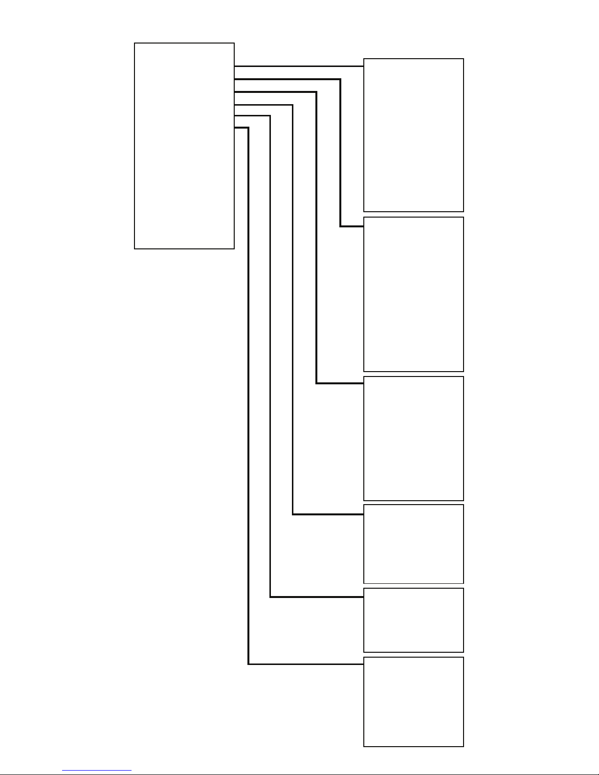
*Main Menu*
PINs & Access
System Support
Serial Comms
Pager Setup
Engineer Ctrl
Time & Date
Radio Setup
Output Setup
Logging
Relay Setup
Remote Rxers
Direct Inputs
Network
Txer Grouping
Bus I/O
*Pins & Access*
User Log On
View User
Change PIN
Add 6 Digit User
Add 4 Digit User
Edit User
Delete User
Access & Buzzer
Front Screen Text
Site Address Text
Delete All Users
*System Congure*
Software Versions
Print One Setup
Print All Setup
Test Printer
Printer Device
CR Translation
Export One Setup
Export All Setups
Import Setup
Imp/Exp Device
Memory Stats
*Serial Comms*
Device Table
Re-start Bus
Re-online Device
Bus Master Setup
Pager232 Redir’
Aux232 Redirect
Printer Redirect
Monitor Comms
Delete Device
*Pager Setup*
Add Pager
Delete Pager
View Pagers
Transmitter Setup
Test Pagers
Menu structure (part 1)
Page 4 of 32
*Engineers Ctrl*
Engineers Port
Warm Start
Cold Start
Erase EEPROM
*Date/Time*
Set The Time
View The Date
Set The Date
View BST/GMT
Set BST/GMT
Day-Night Ctrl
Page 5
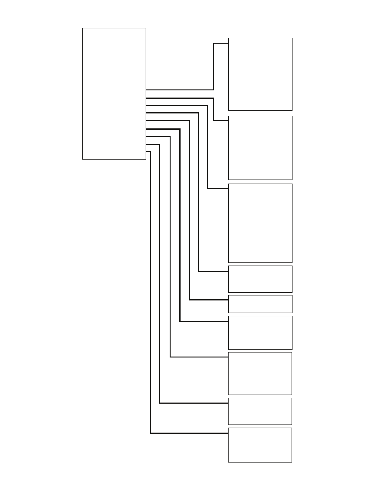
Menu structure (part 2)
Page 5 of 32
*Main Menu*
PINs & Access
System Support
Serial Comms
Pager Setup
Engineer Ctrl
Time & Date
Radio Setup
Output Setup
Logging
Relay Setup
Remote Rxers
Direct Inputs
Network
Txer Grouping
Bus I/O
*Radio Setup*
Add Transmitter
Txer Details
Set Radio Rules
Replace Txer
Suspend Txer
Reinstate Txer
Test Routines
Delete Transmitter
*Binary Outputs*
Test Outputs
Output Latch Times
Output Permissions
Output On Reasons
Output O Reasons
Re-name Output
Default Outputs
*Event Logging*
View Last Incident
View Log At Date
View Entire Log
View Log Group
Prnt Last Incident
Print Log By Date
Print Entire Log
Edit Incident Log -
- Priority
*Internal Relays*
View Relay Assigns
Chg Relay Assigns
*Remote Rxers*
Receivers Found
*Hardwired Inputs*
View Input Congs
Chg Input Congs
Current States
*X25 Network*
Network Device
Network RIN
Retain ‘Clears’
Monitor Link
*T-Groups*
View Grouping
Change Grouping
*I/O Modules*
View Modules
Monitor Link
ReScan I/O
Page 6

Introduction
The Iris+ is a wireless personal attack system ideal for use in all types of nancial, industrial and
commercial premises, where sta need the security of a personal attack alarm with total
mobility. The use of the latest techniques in design with the extensive use of surface mount
technology and microprocessors makes Iris+ a highly reliable, exible and user friendly system.
With most of the systems features under software control, Iris+ can easily be congured to
meet a specic customers requirements. Communication with the user is via a Liquid Crystal
Display (LCD), which shows the system status at all times.
Capable of identifying 256 individual transmitters, extensive event and historic logs, Personal
Identication Number (PIN) access and antenna tamper are just a few of the features oered by
Iris+. The wide range of features and facilities incorporated into Iris+ are normally only found in
full alarm control equipment, making Iris+ unique in wireless personal attack systems and a
leader in the eld.
The Iris+ system consists of a single xed receiver unit, the required number of transmitter
units and ancillary equipment dependant upon application. The Iris+ receiver is installed
within a rigid casing and mounted at a predetermined location, while the transmitters can be
installed into portable push-button Units, xed money clip units or xed contact operated
units. In addition the Iris+ will accept up to eight hard wired inputs via an input module.
Note: Regular users of the Iris system will notice that the latest version of Iris+ comes with the
added benets of a rened PCB layout and all software features unlocked as standard. The Iris+
industry renowned ease of operation and functionality remain exactly the same.
Tools & test equipment
No special test equipment is needed when installing the receiver. Only standard hand tools are
required to install and commission the system.
Page 6 of 32
Page 7
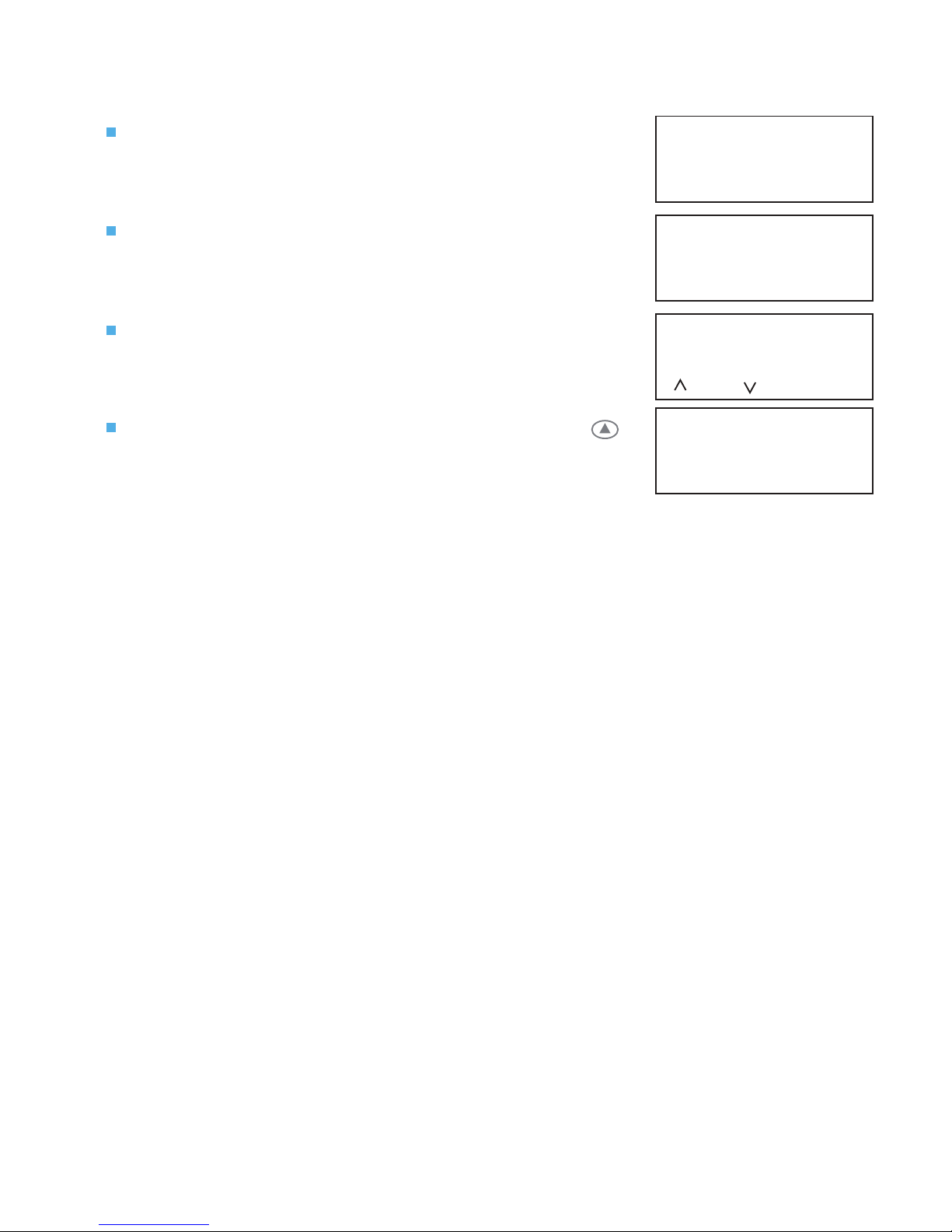
Accessing the engineering menus
To access the engineering menus, follow the steps listed below:
Once powered and the Iris+ has completed system and
conguration checks, the LCD screen will display:
Turn the front panel key to reset. The screen will change
to display:
Press the 0 key, the screen will now change to display:
Enter the engineering default PIN: 221100 and press .
The screen will change to display:
System Clear
08/05/18 13:26
*** SYSTEM RESET ***
13:26
Enter Your PIN
For Menus > _
=Done =Del 13:26
| ** Main Menu ** |
> Pins & Access <
| System Support |
2=Help 13:27
The maximum range between the Iris+ receiver and any transmitter is dependant upon the
environment in which the system is operating. Iris+ has a range of typically 250 metres in open
line of sight (dependant on the type of aerial used). The actual range achieved is determined
by local site conditions and how well the system has been installed.
When selecting a site for the receiver, the installing engineer should be aware that the aerial
has to be as far away from other electrical / electronic equipment as possible and a minimum
of 2 metres from any such equipment. Locating the receiver closer than this will eect the
systems performance. Metal objects such as ling cabinets, pipe work, radiators and air
conditioning ducts will also adversely eect the performance of the system if they are too near
the receivers antenna.
Before nal installation, carry out site tests to ensure that the system gives the site coverage
required at the position chosen.
With the Iris+ receiver as close to its proposed position as possible, t the antenna to the BNC
socket on top of the receiver and connect power to the receiver. On power-up the Iris+ will
perform a Warm Start and then display the System Clear message on the Liquid Crystal Display
(LCD) screen.
Receiver and transmitter location
Page 7 of 32
Page 8
Checking background interference levels
Access the Main Menu by following the operations listed under the previous ‘Accessing the
engineering menus ’ section.
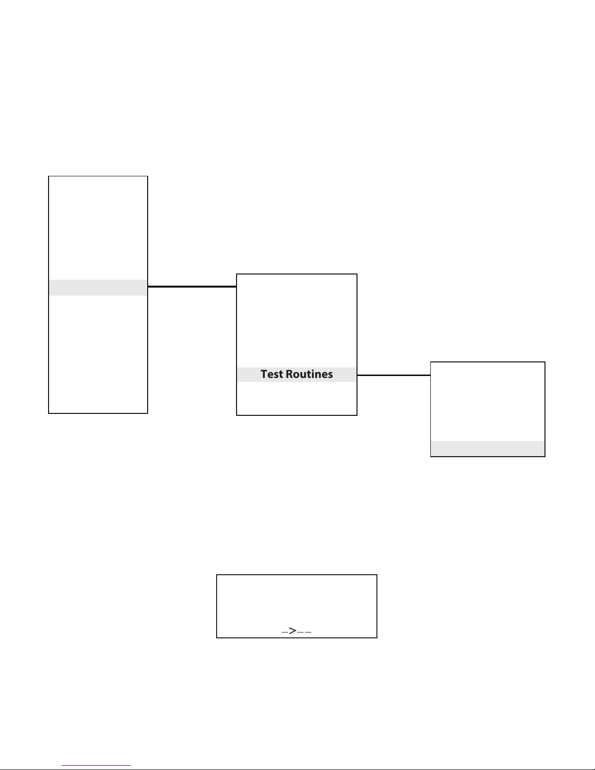
The Iris+ should now be set up to Monitor Background Signals as their presence at a high level
may eect the performance of the system. To enter this mode from the Main Menu select;
Radio Setup > Test Routines > Monitor Carrier.
Monitoring Carrier
Level = 26
Highest = 27
13:35
Page 8 of 32
*Test Menu*
Monitor Signal
Min/Max Report
Call-In Report
Battery Report
Monitor Carrier
*Radio Setup*
Add Transmitter
Transmitter Details
Replace Transmitter
Suspend Transmitter
Reinstate Transmitter
Test Routines
Delete Transmitter
*Main Menu*
PINs & Access
System Support
Serial Comms
Pager Setup
Engineer Ctrl
Time & Date
Radio Setup
Output Setup
Logging
Relay Setup
Remote Rxers
Direct Inputs
Network
Txer Grouping
Bus I/O
With Iris+ in Monitor Carrier mode the screen will show any background signals on and around
the frequency at which Iris operates. A typical screen shot is shown below. NOTE: Background
signals are generated by other electronic equipment such as computers, Fax machines, mobile
phones, surveillance cameras.
An acceptable level of background noise is between 0 and 55. Any higher indication may
adversely eect the performance of the system. If the level is shown to be high, there are a
number of steps that can be taken to reduce the reading, these are outlined overleaf.
Page 9

How to reduce interference
Step 1 Move the receiver away from likely source of interference.
Step 2 Fit a high gain UHF antenna to the receiver. EMS Part number 7328.
Step 3 Add a Remote Receiver to the system. EMS Part number 7258.
Step 4 Add a Transponder to the system. EMS Part number 7723.
Using one or a combination of the above it should be possible to reduce the background
carrier signal at the Iris+ receiver to an acceptable level.
Should the above steps fail to suitably reduce interference, contact EMS Technical Support for
more information.
Monitoring transmitter signals
With the Iris+ key turned to the test position, tested transmitter’s unique identities will
displayed on the screen, along with their signal strength readings. A typical screen shot is
shown below.
Ensure that all transmitters are tested. The maximum reading obtainable is 255, however in
practice this reading is almost never attained. Any reading 30 above the background carrier
gure is acceptable, although the higher the signal the better overall performance will be
achieved by the system.
For more information on identifying the background carrier, refer to the ‘Checking background
interference levels’ section, on page 8.
Where results are found not to be acceptable, taking the previously outlined ‘how to reduce
interference’ steps, will improve the reception from distant transmitters giving weak signals.
Once testing is complete, turn the Iris+ key to the clear position.
Handpush 013 TEST
230
Alarm
to END 13:35
Page 9 of 32
Page 10

Installation
The Iris+ receiver consists of two sections, rstly the front casing which houses the receiver /
processor PCB and secondly the rear casing which houses the external connection PCB. The
installation of the Iris+ receiver requires the separation of the two sections and the xing of the
rear back box section to the wall. To complete the installation the front casing is then
re-assembled onto the rear back box. The following paragraphs outline the installation in a
step by step format;
1 Open lid 2 Remove retaining screws
4 Remove wing nuts
Remove the two circled
front retaining screws.
Remove the four
circled M4 wing nuts.
3 Open unit
Open the unit, by
lifting the display.
5 Remove front section
The front section of
the unit can now be
separated from the
back box.
1 2 3
4 5 6
7 8 9
0
MENU
SELECT
HELP
MENU
ESCAPE
CHARACTER
LEFT
CHARACTER
ENTER
CHARACTER
RIGHT
CURSOR
LEFT
CHARACTER
TEN RIGHT
CURSOR
RIGHT
MENU DOWN
/ DELETE
PIN ACCESS /
SPACE
MENU
UP / DONE
RADIO RX
AERIAL
TAMPER
TAMPER
ENG PORT
ENABLE
TX OV RX
ENG RS232
RXTX
NORMAL
OPERATION
END OF
BUS
ON
ALARM
RLY 1 RLY 2 RLY 3
SYSTEM
FAULT POWER
RESET
POWER
0V 12V
BATTERY
ON
JP9
USB
BUSY
USB-BOOT
NORMAL
PAGER
RX TX
AUX
RX TX
RS485
RX VALID TX
Iris II
ENG
PORT
0V
RX
TX
+3V3
3 WAY KEY
SWITCH
COMMON
POS 3
POS 2
POS 1
DISABLE
1.25A Fuse
RLY2
CON3
L1
BOX
TAMPER
1CON5
1CON4
IC1
IC2 IC3 IC4
Iris +12V OUT
INPUT 8
INPUT 7
INPUT 6
INPUT 5
INPUT 4
INPUT 3
INPUT 2
INPUT 1
OPTO 0V
Iris 0V OUT
0V
+12V
A
COM
B
A
COM
B
A
COM
B
N.O
COM
N.C
POWER
SUPPLY
RELAY3RELAY2RELAY
1
ALARM
RELAY
HARDWIRED INPUTS
CTS
RX
0V
DTR
TX
PAGER 232
OUT-
OUT+
IN-
IN+
A
B
A
B
+
-
RX
0V
TX
RS485
AUX
RS232
TAMPER
IN
TAMPER
OUT
REMOTE
BUZZER
6 Remove cable entry points
Remove the cable
entry blanking plates
shown, as necessary.
Be careful not to
damage the printed
circuit board within
the unit.
1.25A Fuse
RLY2
CON3
L1
BOX
TAMPER
1CON5
1CON4
IC1
IC2 IC3 IC4
Iris +12V OUT
INPUT 8
INPUT 7
INPUT 6
INPUT 5
INPUT 4
INPUT 3
INPUT 2
INPUT 1
OPTO 0V
Iris 0V OUT
0V
+12V
A
COM
B
A
COM
B
A
COM
B
N.O
COM
N.C
POWER
SUPPLY
RELAY3RELAY2RELAY
1
ALARM
RELAY
HARDWIRED INPUTS
CTS
RX
0V
DTR
TX
PAGER 232
OUT-
OUT+
IN-
IN+
A
B
A
B
+
-
RX
0V
TX
RS485
AUX
RS232
TAMPER
IN
TAMPER
OUT
REMOTE
BUZZER
1 2 3
MENU
SELECT
HELP
MENU
ESCAPE
RADIO RX
AERIAL
TAMPER
TAMPER
ENG PORT
ENABLE
TX OV RX
ENG RS232
RXTX
NORMAL
OPERATION
END OF
BUS
ON
ALARM RLY 1 RLY 2 RLY 3
SYSTEM
FAULT POWER
RESET
POWER
0V 12V
BATTERY
ON
JP9
USB
BUSY
USB-BOOT
NORMAL
PAGER
RX TX
AUX
RX TX
RS485
RX VALID TX
Iris II
ENG
PORT
0V
RX
TX
+3V3
3 WAY KEY
SWITCH
COMMON
POS 3
POS 2
POS 1
DISABLE
Open the lower
lid to expose the
keypad and LCD
display.
Page 10 of 32
1 2 3
4
5 6
7 8 9
0
Universe + (Plus) Range
CLEAR
RESET
TEST
1 2 3
4 5 6
7 8 9
0
MENU
SELECT
HELP
MENU
ESCAPE
CHARACTER
LEFT
CHARACTER
ENTER
CHARACTER
RIGHT
CURSOR
LEFT
CHARACTER
TEN RIGHT
CURSOR
RIGHT
MENU DOWN
/ DELETE
PIN ACCESS /
SPACE
MENU
UP / DONE
1 2 3
4
5 6
7 8 9
0
Universe + Range
CLEAR
RESET
TEST
1 2 3
4 5 6
7 8 9
0
MENU
SELECT
HELP
MENU
ESCAPE
CHARACTER
LEFT
CHARACTER
ENTER
CHARACTER
RIGHT
CURSOR
LEFT
CHARACTER
TEN RIGHT
CURSOR
RIGHT
MENU DOWN
/ DELETE
PIN ACCESS /
SPACE
MENU
UP / DONE
Page 11

7 Check rear tamper 8 Fix back box
Oer the back box to the wall.
Ensure that the rear tamper switch
operates. If necessary, remove the unit
from the wall and carefully adjust the
microswitch arm.
All four circled
positions must
be used, to
ensure a rm
xing.
9 Back box connection wiring
All external connections should now be made within the back box.
Iris+ must NOT be used as a junction box or cable termination point as this will
adversely eect the performance of the system.
The Iris+ case must be earthed. A separate earthing tag is provided and is shown above.
The Iris+ requires a 12Vdc supply. The 0v line must NOT be connected to the same point
as the case earth.
Note: details of other back box connections, can be seen on pages 13 & 14.
Earth connection
1.25A Fuse
RLY2
CON3
L1
BOX
TAMPER
1CON5
1CON4
IC1
IC2 IC3 IC4
Iris +12V OUT
INPUT 8
INPUT 7
INPUT 6
INPUT 5
INPUT 4
INPUT 3
INPUT 2
INPUT 1
OPTO 0V
Iris 0V OUT
0V
+12V
A
COM
B
A
COM
B
A
COM
B
N.O
COM
N.C
POWER
SUPPLY
RELAY
3
RELAY
2
RELAY
1
ALARM
RELAY
HARDWIRED INPUTS
CTS
RX
0V
DTR
TX
PAGER 232
OUT-
OUT+
IN-
IN+
A
B
A
B
+
-
RX
0V
TX
RS485
AUX
RS232
TAMPER
IN
TAMPER
OUT
REMOTE
BUZZER
12Vdc power
1.25A Fuse
RLY2
CON3
L1
BOX
TAMPER
1CON5
1CON4
IC1
IC2 IC3 IC4
Iris +12V OUT
INPUT 8
INPUT 7
INPUT 6
INPUT 5
INPUT 4
INPUT 3
INPUT 2
INPUT 1
OPTO 0V
Iris 0V OUT
0V
+12V
A
COM
B
A
COM
B
A
COM
B
N.O
COM
N.C
POWER
SUPPLY
RELAY3RELAY2RELAY
1
ALARM
RELAY
HARDWIRED INPUTS
CTS
RX
0V
DTR
TX
PAGER 232
OUT-
OUT+
IN-
IN+
A
B
A
B
+
-
RX
0V
TX
RS485
AUX
RS232
TAMPER
IN
TAMPER
OUT
REMOTE
BUZZER
Page 11 of 32
Page 12

10 Re-attach front section 11 Replace wing nuts
Re-attach the front
section on to the back
box, ensuring a rm
connection.
Replace all four
M4 wing nuts, and
fully tighten to
ensure a secure
connection.
1 2 3
4 5 6
MENU
SELECT
HELP
MENU
ESCAPE
CHARACTER
LEFT
CHARACTER
ENTER
CHARACTER
RIGHT
RADIO RX
AERIAL
TAMPER
TAMPER
ENG PORT
ENABLE
TX OV RX
ENG RS232
RXTX
NORMAL
OPERATION
END OF
BUS
ON
ALARM RLY 1 RLY 2 RLY 3
SYSTEM
FAULT POWER
RESET
POWER
0V 12V
BATTERY
ON
JP9
USB
BUSY
USB-BOOT
NORMAL
PAGER
RX TX
AUX
RX TX
RS485
RX VALID TX
Iris II
ENG
PORT
0V
RX
TX
+3V3
3 WAY KEY
SWITCH
COMMON
POS 3
POS 2
POS 1
DISABLE
1 2 3
4 5 6
7 8 9
0
MENU
SELECT
HELP
MENU
ESCAPE
CHARACTER
LEFT
CHARACTER
ENTER
CHARACTER
RIGHT
CURSOR
LEFT
CHARACTER
TEN RIGHT
CURSOR
RIGHT
MENU DOWN
/ DELETE
PIN ACCESS /
SPACE
MENU
UP / DONE
RADIO RX
AERIAL
TAMPER
TAMPER
ENG PORT
ENABLE
TX OV RX
ENG RS232
RXTX
NORMAL
OPERATION
END OF
BUS
ON
ALARM
RLY 1 RLY 2 RLY 3
SYSTEM
FAULT POWER
RESET
POWER
0V 12V
BATTERY
ON
JP9
USB
BUSY
USB-BOOT
NORMAL
PAGER
RX TX
AUX
RX TX
RS485
RX VALID TX
Iris II
ENG
PORT
0V
RX
TX
+3V3
3 WAY KEY
SWITCH
COMMON
POS 3
POS 2
POS 1
DISABLE
1.25A Fuse
RLY2
CON3
L1
BOX
TAMPER
1CON5
1CON4
IC1
IC2 IC3 IC4
Iris +12V OUT
INPUT 8
INPUT 7
INPUT 6
INPUT 5
INPUT 4
INPUT 3
INPUT 2
INPUT 1
OPTO 0V
Iris 0V OUT
0V
+12V
A
COM
B
A
COM
B
A
COM
B
N.O
COM
N.C
POWER
SUPPLY
RELAY3RELAY2RELAY
1
ALARM
RELAY
HARDWIRED INPUTS
CTS
RX
0V
DTR
TX
PAGER 232
OUT-
OUT+
IN-
IN+
A
B
A
B
+
-
RX
0V
TX
RS485
AUX
RS232
TAMPER
IN
TAMPER
OUT
REMOTE
BUZZER
12 Close display 13 Replace retaining screws
Close the display.
Replace the two circled
front retaining screws.
14 Apply power 15 Installation complete
Power can now be
applied.
After approx. 5 seconds,
the LCD screen should
display ‘System Clear’ as
shown.
The installation is now
complete.
The system should now
be fully tested. See
page 15.
1 2 3
4
5 6
7 8 9
0
Page 12 of 32
1 2 3
4 5 6
7 8 9
0
MENU
SELECT
HELP
MENU
ESCAPE
CHARACTER
LEFT
CHARACTER
ENTER
CHARACTER
RIGHT
CURSOR
LEFT
CHARACTER
TEN RIGHT
CURSOR
RIGHT
MENU DOWN
/ DELETE
PIN ACCESS /
SPACE
MENU
UP / DONE
1 2 3
4
5 6
7 8 9
0
Universe + Range
CLEAR
RESET
TEST
1 2 3
4 5 6
7 8 9
0
MENU
SELECT
HELP
MENU
ESCAPE
CHARACTER
LEFT
CHARACTER
ENTER
CHARACTER
RIGHT
CURSOR
LEFT
CHARACTER
TEN RIGHT
CURSOR
RIGHT
MENU DOWN
/ DELETE
PIN ACCESS /
SPACE
MENU
UP / DONE
Page 13

Iris+ back box connections explained
9 way D connector
25 way D connector
RS485
(OUT -, OUT +, IN - & IN +)
TAMPER
(IN A, IN B, OUT A & OUT B)
REMOTE BUZZER
(+ & -)
Aux 232
(RX, 0V & TX)
Rear Tamper
Pager 232
(CTS, RX, 0V, DTR & TX)
Power supply
(0V & 12V)
Relay 3
(A, COM & B)
Relay 2
(A, COM & B)
Relay 1
(A, COM & B)
Alarm Relay
(NO, COM, NC)
Used for connection to the Iris+ front box.
Used for connection to the Iris+ front box.
RS485 Bus used for remote receiver/output module connection
with the Iris+ receiver. OUT - and OUT + are taken to the remote
receivers/output modules IN - and IN + respectively.
A Link is factory tted between Tamper IN A and IN B terminals.
This allows operation of the front tamper switch but disables
the rear tamper switch. If the rear tamper switch is also required
two links should be made, these are between Tamper In A to
Tamper Out A and Tamper In B to Tamper Out B.
The remote buzzer output allows up to a 500mA buzzer to be
connected to the receiver, which will follow the operation of the
units internal buzzer.
The Aux 232 is a serial RS232 port which can be used for
importing and exporting system information between the Iris+
and a terminal programme.
This is a two way connector pre-wired from the units rear
tamper switch.
The Pager 232 connector is a RS232 port which is used for
connection to an EMS text pager transmitter . The port is also
used to receive information from EMS alarm control equipment
and also pass this to the pager transmitter.
0Vdc and 12Vdc input to the Iris+ unit. Current draw is 80mA
standard at 12Vdc supply and 250mA at 12Vdc with the Back lit
display activated.
Programmable non energised 1 Amp relay output.
Programmable non energised 1 Amp relay output.
Programmable non energised 1 Amp relay output.
Programmable energised 1 Amp relay output.
Page 13 of 32
Page 14

Iris 12V OUT
INPUT 8
INPUT 7
INPUT 6
INPUT 5
INPUT 4
INPUT 3
INPUT 2
INPUT 1
OPTO 0V
Iris 0V OUT
12Vdc output which can be used if required, to trigger inputs 1-8.
Hardwired Input 8 programmable for N/O or N/C operation.
5-12Vdc applied or removed to trigger dependant on
programming.
Hardwired Input 7 programmable for N/O or N/C operation.
5-12Vdc applied or removed to trigger dependant on
programming.
Hardwired Input 6 programmable for N/O or N/C operation.
5-12Vdc applied or removed to trigger dependant on
programming.
Hardwired Input 5 programmable for N/O or N/C operation.
5-12Vdc applied or removed to trigger dependant on
programming.
Hardwired Input 4 programmable for N/O or N/C operation.
5-12Vdc applied or removed to trigger dependant on
programming.
Hardwired Input 3 programmable for N/O or N/C operation.
5-12Vdc applied or removed to trigger dependant on
programming.
Hardwired Input 2 programmable for N/O or N/C operation.
5-12Vdc applied or removed to trigger dependant on
programming.
Hardwired Input 1 programmable for N/O or N/C operation.
5-12Vdc applied or removed to trigger dependant on
programming.
Requires 0Vdc to be applied to enable a positive voltage to
trigger inputs 1-8.
0Vdc output which is normally linked to the OPTO 0V connection
to enable a positive voltage to trigger inputs 1-8.
Page 14 of 32
Page 15

Post installation testing
Having installed the Iris+ receiver and transmitters, re-test all transmitters from their xed
positions.
With the Iris+ key turned to the test position, tested transmitter’s unique identities will
displayed on the screen, along with their signal strength readings. A typical screen shot is
shown below.
Ensure that all transmitters are tested. The maximum reading obtainable is 255, however in
practice this reading is almost never attained. Any reading 30 above the background carrier
gure is acceptable, although the higher the signal the better overall performance will be
achieved by the system.
For more information on identifying the background carrier, refer to the ‘Checking background
interference levels’ section, on page 8.
Where results are found not to be acceptable, taking the previously outlined ‘how to reduce
interference’ steps, will improve the reception from distant transmitters giving weak signals.
Once testing is complete, turn the Iris+ key to the clear position.
Page 15 of 32
Handpush 013 TEST
230
Alarm
to END 13:35
Page 16

Operating instructions
Keyswitch
TEST position; all transmitters or hard wired inputs programmed to the system are able to be
tested. A full alarm / local transmission or hard wired input activation will be acknowledged on
the LCD screen and the buzzer will sound for approximately 1 second. With the unit set to the
factory preset, whilst in this key position none of the relays should be observed to change state
upon receipt of a valid transmission or hard wired input activation.
RESET position; all outstanding events will be cleared. Access to the system menus can be
gained by pressing the 0 (zero) key and entering a valid user PIN number. With the unit set to
the factory presets, whilst in this key position none of the relays should be observed to change
state upon receipt of a valid transmission or hard wired input activation.
CLEAR position; any alarm transmission(s) will be acknowledged on the LCD screen and the
alarm relay will latch until cleared by moving the keyswitch to reset. A local transmission will be
acknowledged on the screen (providing an alarm transmission has not been received), the
local relay will change state for a period of approximately 4 seconds and the buzzer will then
sound until the keyswitch is moved to the reset position. Use of the or buttons allows
the user to step through the events in the incident log.
Display
The 80 character LCD display shows the current state of the system, or displays any activations
not yet cleared to the event log. Information is also provided on the bottom line about the
current time and date. A single alpha numeric digit, preceding the time, displays information
about the receipt of transmissions or warnings of RFI (radio frequency interference) and power
supply failure.
Page 16 of 32
Page 17

Adding a transmitter
To add any additional transmitters, access the Main Menu by following the operations listed
under the previous ‘Accessing the engineering menus ’ section.
Now, follow the steps listed below:
Press the button four times, the screen will now
display:
Press the button. The screen will change to display:
Press the button. The screen will change to display:
(See Appendix 1 for details of transmitter options)
Use the or arrow keys to highlight the type of
transmitter to be added and press the button, the
screen will change to display the options available
(handpush screen shown):
Press the or arrows to highlight the transmitter
action required and press the button. The screen will
change to display (handpush screen shown):
Operate the unit to generate a transmission and the
screen will display:
After a short period of time the screen will change to
display (handpush screen shown):
Using the same operation, once again generate a
transmission, after a short period of time the screen will
change to display (handpush screen shown):
| Time and Date |
> Radio Setup <
| Output Setup |
2 = Help 13: 47
1
| ** Radio Setup ** |
> Add Transmitter <
| Txer Details |
2 = Help 13: 47
1
| Add Transmitter |
> Add Handpush <
| Add Moneyclip |
2 = Help 13: 47
| Handpush Type |
> Opposed Action <
| Non-Opposed |
2 = Help 13: 47
1
1
Operate Transmitter
NOW or press
Escape to cancel
13: 48
Release all buttons
NOW
13: 48
Operate Transmitter
Again or press
Escape to cancel
13: 48
Hand Push 001
Added
Push any key
13: 48
You may now add additional transmitters, by repeating the above steps. If no further
transmitters are to be added, then escape from this menu by pressing the button or
returning the key to CLEAR.
3
Page 17 of 32
Page 18

Naming a transmitter
To change the name of any transmitters, access the Main Menu by following the operations
listed under the previous ‘Accessing the engineering menus ’ section.
Now, follow the steps listed below:
Press the button four times. The screen will now
display:
Press the button. The screen will change to display:
Press the button. The screen will change to display:
Press the button. The screen will change to display:
Press the button once. The screen will display:
Press the button. The screen will display:
Generate a transmission and the screen will change to
display:
After a short period of time the screen will display:
Once again generate a transmission, the screen will
change to display:
Note: the current selected character is shown above the
centre bar.
| Time and Date |
> Radio Setup <
| Output Setup |
2 = Help 13: 49
1
| ** Radio Setup ** |
> Add Transmitter <
| Txer Details |
2 = Help 13: 49
1
| Add Transmitter |
> Txer Details <
| Set Radio Rules |
2 = Help 13: 49
1
1
| - Txer Details - |
> Name by Number <
| Name by Tx |
2=Help 13: 49
| Name by Number |
> Name by Tx <
| View Names |
2=Help 13: 49
| |
| |
4< IJKL M NOPQR >6
2=Help 13: 50
Operate Transmitter
NOW or press
Escape to cancel
13: 50
Release all buttons
NOW
13: 50
Operate Transmitter
Again or press
Escape to cancel
13: 50
Page 18 of 32
Page 19

Page 19 of 32
By using the button to move left or the button to move right, move to the letter or
number required. Press button to select the character.
Repeat until all letters have been selected. Once completed press the button to save the
information.
Repeat the previous steps, for any other transmitters requiring naming.
Once complete, you may now escape from this menu by pressing the button until the
SYSTEM RESET message appears or by returning the key to the CLEAR position.
4 6
5
3
1 2 3
4 5 6
7 8 9
0
MENU
SELECT
HELP
MENU
ESCAPE
CHARACTER
LEFT
CHARACTER
ENTER
CHARACTER
RIGHT
CURSOR
LEFT
CHARACTER
TEN RIGHT
CURSOR
RIGHT
MENU DOWN
/ DELETE
PIN ACCESS /
SPACE
MENU
UP / DONE
Page 20

Page 20 of 32
Deleting a transmitter
To delete a transmitter, access the Main Menu by following the operations listed under the
previous ‘Accessing the engineering menus’ section.
Now, follow the steps listed below:
Press the button four times. The screen will now
display:
Press the button. The screen will change to display:
Press the button seven times. The screen will change
to display:
Press the button. The screen will change to display:
Press the button once. The screen will change to
display:
Press the button. The screen will change to display:
Enter the transmitter number to be deleted and the
screen will change to (screen shown for Handpush 001):
Press 1 (one) to accept and the screen will change to:
Press any key and you will return to the delete transmitter
menu.
| Time and Date |
> Radio Setup <
| Output Setup |
2 = Help 13: 51
1
| ** Radio Setup ** |
> Add Transmitter <
| Txer Details |
2 = Help 13: 51
| Reinstate Transmitter |
| Test Routines |
> Delete Transmitter <
2 = Help 13: 51
1
| Delete Transmitter |
> Delete by Number <
| Delete by Tx |
2=Help 13: 51
> Delete Transmitter <
| Delete by Number |
| Delete by Tx |
2=Help 13: 51
1
Enter Transmitter
Number: _
= Done = Del 13: 52
Hand Push 001
Delete ?
1=Yes 0=No 13: 52
Hand Push 001
Deleted
Press Any Key 13: 52
Repeat the above steps for any further transmitters to be deleted, or press the button three times
to escape to the main menu.
3
Page 21

Page 21 of 32
Press the button. The screen will change to display:
Decide which type of user you are to add and whether they
will use a 4 or 6 digit PIN.
Press the button until the screen displays Add 6
Digit User or Add 4 Digit User (as chosen in the
previous step):
Add a new user
To gain access to Iris+ a valid PIN number must be entered from the keypad. Each PIN programmed
into the system will have a security level associated with it, this is know as the access level and will
determine which features are available to the holder of a particular PIN. The chart below gives details
on 2 of the 6 access levels available, for further details of the access levels consult the ‘Engineers
Programming Manual’.
Access level
11 - 50
51 - 80
Level name
General user
Reset user
Purpose
Restricted menu options
Restricted menu options
PIN number
4 or 6 digit
4 or 6 digit
The screen will now show:
Press any key and the screen will change to display:
The current selected character is shown above the centre
bar.
By using the button to move left or the button to
move right, move to the letter or number required. Press
the button to select the character.
When you have completed the selections press the
button.
The screen will now change to display:
Enter the user’s access level and press the button to
accept the selection.
The screen will now change to display:
Enter the New
Users Name
Push Any Key 13: 55
| |
| |
4< HIJKL M NOPQRS >6
2=Help 13: 55
| KAREN |
| |
4< IJKL M NOPQRST >6
2=Help 13: 55
Enter User 02’s
Security Level
(2-99): _
=Done =Del 13: 55
4 6
5
| ** Pins & Access ** |
> User Log On <
| View Users |
2=Help 13:55
| Change PIN |
> Add 6 Digit User <
| Add 4 Digit User |
2=Help 13:55
Now, follow the steps listed below:
Access the Main Menu by following the operations listed under the previous ‘Accessing the
engineering menus ’ section.
1
| Change PIN |
> Add 6 Digit User <
| Add 4 Digit User |
2=Help 13:55
Page 22

Page 22 of 32
Press the button once and the screen will display:
Press the button once and the screen will display:
Use the key to highlight the user entered and press
the button once. The screen will now change to
display:
Enter the chosen PIN number and press the button.
The screen will change to:
Once again enter the chosen PIN number and press the
button. The screen will change to display:
Pressing any key will return you to the pins and access
menu.
| View Users |
> Change Pin <
| Add 6 Digit User |
2=Help 13:55
| * Change PIN for ? * |
> 00/ Engineer, 01 <
| 02/ Karen, 10 |
2=Help 13:56
1
1
Enter Karen’s
New 6 Digit
PIN No.: _
=Done =Del 13:56
Conrm Karen’s
New 6 Digit
PIN No.: _
=Done =Del 13:56
Changed PIN for
User 02 ‘Karen’
* * Press Any Key * * *
13:56
NOTE: If the re-entered pin is incorrect or is one of the 25% automatically rejected for security
reasons, re-enter the PIN number.
Page 23

Page 23 of 32
Transmitter grouping
Each of the transmitters programmed into Iris can be allocated to a transmitter group. These groups
can then be assigned to make one or more relays operate. This will allow a wide variety of options to
be set up where designated transmitters will operate specic relays.
The Menu structure for the Grouping Task is shown below.
*T-Groups*
View Grouping
Change Grouping
*Main Menu*
PINs & Access
System Support
Serial Comms
Pager Setup
Engineer Ctrl
Time & Date
Radio Setup
Output Setup
Logging
Relay Setup
Remote Rxers
Direct Inputs
Network
Txer Grouping
Bus I/O
Change Grouping: Selecting this option allows the various groups to be altered. There are a
maximum of 16 groups available. Each group can have its event congured. The event can be best
described as the way the group will respond to a signal. The valid options are shown below:
Event options
Alarm
Local
P-Call
X-Alarm
X-Local
Any
None
Group response
An Alarm signal from any transmitter in the group.
A Local signal from any transmitter in the group.
A P-Call alarm signal from any personnel call transmitter in the group.
Any Local or P-Call signal but NOT an Alarm signal from any transmitter
in the group.
Any Alarm or P-Call signal but NOT a Local signal from any transmitter in
the group.
Any signal from any transmitter in the group.
No operation
Page 24

Page 24 of 32
Example transmitter grouping
The following example shows how to assign an alarm transmission from handpush 001, to transmitter
group 1 (Tgroup1). Follow the steps below:
Access the Main Menu by following the operations listed under the previous ‘Accessing the
engineering menus ’ section.
Press the button until the screen displays:
Press the button. The screen will change to display:
Press the button until the screen displays:
Press the button until the required group is displayed:
In this example, Tgroup No:1
Press the button once and the screen will display:
Press the button until the required action is displayed:
In this example Event: Alarm
Press the button once and the screen will display:
Press the button. The screen will change to show a
list of the transmitters programmed into the system:
If required, press & until the required device is selected.
Press the button to select the required transmitter. The
screen will change to display:
Followed by:
Press the 3 key twice to return to the Main Menu.
| Network |
> Txer Grouping <
| Bus I/O |
2=Help 14:00
| ** T - Groups ** |
> View Grouping <
| Change Grouping |
2=Help 14:00
1
| View Grouping |
> Change Grouping <
| ^^^^^^^^^^^^^^^^^ |
2=Help 14:00
| ** T - Groups ** |
> Tgroup No: 1 <
| Event : None |
2=Help 14:00
1
| TGroup No: 1 |
> Event: None <
| No of Items: 0 |
2=Help 14:00
1
| TGroup No: 1 |
> Event: Alarm <
| No of Items: 0 |
2=Help 14:00
| Event: Alarm |
> No of Items: 0 <
| ^^^^^^^^^^^^^^^^^ |
2=Help 14:01
1
| ** Select Item ** |
> Hand Push 001 <
|---------------------------------|
2=Help 14:01
Saving Data
Please Wait
2=Help 14:01
1
| Event: Alarm |
> No of Items: 1 <
| ^^^^^^^^^^^^^^^^^ |
2=Help 14:01
Note: transmitter groups must now be allocated to relay outputs. See overleaf.
Page 25

Page 25 of 32
Relay output conguration
Available events that can be used to make the Iris+ relay outputs operate are as follows:
NOTHING
GROUP: HUA ALARM*
GROUP: HUA LOCAL*
GROUP: DISPLAY*
GROUP: FAULT*
GROUP: LOG *
GROUP: TAMPER*
GROUP: RECORD*
GROUP: ALARM*
GROUP: LOCAL*
GROUP: NETWORK*
EVENT: IRIS TO CLEAR
EVENT: IRIS TO RESET
EVENT: ARMING THE SYSTEM
EVENT: IRIS TO TEST
EVENT: TXER GROUP 1 ON
EVENT: TXER GROUP 2 ON
EVENT: TXER GROUP 3 ON
EVENT: TXER GROUP 4 ON
EVENT: TXER GROUP 5 ON
EVENT: TXER GROUP 6 ON
EVENT: TXER GROUP 7 ON
EVENT: TXER GROUP 8 ON
EVENT: TXER GROUP 9 ON
EVENT: TXER GROUP 10 ON
EVENT: TXER GROUP 11 ON
EVENT: TXER GROUP 12 ON
EVENT: TXER GROUP 13 ON
EVENT: TXER GROUP 14 ON
EVENT: TXER GROUP 15 ON
EVENT: TXER GROUP 16 ON
EVENT: ALARM
EVENT: MEDITILT ALARM
EVENT: CONTACT ALARM
EVENT: CALL IN FAIL
EVENT: ALARM STAGE 1 ON
EVENT: ALARM STAGE 1 OFF
EVENT: ALARM STAGE 2 ON
EVENT: ALARM STAGE 2 OFF
EVENT: PERSONNEL CALL
No action to be taken
Raid alarm transmissions
Raid local alert transmissions
Events to be displayed, not logged
Equipment failiure/malfunctions
Events to be logged when in clear
Tamper events
Events to be recorded (logged) at all times
General alarms transmissions
General local transmissions
Events sent over a network link
Events considered to be clear transmissions
Iris control keyswitch in the ‘reset’ position
Iris control keyswitch in the ‘clear’ position
Iris control keyswitch in the ‘test’ position
Transmitter group 1 is active (as used in the previous section)
Transmitter group 2 is active
Transmitter group 3 is active
Transmitter group 4 is active
Transmitter group 5 is active
Transmitter group 6 is active
Transmitter group 7 is active
Transmitter group 8 is active
Transmitter group 9 is active
Transmitter group 10 is active
Transmitter group 11 is active
Transmitter group 12 is active
Transmitter group 13 is active
Transmitter group 14 is active
Transmitter group 15 is active
Transmitter group 16 is active
Alarm from an alarm transmitter
Alarm transmitter has been in man down position for 45 seconds
Alarm transmission from a contact operated transmitter
Transmitter has failed to call in to the Iris system
An active stage 1 alarm condition
Stage 1 alarm conditon has cleared
An active stage 2 alarm condition
Stage 2 alarm conditon has cleared
Alarm transmission from a personnel call transmitter
* Note: Multiple ‘GROUP:’ type events can be assigned to a relay output
Page 26

Page 26 of 32
The following example shows how to congure Output 4 (Relay 3) to change state upon an alarm
transmission. This example could be used to operate a Piezo Sounder. Follow the steps listed below:
Access the Main Menu by following the operations listed under the previous ‘Accessing the
engineering menus ’ section.
Press the button until the screen displays:
Press the button. The screen will change to display:
Press the button until the screen displays:
Press the button. The screen will change to display:
Press the button. The screen will change to display:
Press the button until the screen displays the required
output to congure: In this example, Output 4.
Note: An alternative event type can be selected from pg25.
Press the button. The screen will change to display:
Press the button once and the screen will display:
Press the button until the screen displays the required
action:
In this example, Group: ‘Alarm’
Press the button. The screen will change to display:
Press the 3 key until SYSTEM RESET is displayed and turn
the keyswitch to the Clear position to exit the menu.
| Radio Setup |
> Output Setup <
| Logging |
2=Help 14:05
| ** Binary Outputs ** |
> Test Outputs <
| Output Latch Times |
2=Help 14:05
1
| Output Permissions |
> Output On Reasons <
| Output O Reasons |
2=Help 14:05
Output On Reasons
1 = Change On Reason
3 = Exit / Finish
2=Help 14:05
1
Edit on Reason
for Output 3
1 = deselect reason
2=Help 14:05
| * Select on Reason * |
> NOTHING <
|---------------------------------|
2=Help 14:05
1
|---------------------------------|
> Group: ‘Alarm’ <
|---------------------------------|
2=Help 14:06
1
| * Output on Reason * |
> 1 / ‘Un-named’ is <
| Switched on by |
2=Help 14:05
|-------------------------------- |
> 3 / ‘Un-named’ is <
| Switched on by |
2=Help 14:05
1
1
|---------------------------------|
>*REASON*SELECTED* <
| Group: ‘Alarm’ |
2=Help 14:06
Page 27

1.25A Fuse
RLY2
CON3
L1
BOX
TAMPER
1CON5
1CON4
IC1
IC2 IC3 IC4
Iris +12V OUT
INPUT 8
INPUT 7
INPUT 6
INPUT 5
INPUT 4
INPUT 3
INPUT 2
INPUT 1
OPTO 0V
Iris 0V OUT
0V
+12V
A
COM
B
A
COM
B
A
COM
B
N.O
COM
N.C
POWER
SUPPLY
RELAY
3
RELAY
2
RELAY
1
ALARM
RELAY
HARDWIRED INPUTS
CTS
RX
0V
DTR
TX
PAGER 232
OUT-
OUT+
IN-
IN+
A
B
A
B
+
-
RX
0V
TX
RS485
AUX
RS232
TAMPER
IN
TAMPER
OUT
REMOTE
BUZZER
Example relay wiring
The example below shows the wiring of the Piezo Sounder into Relay 3, to match the previously
detailed
Relay output conguration section:
Iris+ back box
Page 27 of 32
IC2 IC3 IC4
Iris +12V OUT
INPUT 8
INPUT 7
INPUT 6
INPUT 5
INPUT 4
INPUT 3
INPUT 2
INPUT 1
0V
+12V
A
COM
B
A
COM
B
A
COM
POWER
SUPPLY
RELAY
3
RELAY
2
RELAY
HARDWIRED INPUTS
CTS
RX
0V
DTR
TX
RS485
AUX
RS232
TAMPER
IN
TAMPER
OUT
REMOTE
BUZZER
12Vdc power inputBUZ+
BUZ-
12Vdc Piezo
Sounder
Important note:
This is an example
only. Any of the four
relay outputs could
be congured to drive the Piezo
Sounder. The relays can also be
used for many other
applications.
Page 28

Problem
No indications on the LCD
display, no buzzer
sounding.
‘P’ displayed preceding
time on LCD display
‘Main Receiver, Aerial
Tampered’ shown on
display and buzzer
sounding
‘Aerial Tampered, Call
Engineer, Antifalse’ shown
on display and buzzer
sounding
‘I’ displayed preceding
time on display
Persistent R.F.I.
‘Case Tampered’ shown on
display
Keyswitch does not
operate
‘Call In Fail’ shown on
display, with transmitter
ID
‘Call In Fail’ shown on
display, with transmitter
ID
Receiver does not
respond to a transmitter
Receiver does not
respond to a transmitter
Receiver does not
respond to a transmitter
Receiver does not
respond to a transmitter
Possible cause
No power to the system
Power below threshold of
10.2Vdc, +/- 0.3Vdc.
Aerial has been removed or
tampered with
Aerial not tted correctly or
tampered with
Local radio frequency
interference
Local radio frequency
interference
Case is tampered front or
back.
Connector lead not tted
correctly
Transmitter out of receiver
range
Transmitter battery has
expired
Transmitter not
programmed to system
Transmitter battery has
expired
Transmitter is not
compatible with system
Transmitter damaged
Action
Check power supply and fuses.
Re-power unit
Check power supply voltage
Check aerial is correctly tted
or replace aerial
Check aerial is correctly tted
or replace aerial
Refer to the
How to reduce
interference
section
Refer to the
How to reduce
interference
section
Check operation of front and
back tamper switches
Check connector lead is tted
correctly
Refer to the
How to reduce
interference
section
Replace transmitter batteries
Refer to the
Adding a
transmitter
section
Replace transmitter batteries
See appendix 1 for compatible
transmitters
Replace transmitter or return
to EMS for repair
Helpful hints
Page 28 of 32
1.25A Fuse
RLY2
CON3
L1
BOX
TAMPER
1CON5
1CON4
Page 29

Appendix
Product number
7500 variants
7910
7920
7920/AS
7920/PB
7920/PC
7930
7943
7970
7971
7972
Description
Portable transmitter
Moneyclip
Contact operated transmitter
Air switch operated transmitter
Push button operated transmitter
Pull cord operated transmitter
Asset protection transmitter
High power transmitter
Pendant transmitter with chain
Pendant transmitter without chain
Pendant transmitter with lanyard
Options
Opposed action
Non opposed
Triple action
Single action
Dual action
Single action
Dual action
Alarm N/O
Alarm N/C
Local N/O
Local N/C
Single action
Single action
Single action
Single action
Alarm N/O
Dual action
Single action
Opposed action
Glossary
*
Aerial Tamper
Call In Fail
I
P
R.F.I
System Clear
System Reset
Test All TX
*Carrier received (precedes time on display)
Aerial has been removed or tampered with Call In Fail Transmitter failed to
call in three successive times (precedes Txer Details)
Transmitter has failed to call in a rst or second time (log event only)
RFI Detected after a period of 30 seconds (precedes time on display)
12Vdc PSU below
10.2Vdc, +/- 0.3Vdc threshold (precedes time on display)
Radio Frequency Interference.
System now armed.
System resetting outstanding events.
Test full alarm, local and tamper (where applicable) for each transmitter
programmed to the system.
Page 29 of 32
Page 30

Technical Specications
Physical
Environmental
Operating frequency
RF sensitivity
Supply
Inputs
Outputs
Standards
Dimensions
Weight
Temperature
Humidity
Voltage
Max current
Complies with
H 195mm x W 296mm x D 110mm
4 kg
-10 to +55 degrees C
Up to 75% non-condensing
458.5 to 458.8 MHz
channel spacing 25khz (MPT 1329)
-120 dBm for 12 dB sinad NBFM radio strength
indication dynamic range of 60 dB AFC capture and
hold +/- 3 KHz
10 to 16Vdc
250mA @ 12Vdc (with back light activated)
Up to 256 wireless transmitters
Up to 8 hardwired inputs
4 programmable relay outputs
30V 28VA (1amp max) contacts
RS485 bus port
RS232 port
BS4737 intruder alarm systems
BS7042 high security intruder alarm systems
BS6799 (up to class 5) wire free intruder alarm
systems
EN50131 class 2 grade 2
MPT1329 WT licence exempt
BS8243 (when used in conjunction with BS8243
compliant wireless transmitters)
Page 30 of 32
Page 31

Page 32

www.emsgroup.co.uk
Third Party Accredited
ISO 9001 ISO 14001
The information contained within this document is correct at time of publishing. EMS Ltd reserves the right to change any infomation regarding products as part of its continual
development, enhancing new technology and reliability. The latest issue of this document can be found by visiting www.emsgroup.co.uk.
 Loading...