

EMS GRDLNBPVMEO User Manual
INSTRUCTIONS FOR USE
FT-235
Caution! Federal (USA) law restricts this device
to sale by or on the order of a physician

2
Please Read this First!
We would be pleased to answer your questions and we
welcome your suggestions. We do, of course, provide
support in case of technical problems. Please contact
your local Boston Scientic sales representatives.
We wish you lots of success!
About this Manual
Please note that the English version of this manual is the
source from which all translations are derived. In case of
any discrepancy, the binding version is the English text.
These operating instructions are to ensure the correct
installation and use of this product. Always keep these
instructions close at hand.
Please read these operating instructions carefully as
they explain important details and procedures. Please
pay special attention to the safety precautions.
Any serious incident that has occurred in relation to the
product should be reported to the manufacturer and the
competent authority.
To prevent injury to people and damage to property,
please follow the corresponding directives. They are
marked as indicated:
Intended User
The product must be used by qualied operating room
personnel (with extensive training in urology) in hospitals,
clinics and medical universities to treat affected patients
of any age.
It is intended to be reprocessed by trained reprocessing
personnel, biomedical services, or by an external reprocessing contractor.
Contraindications and Patient Population
Use of the product is contraindicated in patients with any
of the following conditions:
• Active bleeding disorders,
• Solitary functioning kidney,
• Creatinine greater than or equal to 3 µg %,
• During pregnancy,
• Stricture and obstruction problems,
• An implanted electrical stimulator (e.g. pacemaker).
• Under the age of 18
Warning:
Risk of severe injuries for patient or user
Caution:
Risk of patient or user injury. Risk of
damaging the product or environmental
harm
Note:
Useful additional information and hints.
Intended Use
The product is intended for the fragmentation and removal
of urinary tract calculi in the kidney, ureter, and bladder.
Operating mode
The product can deliver ultrasound and ballistic energies
through a single probe simultaneously, or separately
to fragment stones. The product can extract stone
fragments through the probe while delivering energy or
without delivering energy. The product is able to collect
the stone fragments for analysis.
Potential Complications
Potential complications associated with fragmentation of
urinary tract calculi by ballistic and/or ultrasound energy
include:
• Perforation,
• Hemorrhage,
• Lesion,
• Stone migration,
• Pain/colic,
• Macroscopic hematuria,
• Infection,
• Ureteral obstruction.
3

CONTENTS
1. WARNING 5
2. COMPONENTS 7
3. INSTALLATION 9
3.1. INSTALLING THE CONSOLE 9
3.2. FILLING THE COOLING SYSTEM 9
3.3. CONNECTING THE CONSOLE TO THE
EQUIPOTENTIAL CONDUCTOR 11
3.4. CONNECTING THE VIDEO CORD
(OPTIONAL) 11
3.5. INSTALLING THE PEDAL 12
3.6. INSTALLING THE STONE CATCHER 12
3.7. INSTALLING THE SINGLE-USE FLUID
MANAGEMENT SYSTEM SET (OPTIONAL)
AND REPLACEMENT POUCH 14
3.8. CONNECTING THE STERILIZED
HANDPIECE TO THE CONSOLE 14
3.9. INSTALLING A PROBE ON THE
HANDPIECE 15
6.6. CONSERVING THE STONE CATCHER
CONTENTS 26
6.7. DISPOSING OF SINGLE-USE
COMPONENTS 26
6.8. SWITCHING OFF THE CONSOLE 26
7. CLEANING, DISINFECTING,
AND STERILIZING 27
7.1. MULTIUSE COMPONENTS 27
7.2. CONSOLE, PEDAL, AND CART 29
8. PRODUCT MAINTENANCE 30
8.1. COOLING LIQUID CIRCUIT MAINTENANCE 30
8.2. REPLACING FUSES 31
8.3. DOWNLOADING LOGFILE 31
9. PRODUCT STORAGE AND SHIPPING 32
9.1. EMPTYING THE COOLING LIQUID CIRCUIT
32
9.2. SHIPPING THE PRODUCT 33
3.10. CONNECTING THE POWER CORD 15
4. GETTING STARTED 16
4.1. STARTING THE DEVICE 16
4.2. ADJUSTING THE PARAMETERS 16
4.3. EQUIPMENT DATA 18
5. TREATMENT 19
5.1. FUNCTIONAL TESTS 19
5.2. PROBE INSERTION 20
5.3. TREATMENT SETTINGS 20
5.4. ADAPTING SUCTION FLOW RATE 22
5.5. STARTING TREATMENT 22
6. POST-TREATMENT PROCEDURE 23
6.1. COMPLETING TREATMENT 23
6.2. DISCONNECTING THE HANDPIECE 24
10. PRODUCT DISPOSAL 34
11. TECHNICAL SUPPORT 34
12. TROUBLESHOOTING 35
12.1. MANUAL HANDPIECE UNLOCKING 35
12.2. WEAK SUCTION 35
12.3. PROBE NOT COMPATIBLE WITH THE
ENDOSCOPE 35
12.4. DISPLAYED ERROR MESSAGES 35
13. NEW ELECTROMAGNETIC
COMPATIBILITY 38
14. TECHNICAL DATA 40
15. SYMBOLS 41
16. APPENDIX 44
16.1. PROBE COMPATIBILITY TABLE 44
6.3. RECORDING TREATMENT DATA 25
6.4. DISCONNECTING THE STONE CATCHER 26
6.5. ELIMINATING THE STONE CATCHER
CONTENTS 26
4
16.2. FCC AND IC 44
1. WARNING
Boston Scientic (distributor) and EMS accept no liability for direct or consequential injury or damage resulting from
improper use, arising in particular through non-observance of the operating instructions, or improper preparation and
maintenance.
Before using this product, please carefully read,
understand, and follow the recommendations in the
instruction manual. Failure to observe the operating
instructions may result in the patient or user suffering
serious injury or the product being damaged. This
product may only be applied for its intended use
by qualified personnel and for the applications
described in this manual. If the product is used in
combination with other instruments, please refer to
their instruction manual.
Do not use this product in the presence of ammable
anesthetics or oxidizing gases (such as nitrous
oxide (N2O) and oxygen) or in close proximity
to volatile solvents (such as ether or alcohol), as
explosion may occur.
Before using the product, inspect for any damage.
Do not use if the product is damaged. Use original
EMS spare parts and accessories only.
Do not modify or repair the product yourself. Please
contact your local Boston Scientic sales representatives.
To avoid injury or damage, make sure that the
fragmentation energy is supplied only upon contact
of the probe with the stone.
When the mains power switch is in the “0” position,
the product is disconnected from the supply network.
Make sure that the handpiece, handpiece fluid
aspiration connector, and re-usable wrenches are
sterilized before proceeding with installation.
To avoid the risk of electric shock, this product must
only be connected to a mains power supply with
protective earth. No modication shall be made on
this product. The mains power switch of the product
must be accessible at any time.
For sterilization, the handpiece must have the lumen
positionned vertically in the sterilizer.
Before proceeding to the disconnection of the stone
catcher, proceed with the purge explained in the
post treatment section.
For single use component: risk of contamination.
Do not use after the expiration date on the package
label.
Do not use the product in surgery after any product
update without rst performing functional tests.
Do not touch the probe during activation.
If a probe breaks distally, use sterile grasping forceps
to remove probe pieces from the urinary tract.
Throughout the entire treatment, keep the probe
tips under endoscopic vision.
The probe tip should be extended 10 - 20 mm
beyond the endoscope tip.
An excessively high suction level can impair the
endoscopic vision, collapse an organ, or damage
the mucosa.
Safe storage and transportation to the reprocessing
area shall be applied to avoid any damage to the
instrument and contamination to the environment
and the people involved in the reprocessing process.
Check all wearing parts, regularly, for wear, and
replace if necessary.
Fragments blocked in the lumen of the probe and the
handpiece may lead to loss of suction and heating
of the probe. If blockage occurs, stop lithotripsy.
Use the unclogging rod to remove fragments from
the probe and from the handpiece lumen before
continuing.
5
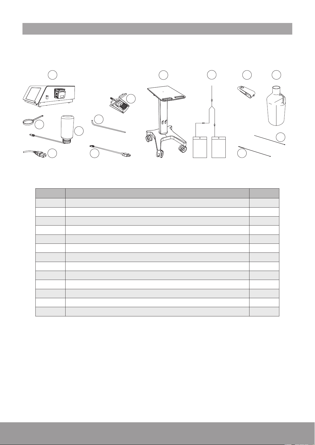
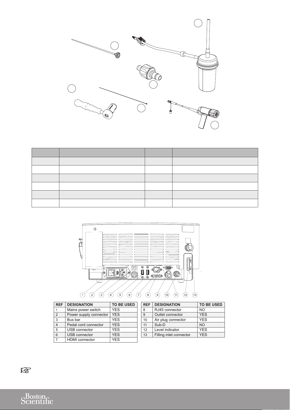
2. COMPONENTS
The components provided for your device will vary, according to your conguration.
1
2
3
4
9
10
6
7
8
11
12
NON STERILE ZONE
REF DESIGNATION QTY
1 Console (with peristaltic pump) or 1
2 Cart - optional 1
3 Fluid management system - optional 1
5
13
4 USB key 1
5 2.5 L Demineralized water 1
6 Stone catcher support 1
7 Cooling system lling kit 1
8 Power cord 1
9 Wired pedal 1
10 Draining tube 1
11 External video cord - optional 1
12 Cleaning brush 1
13 Cleaning rod 1
Figure 1
6
16
1
2
4
3
568
7
119101312
REF
DESIGNATION
TO BE USED
1
Mains power switch
YES
2
Power supply connector
YES
3
Bus bar
YES
4
Pedal cord connector
YES
5
USB connector
YES
6
USB connector
YES
7
HDMI connector
YES
REF
DESIGNATION
TO BE USED
8
RJ45 connector
NO
9
Outlet connector
YES
10
Air plug connector
YES
11
Sub-D
NO
12
Level indicator
YES
13
Filling inlet connector
YES
14
15
18
17
19
STERILE ZONE
REF DESIGNATION QTY STERILE STATE
14 Stone catcher - optional 1 Provided sterile
15 Multiuse torque wrench 1 To be sterilized before use
16 Probe 1 Provided sterile
17 Unclogging rod 2 To be sterilized before use
18 Aspiration plug 1 To be sterilized before use
19 Handpiece 1 To be sterilized before use
Figure 2
Sub-D and RJ-45 (After Sales only).
Figure 3
7
3. INSTALLATION
Please make sure that you have all the required parts
and tools to complete the installation of your device prior
to starting work
Refer to the Packing List.
Follow the instructions in the indicated order.
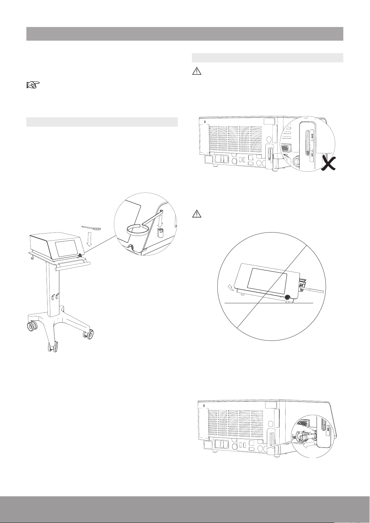
3.1. INSTALLING THE CONSOLE
1. Install the console on a at, stable surface or use the
cart (optional) designed for the console.
2. Remove the protective lm from the console.
3. Install the stone catcher support.
3.2. FILLING THE COOLING SYSTEM
To avoid interruptions during treatment, make sure
that the cooling liquid is above the minimum level
before use. If needed, ll the cooling system as
described below.
Figure 5
Do not tilt the console more than 10 degrees when
there is water in the cooling system.
Figure 6
Figure 4
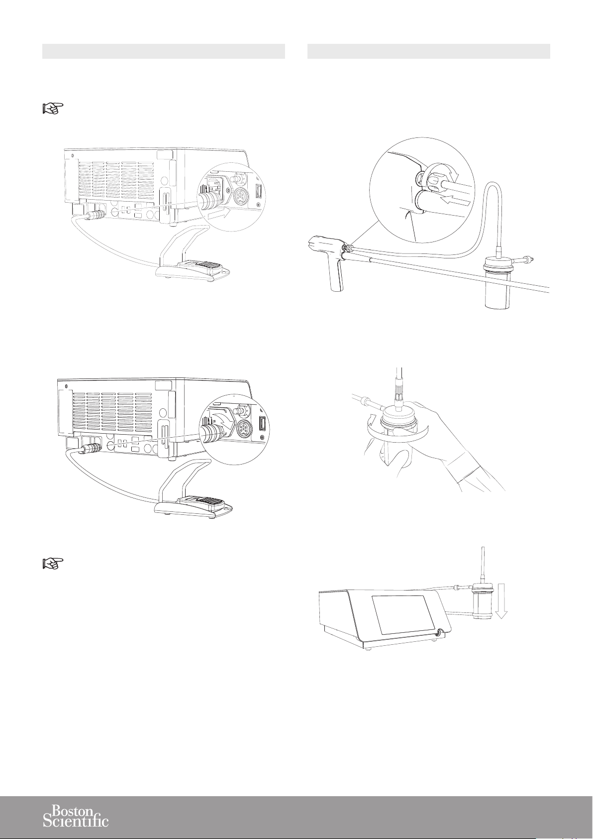
1. To remove the air vent plug, push the grey ring and
pull the air vent simultaneously.
Figure 7
8
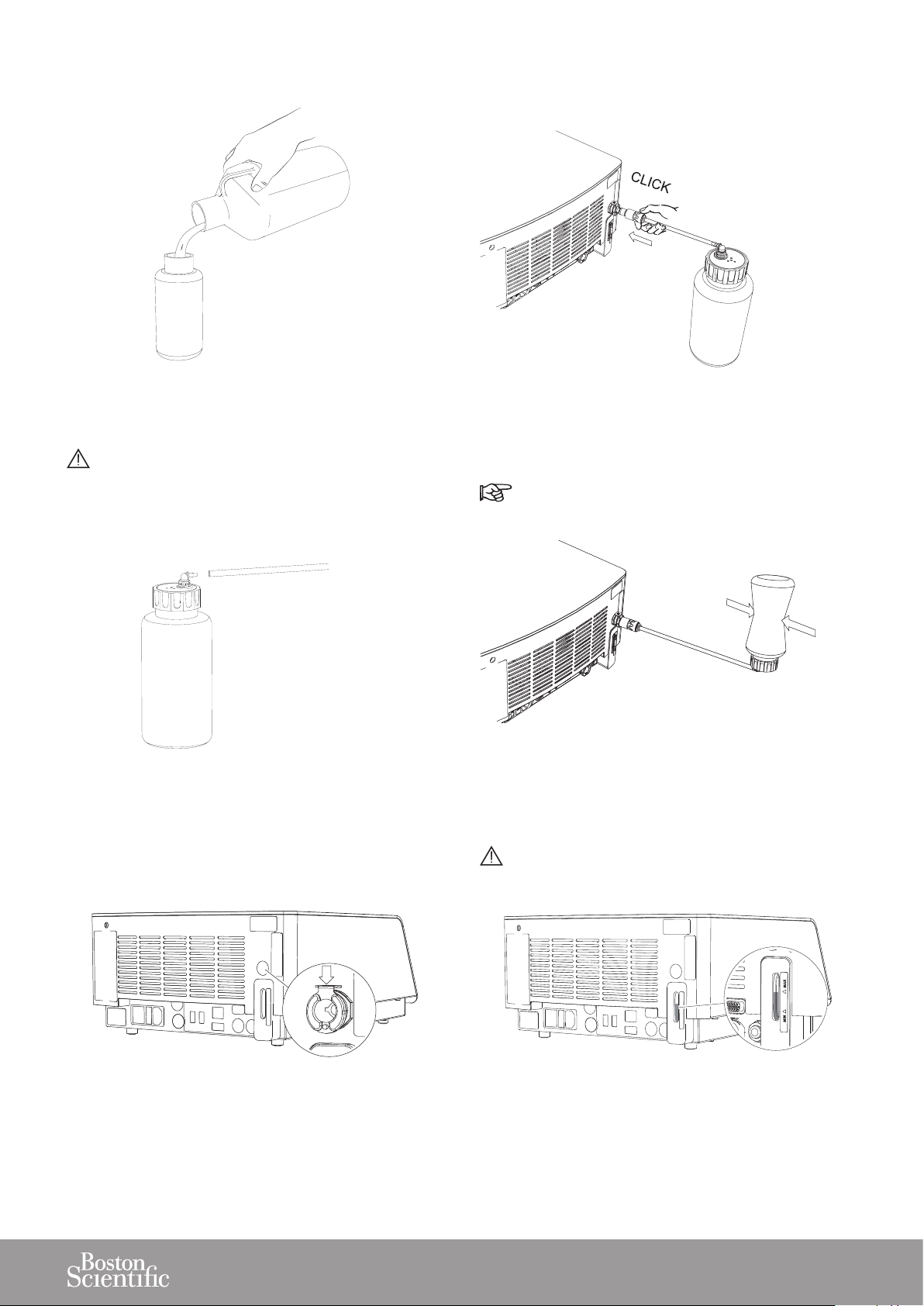
2. Fill the lling bottle and close it.
5. Push the lling tube into the lling inlet connector
until it engages.
Figure 8
Only use demineralized water to ll the cooling
system.
3. Connect the lling tube to the lling bottle.
Figure 9
Figure 11
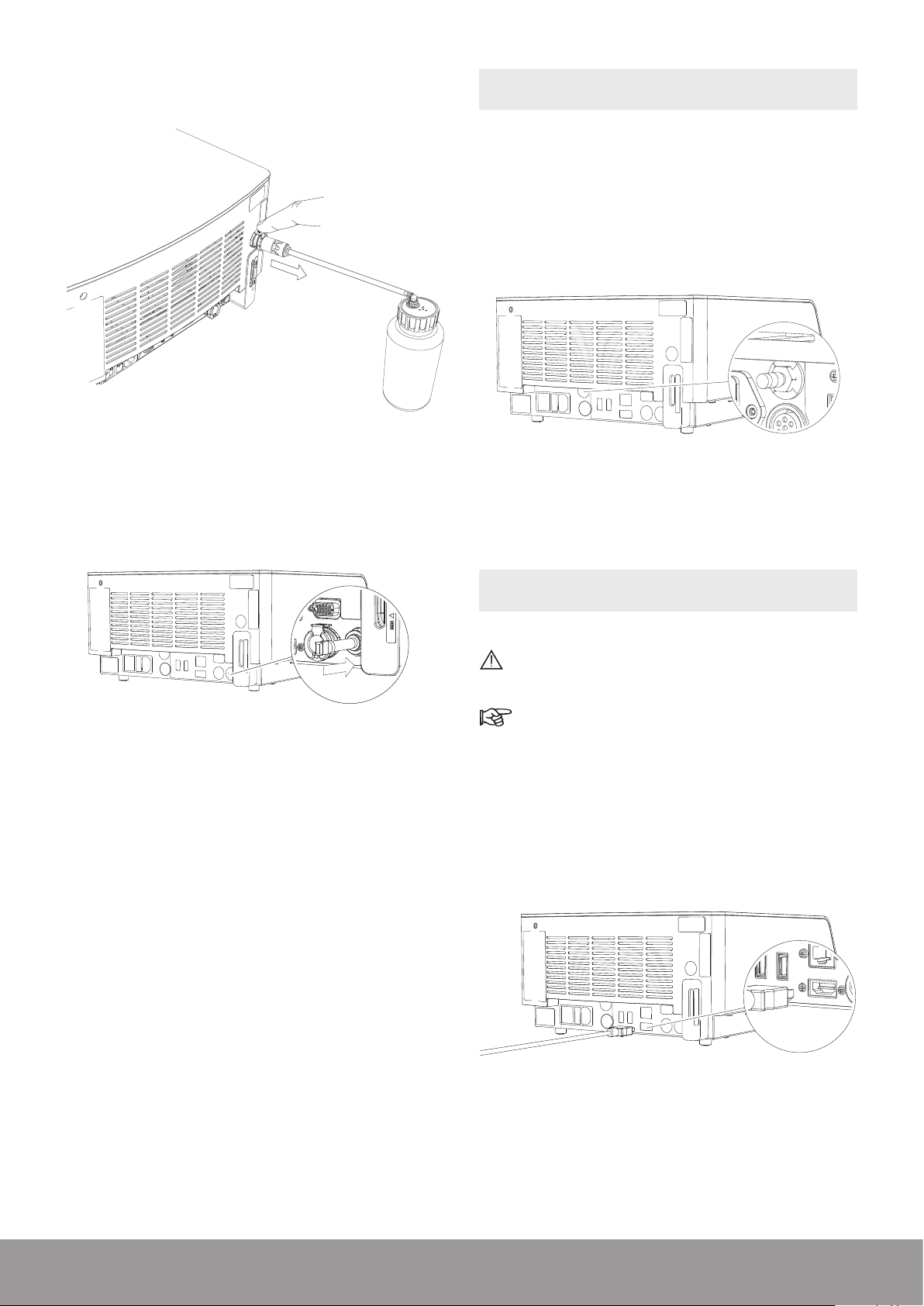
6. Invert the lling bottle and squeeze it to ll the tank.
In case of over-lling, please refer to Emptying
the Cooling Liquid Circuit section.
Figure 12
4. Make sure that the metal locking part is in the down
position.
Figure 10
Make sure that the level of water in the tank is
between the min. and max. indicators.
Figure 13
9
7. Push the metal locking part down to remove the lling
tube.
Figure 14
3.3. CONNECTING THE CONSOLE TO THE
EQUIPOTENTIAL CONDUCTOR
When applicable and according to your in-house protocol,
connect the equipotential conductor at the rear of the
console with the bus bar.
The equipotential conductor provides a connection
between the unit and the potential equalization bus bar
of the electrical installation when necessary.
Figure 16
8. Re-insert the air vent plug up to the stop.
Figure 15
The equipotential cable is not supplied with the console.
3.4. CONNECTING THE VIDEO CORD
(OPTIONAL)
Only connect products compliant with IEC 60950
or equivalent.
The console must be OFF before connecting the
video cord.
1. Connect the video cord to the HDMI connector at
the rear of the console and to a video monitor that
supports “Picture-in-Picture.”
2. Follow the instructions provided for the video monitor
to select the video input.
10
Figure 17
3.5. INSTALLING THE PEDAL
3.6. INSTALLING THE STONE CATCHER
1. Connect the pedal cord to the corresponding connector
at the rear of the console.
Pay attention to the pedal cord connector indexation.
Figure 18
2. Make sure that the pedal cord connector is in the
correct position and screw the securing nut.
Case 1: Use of a sterile, single-use Stone Catcher
(optional)
1. Screw the sterile connector of the stone catcher into
the handpiece.
Figure 20
2. Tighten the Stone Catcher lid.
Figure 19
The pedal can be placed in a protective bag (not
supplied).
3. Make sure that the pedal is in an accessible location
before starting treatment.
Figure 21
3. Insert the stone catcher into the stone catcher support.
Figure 22
11
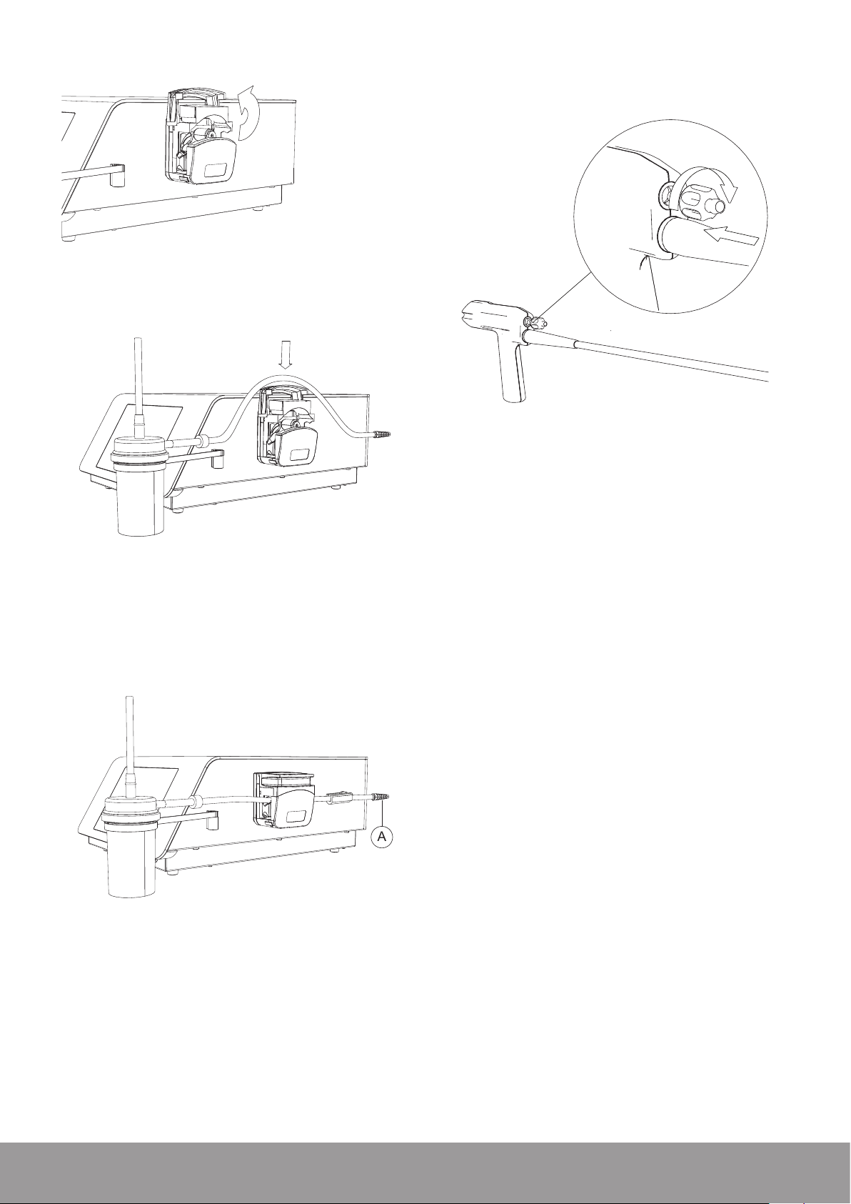
4. Open the pump.
A
Figure 23
5. Place the stone catcher output tube into the pump.
Case 2: Use of an in-house aspiration system.
1. Screw the aspiration plug to the handpiece.
Figure 26
2. Connect the in-house aspiration system on the
aspiration plug.
Figure 24
6. Close the pump.
7. Connect the stone catcher output tube end with the
conical connector (A) to the optional uid management
system or to your uid disposal system.
3. Follow the instructions provided for the in-house
aspiration system.
Figure 25
8. Make sure that the output tube is not twisted or under
tension when placed in the peristaltic pump device
head.
12
3.7. INSTALLING THE SINGLE-USE FLUID
MANAGEMENT SYSTEM SET (OPTIONAL) AND
REPLACEMENT POUCH
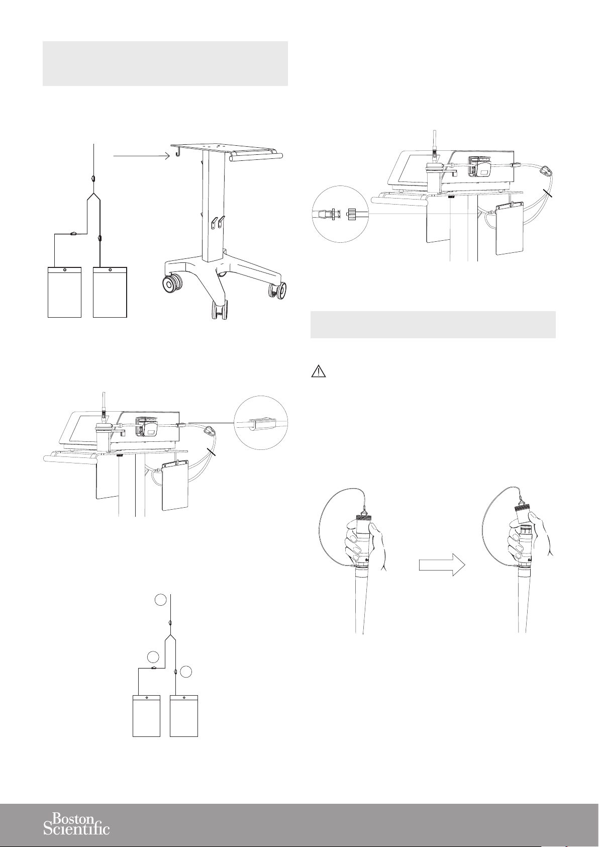
1. Suspend the two uid pouches, on the cart or on an
IV pole, at a level that is lower than the console.
Figure 27
4. When the open pouch is lled, open the closed clamp
(B) rst.
5. Close the open clamp (C) (adjacent to the lled pouch).
6. The lled pouch can be exchanged for a new empty
pouch, using the Luer-lock connection.
Figure 30
3.8. CONNECTING THE STERILIZED HANDPIECE
TO THE CONSOLE
2. Connect the uid management system input tube (A)
to the stone catcher output tube connector.
Figure 28
3. Close clamp (B) of one pouch to ll the rst pouch.
Clamp (C) stays open.
A
Make sure that the handpiece connector is dry before connecting it to the console.
1. To remove the protective cap from the handpiece cord,
hold the metal part of the handpiece cable connector
and push up on the cap using your thumb and index
nger.
C
Figure 29
Figure 31
B
13
2. Remove the protective cap from the console.
Figure 32
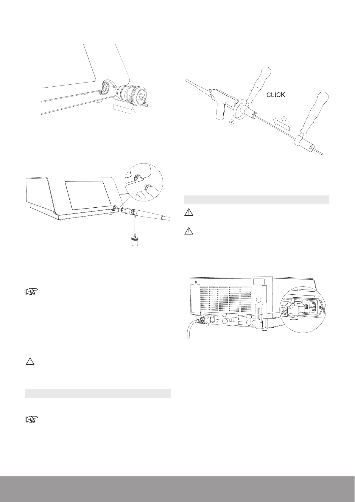
3. Connect the handpiece to the console.
2. Use the wrench to rmly tighten the appropriate probe
on the handpiece.
Multiuse Torque wrench
Figure 34
3.10. CONNECTING THE POWER CORD
Figure 33
4. Pay attention to the orientation of the handpiece
connector.
The red dot must be on top for proper alignment.
5. Make sure that the handpiece cord does not touch
the oor and is not compressed or squeezed in any
way that might impede circulation of the cooling liquid.
6. The handpiece connection to the console is maintained
by a mechanical lock. During use, the lock icon (orange
handpiece activation icon) remains illuminated.
Do not exceed the maximum number of usage
cycles for the handpiece as specied in the
Technical Data section.
Connect only to a FI protected mains power supply
(FI = Residual current protection).
To prevent damage to the console, make sure that
its rated voltage meets the local line voltage.
Connect the power cord to the power socket at the rear
of the console.
Figure 35
3.9. INSTALLING A PROBE ON THE HANDPIECE
1. Select the appropriate probe.
Refer to the Probe Compatibility Table section.
14
4. GETTING STARTED
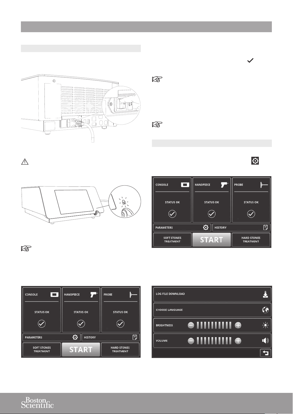
4.1. STARTING THE DEVICE
1. Use the mains power switch located on the rear panel
to switch on the console.
Figure 36
Do not disconnect the handpiece while the lock
icon is switched on (in orange), since this may
result in damage.
3. The console automatically performs a series of
diagnostic tests.
4. The console displays a green check mark for each
successfully completed diagnostic test.
In case of error messages, refer to the troubleshooting information provided on the screen or to the
Troubleshooting section.
5. The console is ready for use when all diagnostic tests
have been successfully completed.
The touch screen can be operated when wearing
surgical gloves.
4.2. ADJUSTING THE PARAMETERS
1. To access the PARAMETERS screen from the
STAND BY screen, press PARAMETERS .
Figure 37
When the handpiece is connected when starting
the device, the lock icon will be orange and the
purge will start.
2. Wait until the STAND BY screen appears.
Figure 38
Figure 39
2. Congure the parameters as needed.
Figure 40
15
 Loading...