

Page 1
POWER
FAULT
ISOLATOR
ACTIVE
F
usion
Loop Module
Loop Module
Installation Guide
©2014 EMS Radio Fire & Security Systems Ltd. All rights reserved 1/2 TSD077 Iss 3c 15/04/14 AJM
FCX-532-001
FCX-532-002
Fusion Loop Module
Fusion Loop Module c/w Remote Aerial Facility
POWER
FAULT
ISOLATOR
ACTIVE
F usion
F usion
Loop Module
Part No Product Description
Step 1 Pre Installation
!
The Fusion Loop Module installation must conform to
applicable local installation codes and
should only be
installed by a fully trained competent person.
The following points require consideration upon installation:
Loop Module location. Refer to the design drawings generated
from the radio survey.
Radio performance. Refer to step 3 to ensure the radio
performance is optimised.
Remote aerials.
If using remote aerials with this product, refer
to the Remote Aerial Installation manual for more information.
A maximum of 5 Loop Modules can be connected per loop.
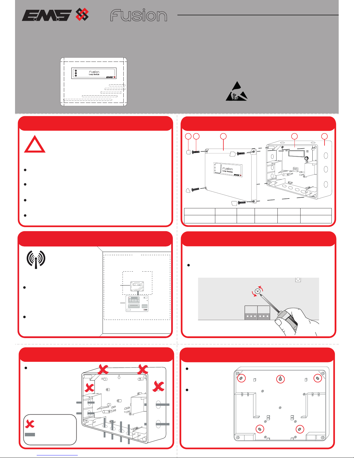
Step 2 Loop Module Components
1
2 3
4
5
4X Corner
covers
4x Lid
Screws
1x Loop
Module Lid
1x Loop
Module PCB
1x Loop Module
Back Box
Part Description
Item No
1 2 3 4
5
FIRE
Fire Alarm Control
Step 3 Mounting Location Guidelines
Ensure the Loop Module is
not installed within 2m of
other radio or electrical
equipment (not including
the Control Panel).
Ensure the Loop Modules
aerials are not installed
within 0.6m of any metal
work.
POWER
FAULT
0.6m
To ensure the
optimum range
performance of
the Loop Module
is achieved, the following
should be considered:
2m
Control
Panel
Loop
Module
Step 4 PCB Removal
The internal PCB of the Loop Module can be removed to ensure that
damage is not caused during installation.
Remove the central retaining screw prior to unclipping the PCB.
WD
BACK
0V
RX
TX
3V
SCR
+
-
LOOP IN
SCR
LOOP OUT
+
-
Fit the Back Box
to the wall.
All five circled
fixing positions
are available for
use.
Step 6 Fit Loop Module Back Box to the Wall
Step 5 Prepare the Loop Module Back Box
Drill the required
cable entry points
where necessary.
= Do Not Use
= Available Cable
Entry Points
ATTENTION
OBSERVE PRECAUTIONS
FOR HANDLING
ELECTROSTATIC
SENSITIVE
Page 2
Specification
Operating
Temperature -10°C to 50°C (ambient)
Storage
Temperature 0°C to 35°C
Humidity Up to 95% non-condensing
Operating
Voltage 17 to 28V DC
Power
Requirements 17mA @24V DC
IP Rating IP54
Operating
Frequency 868MHz
Output
Transmitter
Power Variable 0 - 14 dBm
Dimensions 270mm (W) 205mm (H) 75mm (D)
Weight 0.95kg
Location Type A: For indoor use
EMS. Technology House, Herne Bay, Kent, CT6 8JZ, United Kingdom
Manufacturer
Year of
manufacture See devices serial number label
2002/96/EC (WEEE directive):
Products marked with this symbol cannot be disposed of as unsorted
municipal waste in the European Union. For proper recycling, return this
product to your local supplier upon purchase of equivalent new
equipment, or dispose of it at designated collection points. For more
information see www.recyclethis.info
Contact Information
EMS. Technology House, Herne Bay, Kent, CT6 8JZ, United Kingdom
t: +44 (0) 1227 369570
f: +44 (0) 1227 369679
e: enquiries@emsgroup.co.uk
www.emsgroup.co.uk
Regulatory Information
EMS General
European Union
directives
1999/5/EC (R&TTE directive):
Hereby EMS Radio Fire & Security Systems declares that this device is in
compliance with the essential requirements and other relevant provisions
of Directive 1999/5/EC.
Approved to
EN54-17:2005
EN54-18:2005
E
N54-25:2008
©2014 EMS Radio Fire & Security Systems Ltd. All rights reserved 2/2 TSD077 Iss 3c 15/04/14 AJM
Certification
Certification
body 0359
CPR Certificate 0359-CPR-0222
Step 10 Reassemble the Loop Module
Ensure that the Loop Module PCB is correctly inserted and the
PCB retaining screw is refitted.
Refit the Loop Module lid, ensuring all four lid screws and
corner covers are fitted.
POWER
FAULT
ISOLATOR
ACTIVE
Care must be taken to ensure the LEDs are not damaged by
the light pipe when refitting the Loop Module Lid.
F usion
Loop Module
Loop Module 1
Loop Module 2
Loop Module 3
Loop
In
Loop
Out
+
-
Control
Panel
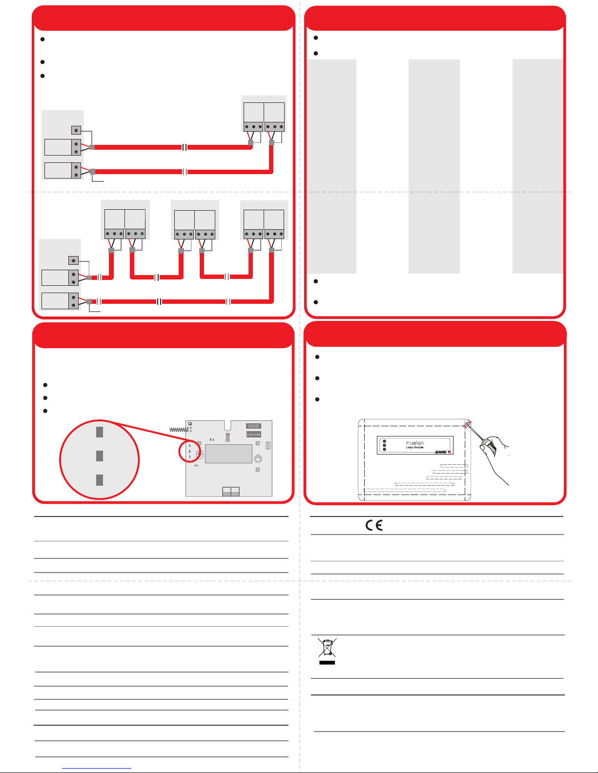
Step 7 Connection Wiring
Multiple Loop Modules (max 5)
Loop Module 1
Single Loop Module
+
-
Screen
Scr
LoopInLoop
Out
Scr
+-+
-
Scr
LoopInLoop
Out
Scr
+-+
-
Scr
LoopInLoop
Out
Scr
+-+
-
Scr
LoopInLoop
Out
Scr
+-+
-
Loop cables should only be passed via the access points
available.
Flame retardant cable glands must be used.
Cable lengths should be kept to a minimum to ensure cables are
away from the PCBs aerials.
RX
RF1 RF2
Step 9 Applying Power
Apply power to the Control Panel. The normal LED states for the
Loop Module are as below:
Healthy LED - Green LED will be on.
Fault LED - Yellow LED will be off.
Sys Fault LED - Yellow LED will be off.
TX
RADIO
WD
RESET
HELP
RX
ON
1 2 3 4 5 67 8
BACK
POWER
FAULT
ISOLATE
0V
RX
TX
3V
SCR
+
-
LOOP IN
SCR
LOOP OUT
+
-
1 2 3 4 5 6 7
POWER
FAU LT
ISOLATE
addr
DIL
switch
setting
1…….…8
addr
DIL
switch
setting
1…….…8
addr
DIL
switch
setting
1…….…8
addr
DIL
switch
setting
1…….…8
addr
DIL
switch
setting
1…….…8
1 10000000 11 11010000 21 10101000 31 11111000 41 10010100
2 01000000 12 00110000 22 01101000 32 00000100 42 01010100
3 11000000 13 10110000 23 11101000 33 10000100 43 11010100
4 00100000 14 01110000 24 00011000 34 01000100 44 00110100
5 10100000 15 11110000 25 10011000 35 11000100 45 10110100
6 01100000 16 00001000 26 01011000 36 00100100 46 01110100
7 11100000 17 10001000 27 11011000 37 10100100 47 11110100
8 00010000 18 01001000 28 00111000 38 01100100 48 00001100
9 10010000 19 11001000 29 10111000 39 11100100 49 10001100
10 01010000 20 00101000 30 01111000 40 00010100 50 01001100
51 11001100 61 10111100 71 11100010 81 10001010 91 11011010
52 00101100 62 01111100 72 00010010 82 01001010 92 00111010
53 10101100 63 11111100 73 10010010 83 11001010 93 10111010
54 01101100 64 00000010 74 01010010 84 00101010 94 01111010
55 11101100 65 10000010 75 11010010 85 10101010 95 11111010
56 00011100 66 01000010 76 00110010 86 01101010 96 00000110
57 10011100 67 11000010 77 10110010 87 11101010 97 10000110
58 01011100 68 00100010 78 01110010 88 00011010 98 01000110
59 11011100 69 10100010 79 11110010 89 10011010 99 11000110
60 00111100 70 01100010 80 00001010 90 01011010 100 00100110
101 10100110 106 01010110 111 11110110 116 00101110 121 10011110
102 01100110 107 11010110 112 00001110 117 10101110 122 01011110
103 11100110 108 00110110 113 10001110 118 01101110 123 11011110
104 00010110 109 10110110 114 01001110 119 11101110 124 00111110
105 10010110 110 01110110 115 11001110 120 00011110 125 10111110
126 01111110
Step 8 Configuration
The address number is set using the onboard 8 way switch.
Available selections are shown in the table below.
The Loop Modules programming is configured using the Loop
Modules menu structure.
Refer to the Engineers Guide (Doc Ref: TSD062) for full
programming details.
Loop
In
Loop
Out
+
-
Control
Panel
+
-
Screen
Screen Not Connected
Screen Not Connected
 Loading...