

Page 1
System 5000
Step-By-Step Guide (MK1)
Page 2

EMS 5000 FIREPOINT
Table Of Contents
Section Page No
1. HOW TO RESET FIRE & FAULT EVENTS ....................................................... 4
2. HOW TO ENTER THE SYSTEM EVENT LOG ................................................... 4
3. HOW TO ENTER THE SYSTEM EVENT LOG WITH FAULTS DISPLAYED .............. 5
4. HOW TO ISOLATE DEVICES ...................................................................... 7
5. HOW TO RE-INSTATE DEVICES FROM ISOLATION ........................................ 8
6. HOW TO ISOLATE A DEVICE ACROSS A NETWORK SYSTEM ........................... 9
7. HOW TO RE-INSTATE AN ISOLATED DEVICE ACROSS A NETWORK ................ 11
8. HOW TO LOG ON A DEVICE ..................................................................... 13
9. HOW TO REMOVE A DEVICE ..................................................................... 16
10. HOW TO REPLACE DEVICES ................................................................... 17
11. HOW TO PUT ZONES INTO TEST (TESTING DEVICES) ................................ 20
12. HOW TO TAKE ZONES OUT OF TEST ........................................................ 22
13. HOW TO PUT ALL THE ZONES INTO TEST ACROSS A NETWORK .................. 24
14. HOW TO TAKE ALL THE ZONES OUT OF TEST ACROSS A NETWORK ............. 25
15. HOW TO TEST INDIVIDUAL SOUNDERS ................................................... 27
16. FAULT LIST .......................................................................................... 31
17. DO’S AND DON’TS ................................................................................ 33
©2015 EMS Security Group Ltd. All rights reserved. TSD258 Iss 3 25/06/15 AJM
2
Page 3
EMS 5000 FIREPOINT
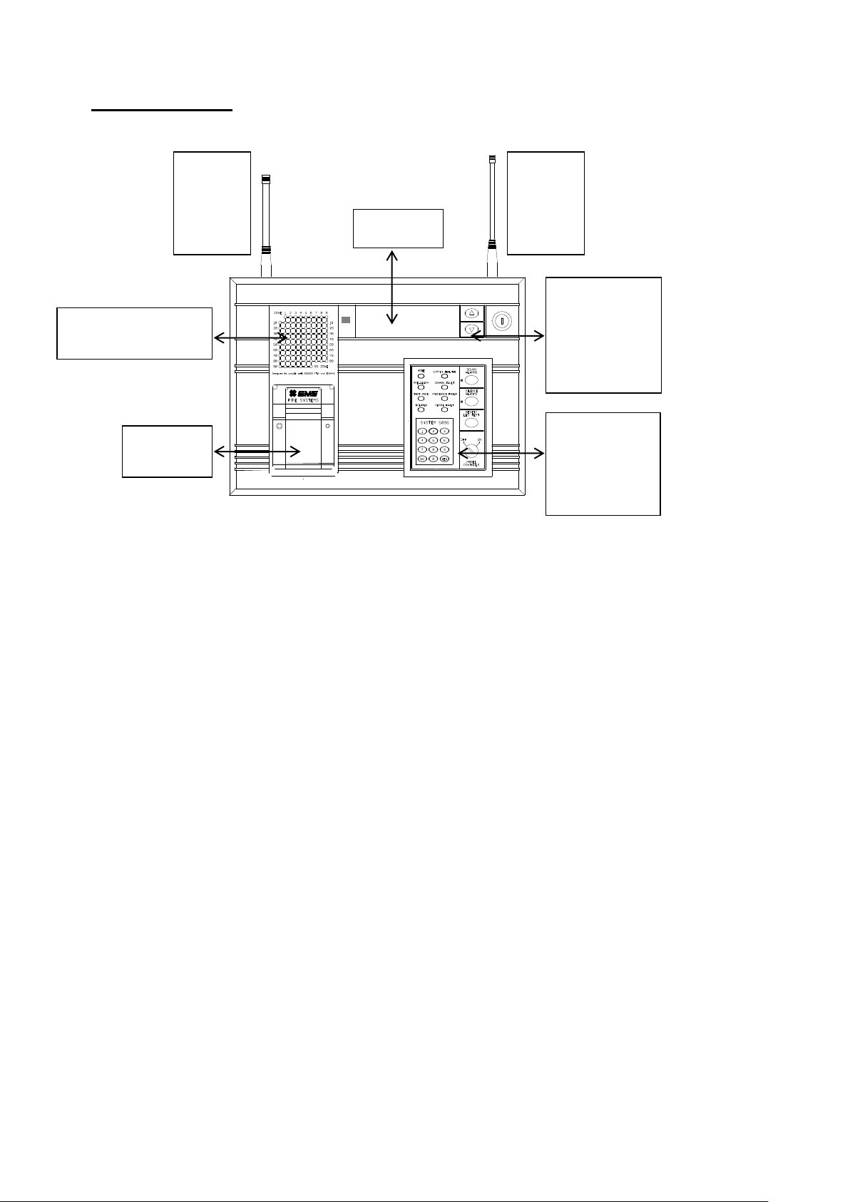
Zoned Led For
Fire Indication
Thermal
Printer
VHF
Helical
Aerial
(R/x)
UHF
Helical
Aerial
(T/x)
Display
Arrows
For
Scrolling
Up & Down
The Menus
Keypad &
Panel
Control
Keyswitch
5000 FirePoint
©2015 EMS Security Group Ltd. All rights reserved. TSD258 Iss 3 25/06/15 AJM
3
Page 4
EMS 5000 FIREPOINT
01 FIRE ALARM TOT 01
RADIO CALLPOINT
ZONE 01 DEVICE005
Alarms Silenced
Push Any Key
Device RESET:
RADIO CALLPOINT
Push Any Key
Status Normal
Date Time
Panel in Access
|***Options ****|
>Passwords <
|Time and Date |
Yes =Select Time
|Time and Date |
>Logging <
|Fire System Opts |
YES = Select Time
|**Event Logging *|
>View Log At Date <
|View Entire Log |
Yes = Select Time
1. How To Reset Fire & Fault Events
To reset fires/faults on the 5000 FirePoint, Insert the key into the panel
controls keyswitch, located at the right of the panel. Turn the panel control key
to the on position.
Step Action Screen Display
No
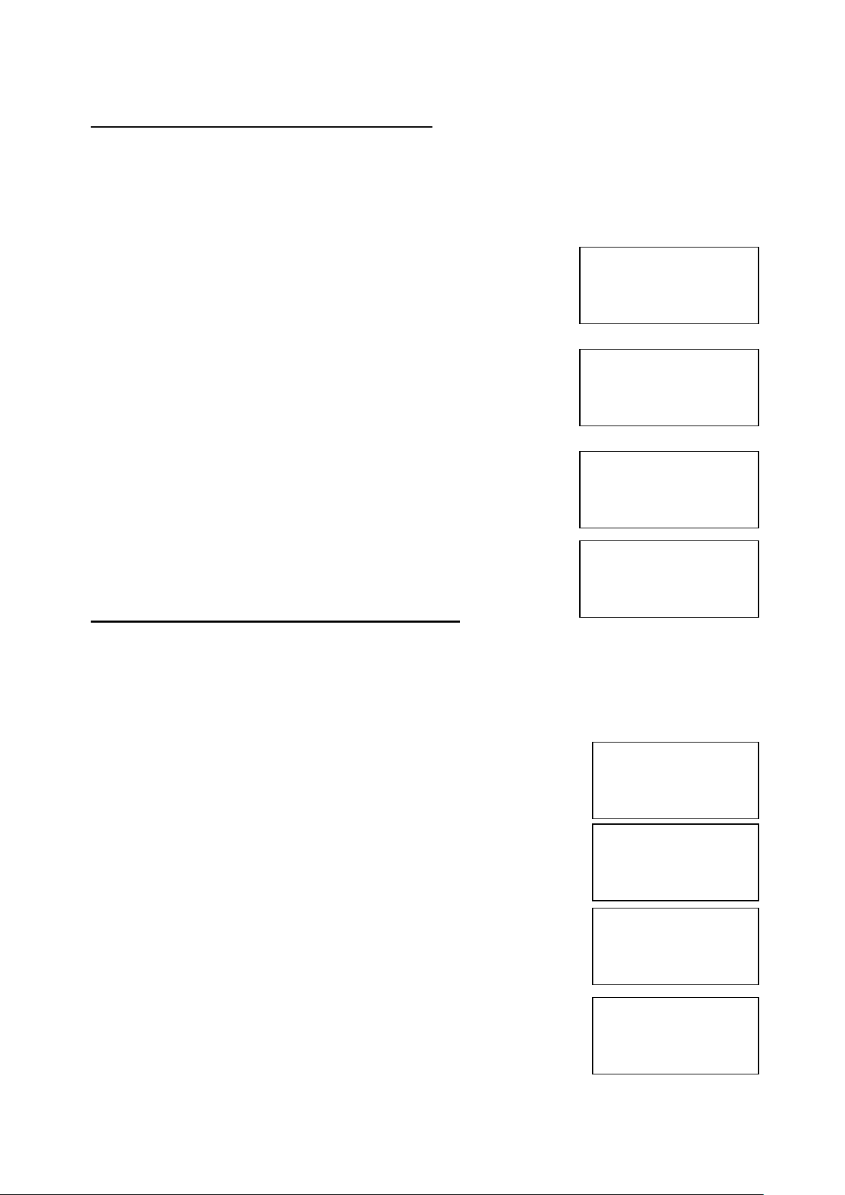
1 This a normal fire event
2 Press the Silence Alarm button and the
screen will now briefly display: (Press Any
Key)
3 Press the Reset/Led Test button and the
screen will now briefly display: (Press
Any Key)
4 The event is now clear, turn the key to the off
position
2. How To Enter The System Event Log
To enter the System event log on the 5000 FirePoint, insert the key into the
panel controls keyswitch, located at the right of the panel.
Step Action Screen Display
No
1 Turn the key to the on position and the screen
will display:
2 Press 0 key and the screen will now display:
3 Press key two times and the screen will
display:
4 Press Yes key and the screen will now
display:
©2015 EMS Security Group Ltd. All rights reserved. TSD258 Iss 3 25/06/15 AJM
4
Page 5

EMS 5000 FIREPOINT
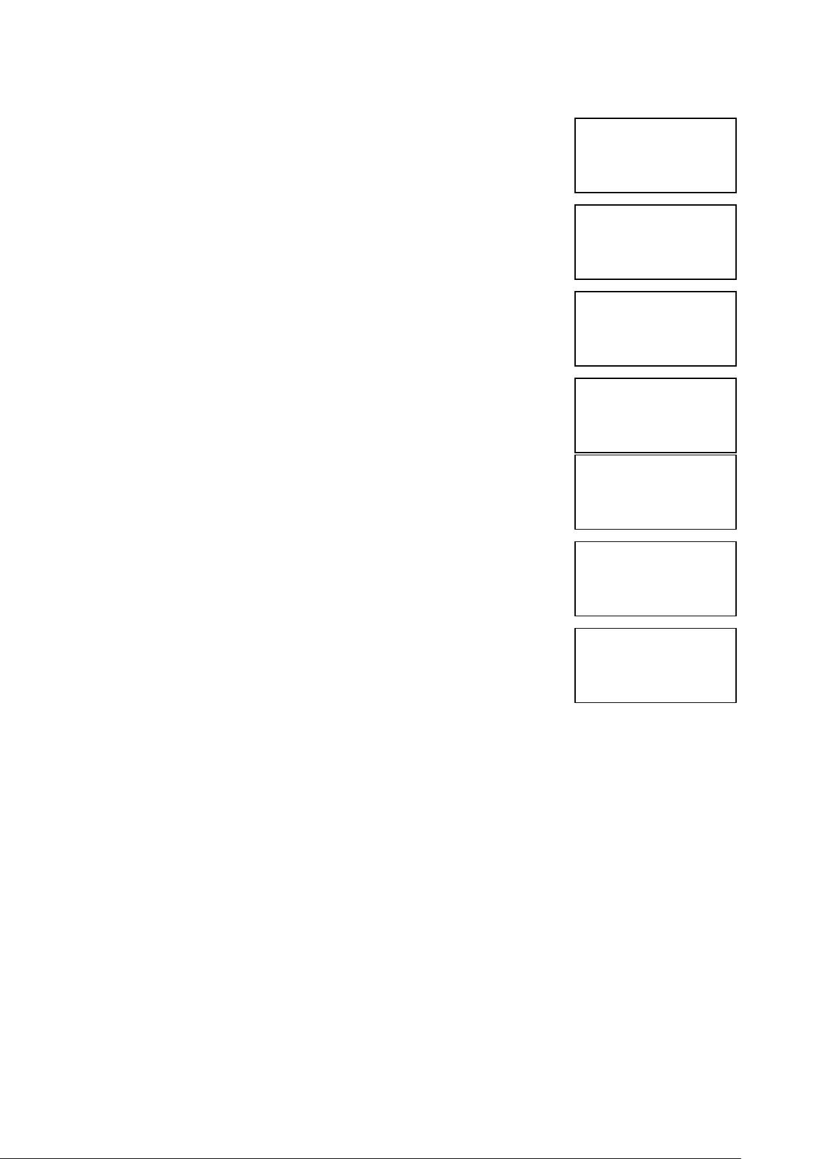
Enter the date to
View: / /
Yes = Finish Time
- - - - - - - - - - - - - - - On 28/05/03 At 00:00
New Day of 28/05/03
Yes = Select Time
|** Fire system **|
>Dev. Isolate/Test<
| Net. Isolate/Test |
Yes= Select Time
|Brigade Isolate |
>Engineers Config<
|Printer Options |
Yes= Select Time
Enter Your PIN
For Access>
Then Press YES
Time
|** Eng.; Config ** |
>Device Database <
|Sounder Options |
Yes= Select Time
Panel in Access
Date Time
5 Press Yes key and the screen will now
display:
6 Enter the date Required to be viewed in
dd/mm/yy Format, (e.g.28/05/03) then press
Yes key and the screen will now display:
The log for the date selected can now be viewed by using the
Arrows next to the display, all fire and fault events are listed in date
and time order. Using number 5 on the keypad will take you to the
oldest event, number 8 on the keypad latest event. (Look at the fault
list for examples of descriptions that are in the log).
3. How To Enter The System Event Log With Faults Displayed
To enter the sytem event log on the 5000 FirePoint with faults displayed there
are two ways.
The first way is to isolate the devices that are in fault. The second way is to
enter the engineer’s menu main. To enter the engineer’s main menu insert the
key into the panel controls keyswitch, located at the right of the panel.
Step Action Screen Display
No
1 Turn the key to the on position and the
screen will display:
2 Press 0 key and the screen will now display:
3 Press key four times and the screen will
display:
4 Press Yes key and the screen will now display:
5 Press 221100 then press Yes key and the
screen will display:
©2015 EMS Security Group Ltd. All rights reserved. TSD258 Iss 3 25/06/15 AJM
5
Page 6
EMS 5000 FIREPOINT
|Reset System |
>Lan Options <
|^^^^^^^^^^^^^^|
Yes= Select Time
|Reset Security |
>Reset System <
|Lan Options |
Yes= Select Time
|** Main Menu **|
>Pins & Access <
|System Support |
Yes= Select Time
|Output Setup |
>Logging <
|Remote Rxers |
Yes= Select Time
Enter the date to
View: / /
Yes = Finish Time
- - - - - - - - - - - - - - - On 28/05/03 At 00:00
New Day of 28/05/03
Yes = Select Time
|**Event Logging *|
>View Log At Date <
|View Entire Log |
Yes = Select Time
6 Press Number 8 on the keypad and the screen
will now display: (number 8 is a quick move key
that take you to the bottom of the menu)
7 Press key once and the screen will now
display:
8 Press Yes key followed 0 key on the keypad the
screen will now display:
9 Press key seven times and the screen will
display:
10 Press Yes key and the screen will now
display:
11 Press Yes key and the screen will now
display:
12 Enter the date Required to be viewed in
dd/mm/yy Format, (e.g.28/05/03) then press
Yes key and the screen will now display:
The log for the date selected can now be viewed by using the
Arrows next to the display, all fire and fault events are listed in date
and time order. Using number 5 on the keypad will take you to the
oldest event, number 8 on the keypad latest event. (Look at the fault
list for examples of descriptions that are in the log).
©2015 EMS Security Group Ltd. All rights reserved. TSD258 Iss 3 25/06/15 AJM
6
Page 7
EMS 5000 FIREPOINT
|***Options ****|
>Passwords <
|Time and Date |
Yes =Select Time
|Logging |
>Fire System Opts<
|Remote Access |
|** Fire system **|
>Dev. Isolate/Test<
| Net. Isolate/Test |
Yes= Select Time
|** Device Status * |
>Number is: 001 <
|Status is: ACTIVE|
Yes= Select Time
Enter Device
(Number 1-256)
Number > _
Yes = Finish Time
|** Device Status * |
>Number is: 125 <
|Status is: ACTIVE|
Yes= Select Time
|Number is: 125 |
>Status is: ACTIVE<
| Zone is : 01 |
Yes= Select Time
|Number is: 125 |
>Status is :ISOLATE<
| Zone is : 01 |
Yes= Select Time
Panel in Access
Date Time
Panel in Access
Date Time
4. How To Isolate Devices
To isolate a device on the 5000 FirePoint, Insert the key into the panel controls
keyswitch, located at the right of the panel.
Step Action Screen Display
No
1 Turn the key to the on position and the
screen will display:
2 Press 0 key and the screen will now display:
3 Press key three times and the screen will
display:
4 Press Yes key and the screen will now
display:
5 Press Yes key and the screen will now
display:
6 Press 0 key and the screen will now
display:
7 Enter the device number that you want to
isolate (e.g. 125) then press Yes key and the
screen will now display:
8 Press key one time and the screen will
display:
9 Press Yes key and the screen will now
display:
10 Press No key three times and the screen will
now display:
©2015 EMS Security Group Ltd. All rights reserved. TSD258 Iss 3 25/06/15 AJM
7
Page 8

EMS 5000 FIREPOINT
Status Normal
Date Time
|***Options ****|
>Passwords <
|Time and Date |
Yes =Select Time
|Logging |
>Fire System Opts<
|Remote Access |
Yes = select Time
|** Fire system **|
>Dev. Isolate/Test<
| Net. Isolate/Test |
Yes= Select Time
| ** Device Status * |
>Number is: 001 <
|Status is: ACTIVE|
Yes= Select Time
Enter Device
(Number 1-256)
Number > _
Yes = Finish Time
| ** Device Status * |
>Number is: 125 <
|Status is: ISOLATE|
Yes= Select Time
Panel in Access
Date Time
11 Turn the Control key switch to the off position
and the screen will now display:
Note: The isolate LED on the 5000 FirePoint panel will illuminate with
an intermittent beep to show there is an isolation on the system.
5. How To Re-instate Devices From Isolation
To reactivate a device on the 5000 FirePoint, insert the key into the panel
controls keyswitch, located at the right of the panel. Turn the key to the on
position.
Step Action Screen Display
No
1 Turn the key to the on position and the
screen will display:
2 Press 0 key and the screen will now display:
3 Press key three times and the screen will
display:
4 Press Yes key and the screen will now
display:
5 Press Yes key and the screen will now
display:
6 Press 0 key and the screen will now display:
7 Enter the device number that you want to
isolate (e.g. 125) then press Yes key and the
screen will now display:
©2015 EMS Security Group Ltd. All rights reserved. TSD258 Iss 3 25/06/15 AJM
8
Page 9
EMS 5000 FIREPOINT
|Number is: 125 |
>Status is: ISOLATE<
| Zone is : 01 |
Yes= Select Time
|Number is: 125 |
>Status is : ACTIVE <
| Zone is : 01 |
Yes= Select Time
Panel in Access
Status Normal
|***Options ****|
>Passwords <
|Time and Date |
Yes =Select Time
|Logging |
>Fire System Opts<
|Remote Access |
Yes = select Time
|** Fire system **|
>Dev. Isolate/Test<
| Net. Isolate/Test |
Yes= Select Time
|Dev. Isolate/Test |
>Net. Isolate/Test <
|Zone Isolate/Test |
Yes= Select Time
Panel in Access
Date Time
8 Press key one time and the screen will
display:
9 Press Yes key twice and the screen will now
display:
10 Press No key three times and the screen will
now display:
11 Turn the Control key switch to the off
Position and the screen will now display:
Note: The isolate LED on the 5000 FirePoint Panel will clear and the
isolate beep will stop.
6. How To Isolate A Device Across A Network System
To isolate a device across the network on the 5000 FirePoint, insert the key
into the panel controls keyswitch, located at the right of the panel.
Step Action Screen Display
No
1 Turn the key to the on position and the
screen will display:
2 Press 0 key and the screen will now display:
3 Press key three times and the screen will
display:
4 Press Yes key and the screen will now
display:
5 Press key one time and the screen will
display:
©2015 EMS Security Group Ltd. All rights reserved. TSD258 Iss 3 25/06/15 AJM
9
Page 10
EMS 5000 FIREPOINT
|* Network Status * |
>Panel Type : PAN <
|Panel : 00 |
Yes= Select Time
|* Network Status * |
>Panel Type : NET <
|Panel : 00 |
Yes= Select Time
|Panel Type : NET |
>Panel : 00 <
|Device : 00 |
Yes= Select Time
|Panel Type : NET |
>Panel : 04 <
|Device : 00 |
Yes= Select Time
|Panel : 04 |
>Device : 00 <
|Status : Active
Yes= Select Time
Enter Device
(Number 1-256)
Number > _
Yes = Finish Time
|Panel : 04 |
>Device : 125 <
|Status : Active
Yes= Select Time
|Device : 125 |
>Status : Active<
|Transmit Event |
Yes= Select Time
|Device : 125 |
>Status : Isolate<
|Transmit Event |
Yes= Select Time
|Status : Isolate |
>Transmit Event <
|^^^^^^^^^^^^^^|
Yes= Select Time
Device 125 on NET 04
Set to ISOLATED
Push Any Key Time
6 Press Yes key and the screen will now
display: (move on to step 8 if H/W)
7 Press Yes key once the Screen will
now display:
NOTE : PAN is for a Hardwired based System.
NET is for a Radio LAN based system.
8 Press key one time and the screen will
display:
9 Press the Yes key to change the panel
number until the required panel number is
shown: (e.g. 04)
10 Press key one time and the screen will
display:
11 Press 0 key and the screen will now
Display:
12 Enter the device number that you want to
isolate (e.g. 125) then press Yes key and
screen will now display:
13 Press key one time and the screen will
display:
14 Press Yes key once the Screen will
now display:
15 Press key one time and the screen will
display:
16 Press Yes key once the Screen will now display:
©2015 EMS Security Group Ltd. All rights reserved. TSD258 Iss 3 25/06/15 AJM
10
Page 11
EMS 5000 FIREPOINT
Panel in Access
Date Time
Status Normal
Date Time
|***Options ****|
>Passwords <
|Time and Date |
Yes =Select Time
|Logging |
>Fire System Opts<
|Remote Access |
|** Fire system **|
>Dev. Isolate/Test<
| Net. Isolate/Test |
Yes= Select Time
|Dev. Isolate/Test |
>Net. Isolate/Test <
|Zone Isolate/Test |
Yes= Select Time
Panel in Access
17 Press NO key three times and the screen will
display:
18 Turn the Control key switch to the off
position and the screen will now display:
Note: The isolate LED on the 5000 FirePoint Master Panel and the 5000
FirePoint Slave Panel 04 will illuminate with intermittent beep to show
there is an isolation on the system.
7. How To Re-instate an Isolated Device Across A Network
To re-instate an isolated device across the network on the 5000 FirePoint,
Insert the key into the panel controls keyswitch, located at the right of the
panel.
Step Action Screen Display
No
1 Turn the key to the on position and the
screen will display:
2 Press 0 key and the screen will now display:
3 Press key three times and the screen will
display:
4 Press Yes key and the screen will now
display:
5 Press key one time and the screen will
display:
©2015 EMS Security Group Ltd. All rights reserved. TSD258 Iss 3 25/06/15 AJM
11
Page 12

EMS 5000 FIREPOINT
|* Network Status * |
>Panel Type : PAN <
|Panel : 00 |
Yes= Select Time
|* Network Status * |
>Panel Type : NET <
|Panel : 00 |
Yes= Select Time
|Panel Type : NET |
>Panel : 00 <
|Device : 00 |
Yes= Select Time
|Panel Type : NET |
>Panel : 04 <
|Device : 00 |
Yes= Select Time
|Panel : 04 |
>Device : 00 <
|Status : Isolate|
Yes= Select Time
Enter Device
(Number 1-256)
Number > _
Yes = Finish Time
|Panel : 04 |
>Device : 125 <
|Status : Isolate|
Yes= Select Time
|Device : 125 |
>Status : Isolate <
|Transmit Event |
Yes= Select Time
|Device : 125 |
>Status : Active<
|Transmit Event |
Yes= Select Time
|Status : Active |
>Transmit Event <
|^^^^^^^^^^^^^^|
Yes= Select Time
6 Press Yes key and the screen will now
display: (move on to step 8 if H/W)
7 Press Yes key once the Screen will
now display
NOTE : PAN is for a Hardwired based System.
NET is for a Radio LAN based system.
8 Press key one time and the screen will
display:
9 Press the Yes key to change the panel
number until the required panel number is
shown: (e.g. 04)
10 Press key one time and the screen will
display:
11 Press 0 key and the screen will now
display:
12 Enter the device number that you want to re-
instate (e.g. 125) then press Yes key and
screen will now display:
13 Press key one time and the screen will
display:
14 Press Yes key once the Screen will
now display:
15 Press key one time and the screen will
display:
©2015 EMS Security Group Ltd. All rights reserved. TSD258 Iss 3 25/06/15 AJM
12
Page 13

EMS 5000 FIREPOINT
Device 125 on NET 04
Set to ACTIVE
Push Any Key Time
Panel in Access
Date Time
|***Options ****|
>Passwords <
|Time and Date |
Yes =Select Time
|Logging |
>Fire System Opts<
|Remote Access |
Yes = select Time
|** Fire system **|
>Dev. Isolate/Test<
| Net. Isolate/Test |
Yes= Select Time
|Brigade Isolate |
>Engineers Config<
|Printer Options |
Yes= Select Time
Panel in Access
Date Time
Status Normal
Date Time
16 Press Yes key once the Screen will now
display
17 Press NO key three times and the screen will
display:
18 Turn the Control key switch to the off
position and the screen will now display:
Note: The isolate LED on the 5000 FirePoint Master Panel and 5000
FirePoint Slave Panel will clear and the isolate beep will stop.
8. How To Log On A Device
To log on a device onto the 5000 FirePoint, take the device in front of the
panel. Insert the key into the panel controls keyswitch, located at the right of
the panel.
Step Action Screen Display
No
1 Turn the key to the on position and the
screen will display:
2 Press 0 key and the screen will now display:
3 Press key three times and the screen will
display:
4 Press Yes key and the screen will now display:
5 Press key four times and the screen will
display:
©2015 EMS Security Group Ltd. All rights reserved. TSD258 Iss 3 25/06/15 AJM
13
Page 14

EMS 5000 FIREPOINT
Enter Your PIN
For Access>
Then Press YES
Time
|** Eng.; Config ** |
>Device Database <
|Sounder Options |
Yes= Select Time
|List Options |
>Log On Devices <
|Site Survey |
Yes= Select Time
Logon DISABLED(000)
Push YES to change
Push NO to escape
Push YES/NO Time
|**Logon Options** |
>Logon Slot :AUTO <
|Slot is :FREE |
Yes= Select Time
Enter Device
(Numbers 1-256)
Number>
Yes= Finish Time
|**Logon Options** |
>Logon Slot :125 <
|Slot is :FREE |
Yes= Select Time
|Slot is :IN USE |
>Logon is DISABLED<
| /\/\/\/\/\/\/\/\/\/\/\/\/\/\/\/\ |
|Slot is :IN USE |
>Logon is ENABLED<
| /\/\/\/\/\/\/\/\/\/\/\/\/\/\/\/\ |
Logon Default Device
125
Yes= Select Time
Added Default Device
125
Yes= Select Time
6 Press Yes key and the screen will now display:
7 Press 221100 then press Yes key and the
screen will display:
8 Press key three times and the screen will
display:
9 Press Yes key and the screen will now display:
10 Press Yes key to change and the screen will
now display:
11 Press 0 key and the screen will now display:
12 Enter the slot number that you want to add a
device to (e.g. 125) then press Yes key and
the Screen will now display:
13 Press key twice and the screen will now
display:
14 Press Yes key and the screen will now display:
15 Take the device you want to log on.
Press and hold the logon button for 2-3
seconds (e.g. Figure 1) and the screen will
now display:
©2015 EMS Security Group Ltd. All rights reserved. TSD258 Iss 3 25/06/15 AJM
14
Page 15

EMS 5000 FIREPOINT
|Slot is :IN USE |
>Logon is DISABLED<
| /\/\/\/\/\/\/\/\/\/\/\/\/\/\/\/\ |
01 FAULT TOT 02
Default Device 125
ZONE 01 DEVICE 125
Status Normal
Date Time
FIGURE 1
16 Press Yes key twice and the screen will now
display:
17 Press No key three times and the screen will
now display:
Note: After logging the device on to the system there will be two
faults: 1st fault is processor reset. (Just silence and reset E.G. Page 3)
2nd fault is the Tamper. (Make sure the device tamper is clear then
silence and reset E.G. page 3)
18 After the faults have been cleared turn the
Control key switch to the off position and the
screen will now display:
©2015 EMS Security Group Ltd. All rights reserved. TSD258 Iss 3 25/06/15 AJM
15
Page 16

EMS 5000 FIREPOINT
|***Options ****|
>Passwords <
|Time and Date |
|Logging |
>Fire System Opts<
|Remote Access |
Yes = select Time
|** Fire system **|
>Dev. Isolate/Test<
| Net. Isolate/Test |
Yes= Select Time
|Brigade Isolate |
>Engineers Config<
|Printer Options |
Yes= Select Time
Enter Your PIN
For Access>
Then Press YES
Time
|** Eng.; Config ** |
>Device Database <
|Sounder Options |
Yes= Select Time
|Site Survey |
>Remove Devices <
|Panel Hardware |
Yes= Select Time
Enter Device
(Numbers 1-256)
Number > _
YES = Finish Time
Panel in Access
9. How To Remove A Device
To remove a device off the 5000 FirePoint, insert the key into the panel
controls keyswitch, located at the right of the panel.
Step Action Screen Display
No
1 Turn the key to the on position and the
screen will display:
2 Press 0 key and the screen will now display:
3 Press key three times and the screen will
display:
4 Press Yes key and the screen will now display:
5 Press key four times and the screen will
display:
6 Press Yes key and the screen will now
display:
7 Press 221100 then press Yes key and the
screen will display:
8 Press key five times and the screen will
display:
9 Press Yes key and the screen will now
display:
©2015 EMS Security Group Ltd. All rights reserved. TSD258 Iss 3 25/06/15 AJM
16
Page 17

EMS 5000 FIREPOINT
Device 5 Deleted
Press Any Key Time
|Site Survey |
>Remove Devices <
|Panel Hardware |
Yes= Select Time
Panel in Access
Status Normal
|***Options ****|
>Passwords <
|Time and Date |
Yes =Select Time
|Logging |
>Fire System Opts<
|Remote Access |
|** Fire system **|
>Dev. Isolate/Test<
| Net. Isolate/Test |
Yes= Select Time
Panel in Access
10 Enter the device number you want to
delete (e.g. 005) and press Yes key
the screen will now display:
11 Press ANY key and the screen will now
display:
12 Press the No key three times and the screen
will now display:
13 Turn the Control key switch to the off
position and the screen will now display:
10. How To Replace Devices
To replace a device on the 5000 FirePoint, take the new device in front of the
panel. Insert the key into the panel controls keyswitch, located at the right of
the panel.
Step Action Screen Display
No
1 Turn the key to the on position and the
screen will display:
2 Press 0 key and the screen will now display:
3 Press key three times and the screen will
display:
4 Press Yes key and the screen will now
display:
©2015 EMS Security Group Ltd. All rights reserved. TSD258 Iss 3 25/06/15 AJM
17
Page 18

EMS 5000 FIREPOINT
|Brigade Isolate |
>Engineers Config<
|Printer Options |
Yes= Select Time
Enter Your PIN
For Access>
Then Press YES
Time
|** Eng.; Config ** |
>Device Database <
|Sounder Options |
Yes= Select Time
|List Options |
>Log On Devices <
|Site Survey |
Yes= Select Time
Logon DISABLED(000)
Push YES to change
Push NO to escape
Push YES/NO Time
|**Logon Options** |
>Logon Slot :AUTO <
|Slot is :FREE |
Yes= Select Time
Enter Device
(Numbers 1-256)
Number>
Yes= Finish Time
|**Logon Options** |
>Logon Slot :125 <
|Slot is :FREE |
Yes= Select Time
|Slot is :IN USE |
>Logon is DISABLED<
| /\/\/\/\/\/\/\/\/\/\/\/\/\/\/\/\ |
|Slot is :IN USE |
>Logon is REPLACE<
| /\/\/\/\/\/\/\/\/\/\/\/\/\/\/\/\ |
5 Press key four times and the screen will
display:
6 Press Yes key and the screen will now
display:
7 Press 221100 then press Yes key and the
screen will display:
8 Press key three times and the screen will
display:
9 Press Yes key and the screen will now
display:
10 Press Yes key to change and the screen will
now display:
11 Press 0 key and the screen will now display:
12 Enter the slot number that you want to add a
device to (e.g. 125) then press Yes key and
the Screen will now display:
13 Press key twice and the screen will now
display:
14 Press Yes key twice and the screen will now
display:
©2015 EMS Security Group Ltd. All rights reserved. TSD258 Iss 3 25/06/15 AJM
18
Page 19

EMS 5000 FIREPOINT
Logon Default Device
125
Yes= Select Time
Added Default Device
125
Yes= Select Time
|Slot is :IN USE |
>Logon is DISABLED<
| /\/\/\/\/\/\/\/\/\/\/\/\/\/\/\/\ |
01 FAULT TOT 02
Default Device 125
ZONE 01 DEVICE 125
Status Normal
15 Take the device you want to log on.
Press and hold the logon button for 2-3
seconds (e.g. Figure 2) and the screen will
now display:
FIGURE 2
16 Press Yes key once and the screen will now
display:
17 Press No key three times and the screen will
now display:
Note: After logging the device on to the system there will be two
faults: 1st fault is processor reset. (Just silence and reset E.g. Pg. 3)
2nd fault is the Tamper. (Make sure the device tamper is clear then
silence and reset E.g. Pg. 3)
18 After the faults have been cleared turn the
Control key switch to the off position and the
screen will now display:
©2015 EMS Security Group Ltd. All rights reserved. TSD258 Iss 3 25/06/15 AJM
19
Page 20

EMS 5000 FIREPOINT
|***Options ****|
>Passwords <
|Time and Date |
|** Fire system **|
>Dev. Isolate/Test<
| Net. Isolate/Test |
Yes= Select Time
|Net. Isolate/Test |
>Zone. Isolate/Test <
|Brigade Isolate |
Yes= Select Time
|*PIN’s and ACCESS*|
>User Log ON <
|View Users |
Yes =Select Time
Enter Your PIN
To Log On > _
Then Press YES
Time
*******************
* Welcome Engineer *
********************
Push Any Key Time
|Logging |
>Fire System Opts<
| Remote Access |
Yes= Select Time
|***Options **** |
>Passwords <
|Time and Date |
Yes =Select Time
Panel in Access
11. How To Put Zones Into Test (Testing Devices)
To put zones into to test 5000 FirePoint, insert the key into the panel controls
keyswitch, Located at the right of the panel. Turn the key to the on position.
Step Action Screen Display
No
1 Turn the key to the on position and the
screen will display:
2 Press 0 key and the screen will now display:
3 Press Yes key and the screen will now
display:
4 Press Yes key and the screen will now
display:
5 Enter 221100 and press the Yes key and the
screen will now display:
6 Press Any key and the screen will now
display:
7 Press key three times and the screen
will now display:
8 Press Yes key and the screen will now
display:
9 Press key twice and the screen will now
display:
©2015 EMS Security Group Ltd. All rights reserved. TSD258 Iss 3 25/06/15 AJM
20
Page 21

EMS 5000 FIREPOINT
| ** Zone Status ** |
>Zone is: 01 <
|Status : ALL |
Yes= Select Time
Panel in Access
Date Time
Status Normal
|Zone is : 01 |
>Status : ALL <
|^^^^^^^^^^^^^^^^|
Yes= Select Time
|Zone is : 01 |
>Status : Test <
|^^^^^^^^^^^^^^^^|
Yes= Select Time
| ** Zone Status ** |
>Zone is: 01 <
|Status : Test |
Yes= Select Time
| ** Zone Status ** |
>Zone is: 02 <
|Status : ALL |
Yes= Select Time
|Zone is : 02 |
>Status : ALL <
|^^^^^^^^^^^^^^^^|
Yes= Select Time
|Zone is : 02 |
>Status : Test <
|^^^^^^^^^^^^^^^^|
Yes= Select Time
10 Press Yes key and the screen will now
display:
11 Press key once and the screen will now
display: (Make note of the status the zones is
in e.g. ALL, the status will need to be changed
back Later)
12 Press Yes key twice and the screen will now
display: (notice as the Y key is press the status
changes)
13 Press key once and the screen will now
display:
14 Press Yes key and the screen will now
display:
15 Press key once and the screen will now
display:
16 Press Yes key twice and the screen will now
display: (notice as the Y key is press the status
changes)
This needs to be repeated until all the zones are in test, then continue
to step 17
17 Press No key three times and the screen will
now display:
18 Turn the Control key switch to the off position
and the screen will now display:
The devices are now ready to be activated, this includes smoking
detectors and triggering call points. When a device is activated the
5000 FirePoint will go into fire, the display will show TEST ALARM and
display the device number and text description. The Sounders/Relays
will not activate.
NOTE: When smoking detectors the LED stays on for 20 minutes.
NOTE: FOR MULTI PANEL INSTALLATIONS ALL ZONES ON ALL PANELS
MUST BE PUT INTO TEST BEFORE TESTING IS STARTED.
©2015 EMS Security Group Ltd. All rights reserved. TSD258 Iss 3 25/06/15 AJM
21
Page 22

EMS 5000 FIREPOINT
|***Options ****|
>Passwords <
|Time and Date |
Yes =Select Time
|*PIN’s and ACCESS*|
>User Log ON <
|View Users |
Yes =Select Time
Enter Your PIN
To Log On > _
Then Press YES
Time
*******************
* Welcome Engineer *
********************
Push Any Key Time
|***Options ****|
>Passwords <
|Time and Date |
Yes =Select Time
|** Fire system **|
>Dev. Isolate/Test<
| Net. Isolate/Test |
Yes= Select Time
|Net. Isolate/Test |
>Zone. Isolate/Test <
|Brigade Isolate |
Yes= Select Time
|Logging |
>Fire System Opts<
| Remote Access |
Yes= Select Time
Panel in Access
Date Time
12. How To Take Zones Out Of Test
To take zones out of test and back into original state i.e. all on the 5000
FirePoint. Insert the key into the panel controls keyswitch, located at the right
of the panel. Turn the key to the on position.
Step Action Screen Display
No
1 Turn the key to the on position and the
screen will display:
2 Press 0 key and the screen will now display:
3 Press Yes key and the screen will now display:
4 Press Yes key and the screen will now display:
5 Enter 221100 and press the Yes key and the
screen will now display:
6 Press Any key and the screen will now
display:
7 Press key three times and the screen
will now display:
8 Press Yes key and the screen will now
display:
9 Press key twice and the screen will now
display:
©2015 EMS Security Group Ltd. All rights reserved. TSD258 Iss 3 25/06/15 AJM
22
Page 23

EMS 5000 FIREPOINT
| ** Zone Status ** |
>Zone is: 01 <
|Status : Test |
Yes= Select Time
|Zone is : 01 |
>Status : Test <
|^^^^^^^^^^^^^^^^|
Yes= Select Time
|Zone is : 01 |
>Status : ALL <
|^^^^^^^^^^^^^^^^|
Yes= Select Time
| ** Zone Status ** |
>Zone is: 01 <
|Status : ALL |
Yes= Select Time
| ** Zone Status ** |
>Zone is: 02 <
|Status : Test |
Yes= Select Time
|Zone is : 02 |
>Status : Test <
|^^^^^^^^^^^^^^^^|
Yes= Select Time
|Zone is : 02 |
>Status : ALL <
|^^^^^^^^^^^^^^^^|
Yes= Select Time
Panel in Access
Date Time
Status Normal
Date Time
10 Press Yes key and the screen will now
display:
11 Press key once and the screen will now
display:
12 Press Yes key three times and the screen will
now display: (This puts the status back to ALL)
13 Press key once and the screen will now
display:
14 Press Yes key and the screen will now
display:
15 Press key once and the screen will now
display:
16 Press Yes key three time and the screen will
now display: (notice as the Y key is press the
status changes)
This needs to be repeated until all the zones are set back to ALL, then
continue to step 17
17 Press No key three times and the screen will
now display:
18 Turn the Control key switch to the off position
and the screen will now display:
©2015 EMS Security Group Ltd. All rights reserved. TSD258 Iss 3 25/06/15 AJM
23
Page 24
EMS 5000 FIREPOINT
|** Fire system **|
>Dev. Isolate/Test<
| Net. Isolate/Test |
Yes= Select Time
|Brigade Isolate |
>Engineers Config<
|Printer Options |
Yes= Select Time
Enter Your PIN
For Access>
Then Press YES
Time
|** Eng.; Config ** |
>Device Database <
|Sounder Options |
Yes= Select Time
|Reset System |
>Lan Options <
|^^^^^^^^^^^^^^|
Yes= Select Time
|Reset Security |
>Reset System <
|Lan Options |
Yes= Select Time
|** Main Menu ** |
>Pins & Access <
|System Support |
Yes= Select Time
| Radio Lan |
>Fire DB <
|^^^^^^^^^^^^^^|
Yes= Select Time
|** Lan Fire DB **|
>H/W Local Panels <
|Mimic |
Yes= Select Time
Panel in Access
13. How To Put All The Zones Into Test Across A Network
How to put all the zones into test across a network (depending on software
version) on the 5000 FirePoint. Insert the key into the panel controls
keyswitch, located at the right of the panel.
Step Action Screen Display
No
1 Turn the key to the on position and the
screen will display:
2 Press 0 key and the screen will now display:
3 Press key four times and the screen will
display:
4 Press Yes key and the screen will now
display:
5 Press 221100 then press Yes key and the
screen will display:
6 Press Number 8 on the keypad and the screen
will now display: (number 8 is a quick move
key that take you to the bottom of the menu)
7 Press key once and the screen will now
display:
8 Press Yes key followed 0 key on the keypad
the screen will now display:
9 Press Number 8 on the keypad and the screen
will now display: (number 8 is a quick move
key that take you to the bottom of the menu)
10 Press Yes key and the screen will now
display:
©2015 EMS Security Group Ltd. All rights reserved. TSD258 Iss 3 25/06/15 AJM
24
Page 25

EMS 5000 FIREPOINT
|Mimic |
>Advanced <
|^^^^^^^^^^^^^^|
Yes= Select Time
|*** Advanced ***|
>Get Slave Bus Lsts <
|^^^^^^^^^^^^^^^|
Yes= Select Time
|Local Mimic |
>Set Zones <
|Announce All Clear |
Yes= Select Time
|* Set All Zones * |
>SINGLE <
|ALL |
Yes= Select Time
|TWO PHASE |
>TEST <
|ISOLATED |
Yes= Select Time
|TWO PHASE |
>TEST <
|ISOLATED |
Yes= Select Time
|** Fire system **|
>Dev. Isolate/Test<
| Net. Isolate/Test |
Yes= Select Time
|Brigade Isolate |
>Engineers Config<
|Printer Options |
Yes= Select Time
Panel in Access
11 Press key two times and the screen will
display:
12 Press Yes key and the screen will now
display:
13 Press key six times and the screen will
display:
14 Press Yes key and the screen will now
display:
15 Press key three times and the screen will
display:
16 Press Yes key, the screen will stay the same
but the test LED will start flashing to show
that all the zones are in test.
NOTE: Check the other panels to make sure the test LED is flashing to
ensure no Sounders/Relays will activate.
14. How To Take All The Zones Out Of Test Across A Network
How to take all the zones out of test across a network (depending on software
version) on the 5000 FirePoint. Insert the key into the panel controls
keyswitch, located at the right of the panel.
Step Action Screen Display
No
1 Turn the key to the on position and the
screen will display:
2 Press 0 key and the screen will now display:
3 Press key four times and the screen will
display:
©2015 EMS Security Group Ltd. All rights reserved. TSD258 Iss 3 25/06/15 AJM
25
Page 26

EMS 5000 FIREPOINT
Enter Your PIN
For Access>
Then Press YES
Time
|** Eng.; Config ** |
>Device Database <
|Sounder Options |
Yes= Select Time
|Reset System |
>Lan Options <
|^^^^^^^^^^^^^^|
Yes= Select Time
|Reset Security |
>Reset System <
|Lan Options |
Yes= Select Time
|** Main Menu ** |
>Pins & Access <
|System Support |
Yes= Select Time
| Radio Lan |
>Fire DB <
|^^^^^^^^^^^^^^|
Yes= Select Time
|** Lan Fire DB **|
>H/W Local Panels <
|Mimic |
Yes= Select Time
|Mimic |
>Advanced <
|^^^^^^^^^^^^^^|
Yes= Select Time
|*** Advanced ***|
>Get Slave Bus Lsts <
|^^^^^^^^^^^^^^^|
Yes= Select Time
|Local Mimic |
>Set Zones <
|Announce All Clear |
Yes= Select Time
|* Set All Zones * |
>SINGLE <
|ALL |
Yes= Select Time
4 Press Yes key and the screen will now display:
5 Press 221100 then press Yes key and the
screen will display:
6 Press Number 8 on the keypad and the screen
will now display: (number 8 is a quick move key
that take you to the bottom of the menu)
7 Press key once and the screen will now
display:
8 Press Yes key followed 0 key on the keypad the
screen will now display:
9 Press Number 8 on the keypad and the screen
will now display: (number 8 is a quick move key
that take you to the bottom of the menu)
10 Press Yes key and the screen will now
display:
11 Press key two times and the screen will
display:
12 Press Yes key and the screen will now
display:
13 Press key six times and the screen will
display:
14 Press Yes key and the screen will now
display:
©2015 EMS Security Group Ltd. All rights reserved. TSD258 Iss 3 25/06/15 AJM
26
Page 27

EMS 5000 FIREPOINT
| SINGLE |
>ALL <
| TWO PHASE |
Yes= Select Time
| SINGLE |
>ALL <
| TWO PHASE |
Yes= Select Time
|***Options ****|
>Passwords <
|Time and Date |
Yes =Select Time
|Logging |
>Fire System Opts<
|Remote Access |
|** Fire system **|
>Dev. Isolate/Test<
| Net. Isolate/Test |
Yes= Select Time
|Brigade Isolate |
>Engineers Config<
|Printer Options |
Yes= Select Time
Enter Your PIN
For Access>
Then Press YES
Time
Panel in Access
15 Press key one times and the screen will
display:
16 Press Yes key, the screen will stay the same but
the test LED will start flashing to show that all
the zones are in test.
NOTE: Check the other panels to make sure the test LED has stopped
flashing to ensure Sounders/Relays are ready to activate.
15. How To Test Individual Sounders
To test individual sounders on the 5000 FirePoint, insert the key into the panel
controls keyswitch, located at the right of the panel.
Step Action Screen Display
No
1 Turn the key to the on position and the
screen will display:
2 Press 0 key and the screen will now display:
3 Press key three times and the screen will
display:
4 Press Yes key and the screen will now display:
5 Press key four times and the screen will
display:
6 Press Yes key and the screen will now display:
©2015 EMS Security Group Ltd. All rights reserved. TSD258 Iss 3 25/06/15 AJM
27
Page 28

EMS 5000 FIREPOINT
|** Eng.; Config ** |
>Device Database <
|Sounder Options |
Yes= Select Time
|Sounder Config |
>Configure STOP <
| Configure START |
Yes= Select Time
| Configure START |
>Configure ONE <
^^^^^^^^^^^^^^^^^
Yes= Select Time
|** Configure ** |
>Sounder : ALL CFGD<
|Action : FIRE |
Yes= Select Time
|** Configure ** |
>Sounder : 025 <
|Action : FIRE |
Yes= Select Time
|Sounder : 025 |
>Action : FIRE <
|Do Action |
Yes= Select Time
|Sounder : 025 |
>Action : TEST <
|Do Action |
Yes= Select Time
|Device Database |
>Sounder Options <
|List Options |
Yes= Select Time
7 Press 221100 then press Yes key and the
screen will display:
8 Press key once and the screen will display:
9 Press Yes key twice and the screen will now
display: (the first press of Y enters you into
the sounder options menu the second press
of Y does a configure stop)
10 Press key twice and the screen will display:
11 Press Yes key and the screen will now
display:
12 Press the Yes key to toggle though the
device numbers until you get to the sounder
that requires testing. (e.g. 025)
13 Press key once and the screen will display:
14 Press Yes key to toggle though the different
types of action commands. (E.g. press Y key
seven times takes you to test)
There are 11 different types are actions :-
a) FIRE: The selected sounder will activate with the fire tone.
b) EVAC: The selected sounder will activate with the evacuate tone.
c) BOMB: The selected sounder will activate with the bomb tone.
d) LESS GHNG: The selected sounder will do a set of lesson change
beeps.
e) AUX ON : Not Used
©2015 EMS Security Group Ltd. All rights reserved. TSD258 Iss 3 25/06/15 AJM
28
Page 29

EMS 5000 FIREPOINT
|Action : TEST |
>Do Action <
|^^^^^^^^^^^^^^^^^|
Yes= Select Time
Device 025 Timer 9
Retry 07 REPLY NONE
Push Any Key Time
Device 025 Timer 5
Retry 04 REPLY ACK
Push Any Key Time
f) ALL OFF : The selected sounder will stop sounding. (i.e. Silence)
g) RX TEST : The receiver in the selected sounder will be sent a test
message, the sounder will receive the message and send an
acknowledgement message back to the 5000 FirePoint panel.
h) TEST: The selected sounder will sound for four seconds and then
turn off. The sounder will listen to it self and send an
acknowledgement message back to the 5000 FirePoint panel.
i) SET SYS: The 5000 FirePoint panel will send a message to the select
sounder, which sets the system code in the selected sounder. The
sounder then sends an acknowledgement message back to the 5000
FirePoint panel.
j) JOIN GRP: The 5000 FirePoint panel will send the zone information
to the selected sounder, the selected sounder sends an
acknowledgement back to the 5000 FirePoint panel.
k) SET LS CH: The 5000 FirePoint panel will send a message to the
selected sounder which enables the lesson change, feature for the
device.
15 Press key once and the screen will display:
16 Press Yes key and the screen will now display:
This timer will count down to 0, when the timer reaches 0 the retry
should change to 6 and a message is sent to the sounder. If not, that
means the panel is still busy and the timer will start again, when the
retry number decreases listen for the selected sounder to activate.
When the selected sounder has activated it sounds for four seconds
and resets itself, watch the display for the acknowledgement
message. (ACK)
If the acknowledgement message has been received and a fault has
not been reported the test is now complete.
©2015 EMS Security Group Ltd. All rights reserved. TSD258 Iss 3 25/06/15 AJM
29
Page 30

EMS 5000 FIREPOINT
|Action : TEST |
>Do Action <
|^^^^^^^^^^^^^^^^^|
Yes= Select Time
|** Configure ** |
>Sounder : 025 <
|Action : FIRE |
Yes= Select Time
Status Normal
17 Press Any key and the screen will now
display:
18 Press key twice and the screen will now
display:
If you want to test another sounder repeat from step 13. If you have
finished testing press the No key until your back to the main screen
and turn the key to the off position
©2015 EMS Security Group Ltd. All rights reserved. TSD258 Iss 3 25/06/15 AJM
30
Page 31

EMS 5000 FIREPOINT
Control Panel Faults
Description In Log
Sympton
MN
Mains Input Failed.
Check 230 volt supply and
the fuse.
BT
Battery Charging
Fail.
Check the battery
connection and the fuse.
AT
Main Receiver, Aerial
Tamper.
Check the aerial
connections, make sure
they’re secure in the BNC.
For tight connection, also
check the base of the stub
aerial or coax and make
sure the 4k7 resistance is
there.
RI
Radio Interference
Check the radio
interference threshold is
set to 255, if so then there
is excessive interference in
the air and the cause will
have to be identified.
OL
Node Offline
Check the LAN module is
on-line and re-online node
CK
Checksum Changed
Check the checksum is set
to logged in the panel
hardware menu, reset the
checksum data in the main
menu.
PR
Processor Reset
Silence and reset fault with
the control key switch in
the on position. (This
happens when warm start
the panel)
T/X
UHF Txer Failed
Health Check
Check the ribbon Cables on
radio pcb. Check the pager
port is not redirected.
Tamper
In To Tamper
Check the device or unit to
ensure its not open or been
taken down. Check the
tamper switches are close
and making good contact.
H/W Bus node
offline
H/W Bus Node
Offline
Check the RS485 BUS
connections on panel and
module. Try restarting the
RS 485 BUS
Fire
Into Fire
A device has activated.
Test Alarm
Into Test Alarm
All zones in test for
No-sounder activation, for
testing devices.
Fault
Head Missing
This occurs when a device
head has been removed.
16. Fault List
©2015 EMS Security Group Ltd. All rights reserved. TSD258 Iss 3 25/06/15 AJM
31
Page 32

EMS 5000 FIREPOINT
Fault
A Supply
Management
This occurs when a fault is
found on the batteries on a
device. (Low voltage)
Fault
B Supply
Management
This occurs when a fault is
found on the batteries on a
device. (Low voltage)
Fault
C Supply
Management
This occurs when a fault is
found on the batteries on a
device. (Battery missing)
Fault
Intermittent Device
Signal
This occurs when the
device has not called in
within the call in period.
Check the call in time and
ensuring its set to 255.
Also try double basing the
device or moving the VHF
high gain aerial.
Fault
New Head
This occurs when a new
device head has been
inserted or the sensitivity
settings have been change.
Fault
No ACK Received
This occurs when an
acknowledgement signal
has not been received from
a device after a command
has been sent to that
device. Take the device to
the panel and try
Sending another command
to test the transmitter and
the receiver.
Fault
Radio LAN Node: 2
(Off-Line)
This occurs when one of
the networked panels fails
to communicate the master
and vice-versa. Check the
LAN module is on online
also check connections, try
re-on lining the node from
slave and master, check
the settings.
Fault
Open Circuit
This occurs when a inputs
resisters have been
removed.
Fault
Short Circuit
This occurs when a input is
shorted out.
Fault
Condition Ready
This occurs when an input
is back in a normal state.
©2015 EMS Security Group Ltd. All rights reserved. TSD258 Iss 3 25/06/15 AJM
32
Page 33

EMS 5000 FIREPOINT
17. Do’s and Don’ts
Don’t place any aerials near metalwork and keep aerials 2 meters away from
all electrical equipment, all tips of aerials must stay away from any
obstruction.
Always pinch and twist on helical aerials to ensure good connection.
Always make sure the correct aerial is on the right colour.
When testing devices, always put the zones into test so no sounders are
sounded.
Don’t change device zones with the fire LED display lit.
Don’t warm start the panel to clear device faults.
Always look in the event log for fault description.
Always take the system off watch before testing devices or activating the
system.
When accessing the engineer’s config menu always go though reset system to
lock the keypad.
Always warm start the panel after entering a TSA set-up to refresh the panel.
Always use industry standard fire rated cable, all screened cable should only be
earthed at one end.
©2015 EMS Security Group Ltd. All rights reserved. TSD258 Iss 3 25/06/15 AJM
33
Page 34

EMS 5000 FIREPOINT
©2015 EMS Security Group Ltd. All rights reserved. TSD258 Iss 3 25/06/15 AJM
34
 Loading...