

Page 1
POWER
FAULT
SYSTEM
FAULT
POWER
FAULT
FIRE
Fire Alarm Control
Radio Hub
Control Panel
Radio Cluster
Communicator (RCC)
230V AC
230V AC
Wireless Diagnostics Quick Start Guide Iss 3 - MK252 AJM
www.emsgroup.co.uk
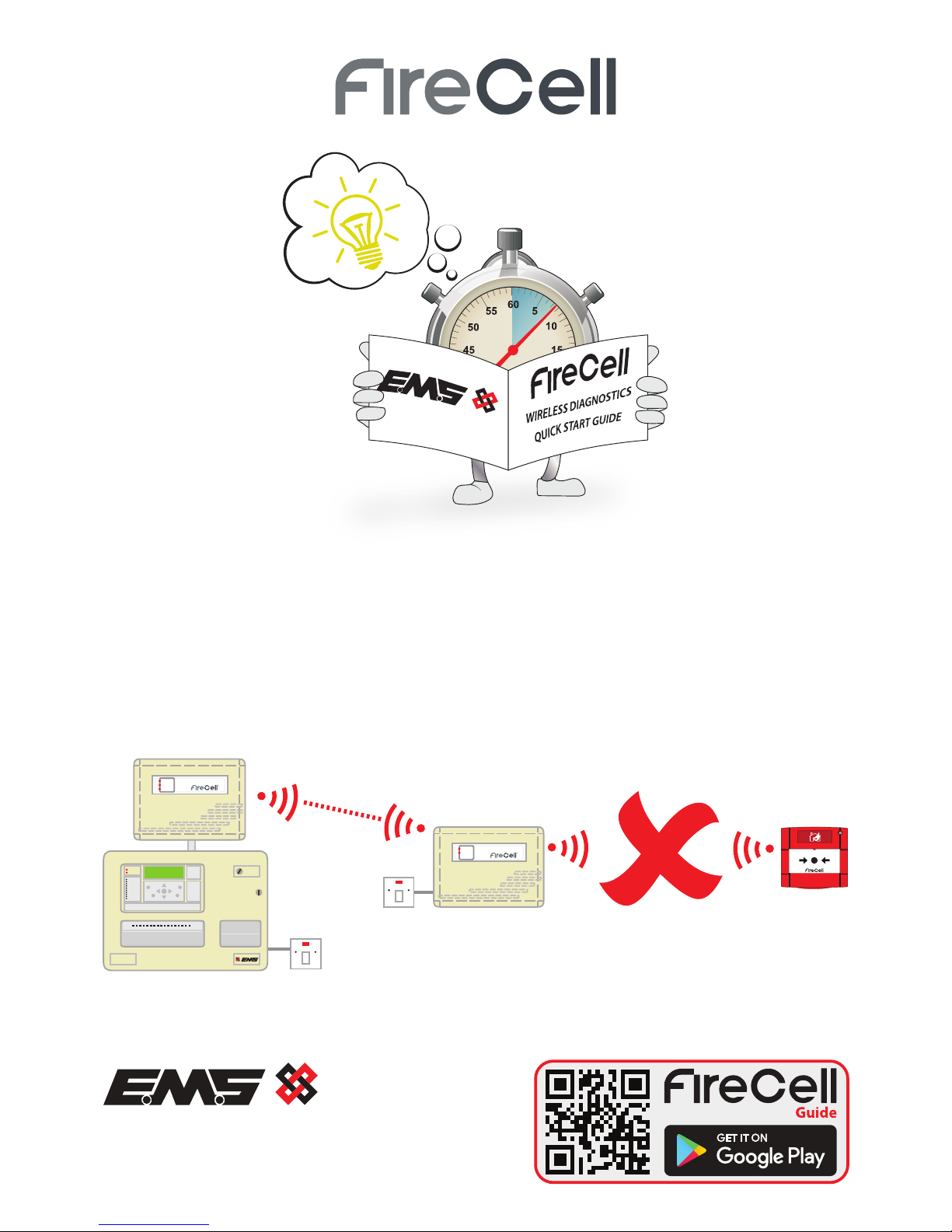
WIRELESS DIAGNOSTICS
QUICK START GUIDE
Page 2
How to resolve a disconnect fault
A device disconnect fault is shown on the Control Panel display, if the communication
path between the individual device and it’s associated Radio Cluster Communicator is
not present. The majority of device disconnect faults can be investigated and resolved
by following these 10 simple steps:
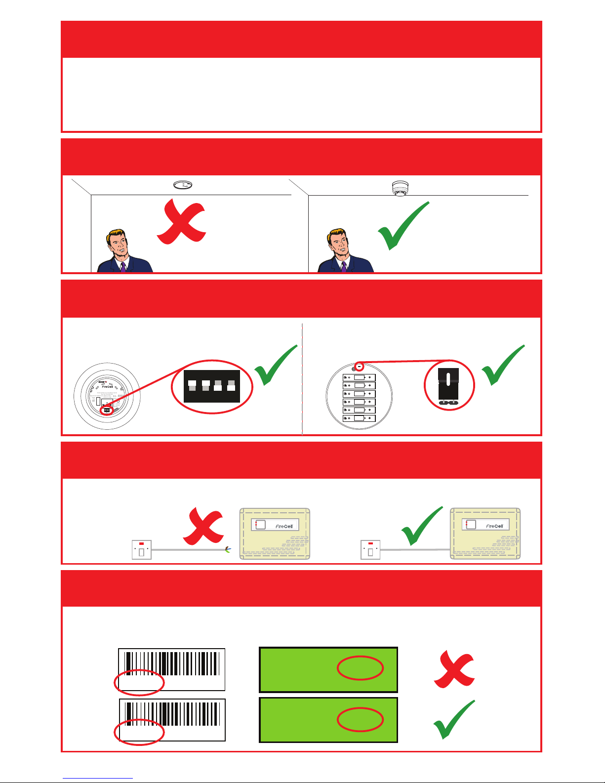
Step 1 Is the device in it’s location?
www.emsgroup.co.uk
Radio Detector Base
PRESS HERE TO
LOG ON
IDENT
Step 2 Is the device powered?
Combined Sounder Detectors are
powered by Switch 1 as shown:
www.emsgroup.co.uk
Combined Sounder
and Detector Base
PRESS HERE TO
LOG ON
IDENT
!
ON
1
234
ON
OFF
0359
12
0359-CPR-00XX
3.5 - 4.5V DC
0.2 - 300mA
1W Max
Type A: for indoor use
Technical Data see Installation Guide
Part No: FCX-XXX-XXX
EN54-3: 2001
EN54-25: 2008
ON
1
2
3
4
Step 3 Is the associated RCC powered?
If not, all devices reporting to the RCC will be disconnected.
POWER
FAULT
Disconnected
230Vac
POWER
FAULT
Connected
230Vac
Other wireless devices have power
jumpers as shown:-
SIZE AA
SIZE AA
SIZE AA
SIZE AA
SIZE AA
SIZE AA
(Link pins to power device)
Step 4 Is the ident programmed correctly?
(Switch 1 On = Power ON)
Check the device’s ident located on the side of the device under the barcode and cross
reference it with the ident programmed into the Radio Hub.
0C03B Rev:5 01/08/17
0C03B Rev:5 01/08/17
RCC01 ID 1C03B
RCC01 ID 0C03B
©2018 EMS Ltd. All rights reserved Page 2 of 4 MK252 Iss 3 15/08/2018 AJM
Page 3

If not try moving the device to the correct/closest RCC. Details can be found within the
FireCell Programming Manual (MK98).
If there is no other RCC to add the device to; an additional RCC may be required, or the
device may require relocation to achieve a better signal.
Step 5 Is the device allocated to the correct RCC?
Step 6 Is the RCC installed as per the survey?
Control Panel
Radio Hub
RCC1
RCC2
Control Panel
Radio Hub
RCC1
RCC2
The recommended distance between metal objects from the aerial is 600mm. The
recommended distance to any other electrical equipment is 2 metres.
POWER
FAULT
POWER
FAULT
600mm AWAY FROM METAL*
2m AWAY
FROM OTHER
ELECTRICAL
EQUIPMENT
2m AWAY
FROM OTHER
ELECTRICAL
EQUIPMENT
2m AWAY
FROM OTHER
ELECTRICAL
EQUIPMENT
*300mm is an acceptable
distance where 600mm is
not achievable
Step 7 Could anything be blocking the signal?
POWER
FAULT
POWER
FAULT
©2018 EMS Ltd. All rights reserved Page 3 of 4 MK252 Iss 3 15/08/2018 AJM
Page 4

Step 8 Has a wireless survey been carried out?
POWER
FAULT
Step 9 Check the device signal strength:
Whilst trying to improve wireless communication, it is important that signal levels are
checked to ensure they are adequate. The devices bi-directional signal information is
displayed in the ‘Signal level’ menu, found in the Radio Hub:
From front display Device Status Select desired device no Signal Level
Received signal levels should be a minimum of 20dB.
Ch1 D RCC01 016dB
Ch1 D RCC01 028dB
Step 10 Still experiencing problems?
Call EMS Technical Support on +44 (0) 8712 710 804* for expert advice.
*
Calls cost 7p per minute plus your phone company’s access charge.
The information contained within this literature is correct at time of publishing. EMS reserves the right to change any information regarding products as part of its continual development
enhancing new technology and reliability. EMS advises that any product literature issue numbers are checked with its head oce prior to any formal specication being written.
enquiries@emsgroup.co.uk
www.emsgroup.co.uk
+44 (0) 1227 369570
©2018 EMS Ltd. All rights reserved Page 4 of 4 MK252 Iss 3 15/08/2018 AJM
 Loading...