

Page 1
RESET
Radio Network Communicator (RNC)
Installation Guide
Part No Product Description
©2018 EMS Ltd. All rights reserved Page 1 of 2 TSD055 Iss 7 16/01/2018 AJM
FCX-438-001 Radio Network Communicator
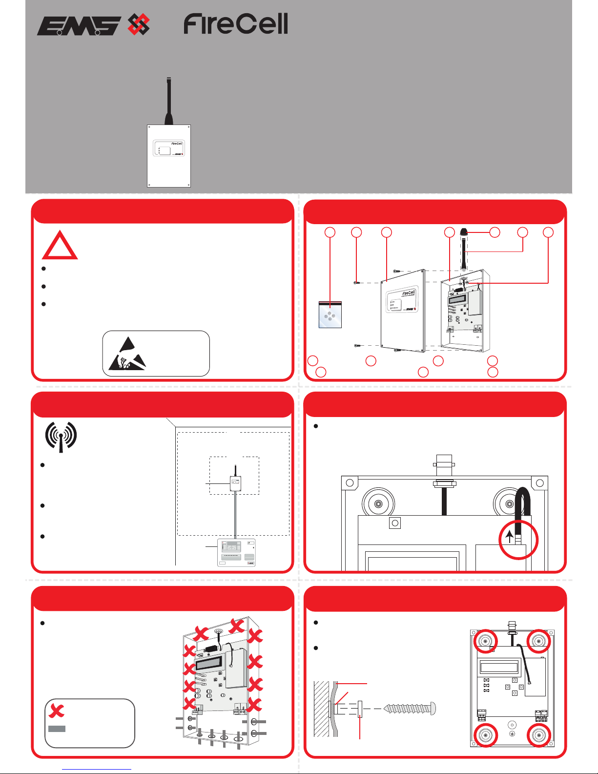
1 Pre Installation 2 Components
6 Fix to the Wall
4 Disconnect Aerial Fly Lead
5 Remove Cable Entry Points
3 Mounting Location Guidelines
!
Installation must conform to applicable local installation
codes and
should only be installed by a fully trained
competent person.
Ensure the RNC is installed as per the site survey.
Refer to step 3 to ensure optimised wireless performance.
If using remote aerials with this product, refer to the Remote
Network Communicator Installation details document (TSD105)
for more information.
ATTENTION
OBSERVE PRECAUTIONS
FOR HANDLING
ELECTROSTATIC
SENSITIVE
Ensure the RNC is not installed
within 2m of other wireless or
electrical equipment (including
the Control Panel)
The RNC’s aerial must not be
installed within 0.6m of any
metal work.
For optimum wireless
performance,the
following must be
observed:
RNCs connected to Syncro AS
panels must also have a high
gain aerial fitted, with the aerial
and RNC separated by 5m.
0.6m
2m
Fire
Panel
RNC
FIRE
Fire Alarm Control
Radio Network Communicator
POWER
NETWORK FAULT
FAULT
Carefully remove the Aerial Fly Lead push on connector,
ensuring excessive strain is not placed on the lead or
connections.
= Do Not Use
= Available Cable
Entry Points
All four circled fixing positions are
available for use.
Radio Network Communicator
POWER
NETWORK FAULT
FAULT
4x Lid Screws 1x RNC Lid 1x RNC Back Box
1x Anti Tamper Shroud 1x RNC Aerial
2
3 4
5 6
2
3 4 5 6
2x Thumb Nuts
7
7
Drill the cable entry points as
necessary.
4x Washers
1
1
NETWORK
FAULT
FAULT
POWER
RESET
UP
ENTER
DOWN
BACK
POWER IN
24Vdc
- +
RS485
IN
+ -
RS485
OUT
+ -
Ensure that the supplied washers
are fitted to all four fixing positions,
as shown below.
Washer (fits over screw insulator)
Pre fitted screw insulator
RNC Back Back Box
Page 2
Page 2 of 2
9 Configuration
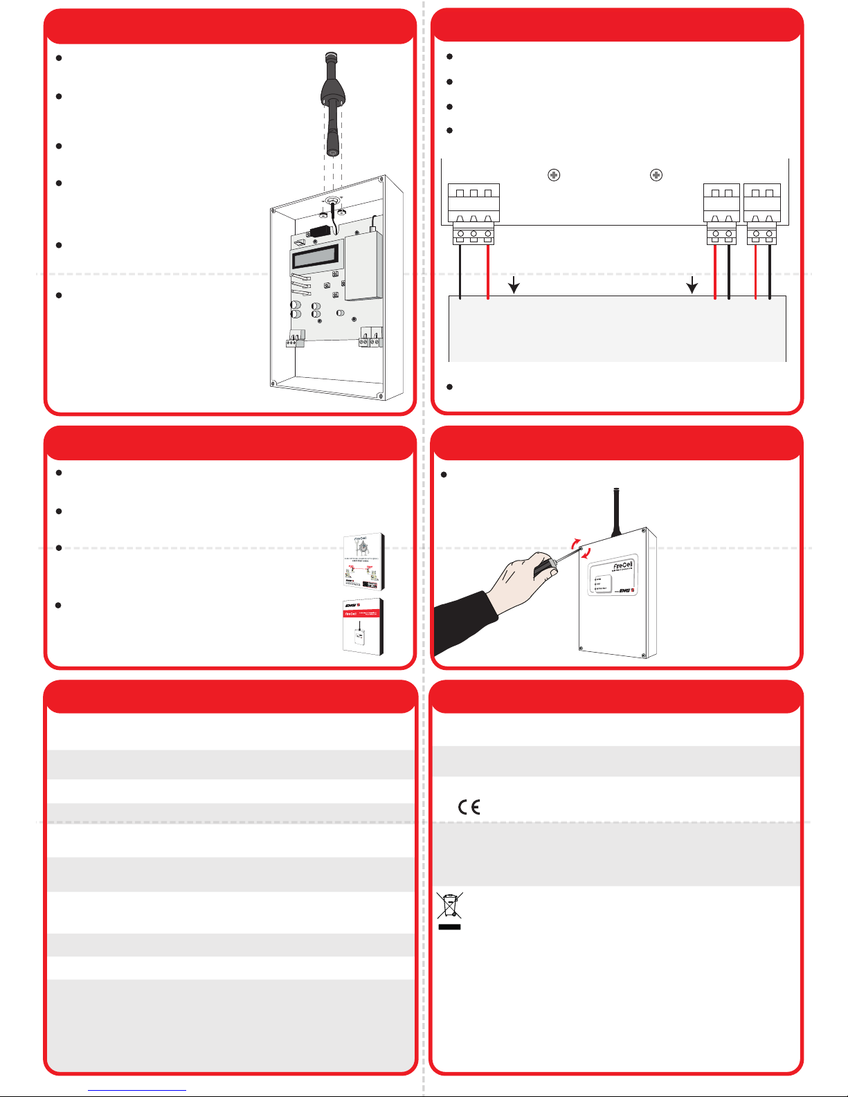
7 Aerial Installation
8 Connection Wiring
Regulatory InformationSpecification
Cables should only be passed via the access points available.
Flame retardant cable glands should be used.
DO NOT leave excess cable in the RNC.
DO NOT earth the enclosure box.
POWER IN
24Vdc
RS485
IN
RS485
OUT
AUX
24Vdc
- +
+ - + -
-
+
NET
OUT
NET
IN
+ -
+ -
To
Control
Panel
To
Control
Panel
Fire Control Panel
Once all connections are made, apply power to the Control
Panel.
Operating
Temperature -10°C to 55°C
Storage
Temperature 5°C to 30°C
Humidity Up to 95% non-condensing
IP Rating IP54
Operating
Voltage 75mA @24Vdc
Operating
Frequency 458MHz
Output
Transmitter
Power 500mW
Dimensions 156mm (W) 228mm (H) 48mm (D)
Weight 0.65kg
Application Indoor Use Only
EN300-220
EN301-489
EN60950
EMS Ltd. Technology House, Herne Bay, Kent,
CT6 8JZ, United Kingdom
Manufacturer
Year of
manufacture See devices serial number label
2012/19/EU (WEEE directive):
Products marked with this symbol cannot be disposed
of as unsorted municipal waste in the European
Union. For proper recycling, return this product to
your local supplier upon purchase of equivalent new
equipment, or dispose of it at designated collection
points.
For more information see www.recyclethis.info
European Union
directives
Hereby, EMS declares that the radio equipment type
FireCell RNC is in compliance with Directive
2014/53/EU. The full text of the EU declaration of
conformity is available at the following internet
address: www.emsgroup.co.uk
Complies with
Programming is only necessary if the RNC, when powered
displays ‘Unprogrammed’.
The RNC’s programming is configured within the menu structure
of the RNC.
If the RNC is displaying a fault, recheck wiring
then refer to the ‘RNC Programming Manual’
(MK137) for full details.
(Free to download from www.emsgroup.co.uk)
Refer to the ‘RNC Quick Start Guide’ (TSD106)
for programming information. These details
can also be found on the RNC lid.
10 Close RNC
Refit the RNC Lid to complete the installation.
Refit the previously removed Aerial Fly
Lead connection.
Fit the Aerial to the BNC connection at
the top of the unit and twist clockwise to
secure into position.
Fit the Aerial Anti-Tamper Shroud over
the aerial.
Secure the shroud, by tightening the
two Thumb Nuts onto the
bottom of the Aerial Shroud as
shown.
Note: If fitting a Remote Aerial
to the RNC, replace the
standard Aerial shown.
Refer to the ‘Radio Network
Communicator Installation
Details sheet’ (TSD105) for
additional information on fitting
remote aerials.
 Loading...