

EMS FireCell FCX-100-101, FireCell FCX-120-101, FireCell FCX-120-111, FireCell FCX-170-101, FireCell 5-RIM Installation Manual
Page 1
www.emsgroup.co.uk
Radio Detector Base
PRESS HERE TO
LOG ON
IDENT
www.emsgroup.co.uk
Radio Detector Base
PRESS HERE TO
LOG ON
IDENT
www.emsgroup.co.uk
Radio Detector Base
PRESS HERE TO
LOG ON
IDENT
63mm
1 Pre Installation
4 Power Device
To unlock, insert a 1.5mm
Allen key into the Allen
key slot and turn
anticlockwise as shown.
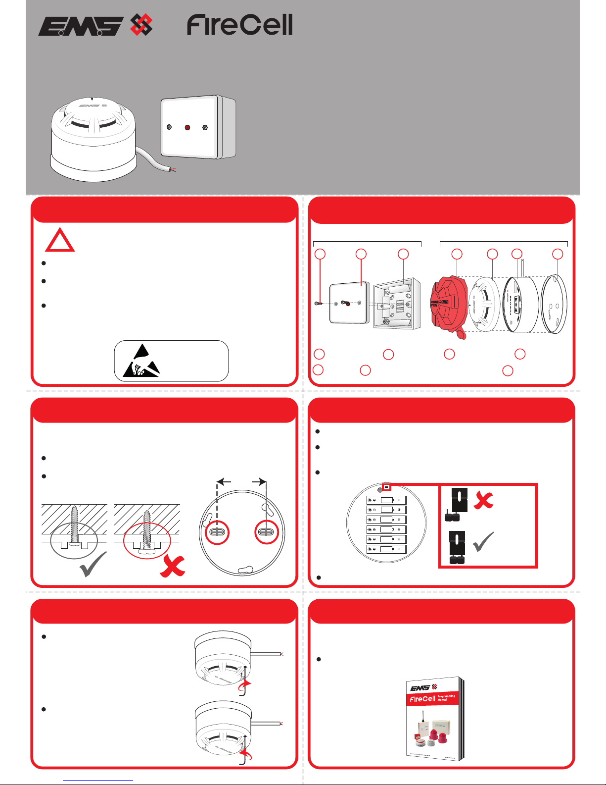
3 Fix Mounting Plate
2 Components
device
unpowered
(pins unlinked)
device
powered
(both pins linked)
!
Installation must conform to applicable local installation
codes and
should only be installed by a fully trained
competent person.
Ensure that the device is installed as per the site survey.
The use of a non-metallic spacer should be considered if
mounting the device on to a metal surface.
Do NOT Press the Log On button on a pre-programmed
device. This will cause communication with the Control Panel
to be lost. Should this happen, delete the device from the
system and add it back on.
Detector
Wireless Module inc 300mm cable
Mounting Plate
Remove the mounting plate from the wireless module, by turning
it anticlockwise.
5 Optional Device Locking
6 Configuration
To lock the detector into
the wireless module,
insert a 1.5mm Allen key
into the allen key slot and
turn clockwise as shown.
Use both mounting holes to ensure a firm fixing.
Use suitable fasteners and fixings.
Once powered, reassemble the device.
The device’s loop address is configured within the menu structure
of the Radio Hub.
Refer to the programming manual (Doc Ref: MK98) for full
programming information.
Free to download from
www.emsgroup.co.uk
Wireless Detector c/w Remote Indicator
Installation Guide
FCX-100-101 Optical Smoke Detector & Remote Indicator Unit
[2][3]
FCX-120-101 Heat A1R Detector c/w Remote Indicator Unit [1][3]
FCX-120-111 Heat CS Detector c/w Remote Indicator Unit [1][3]
FCX-170-101 Wireless Detector Base c/w Remote Indicator Unit [3]
5-RIM Remote Indicator Unit Only
Example shown:
Model FCX-100-101
Part No Product Description
See the Specification section for compliance information.
CPR
SIZE AA
SIZE AA
SIZE AA
SIZE AA
SIZE AA
SIZE AA
ATTENTION
OBSERVE PRECAUTIONS
FOR HANDLING
ELECTROSTATIC
SENSITIVE
5
6
Dust Cover
4
OBSERVE CORRECT POLARITY, USING SPECIFIED BATTERIES.
If fitting / re-fitting batteries; observe correct polarity, using
only specified batteries.
Connect the power jumper across the PIN header.
www.emsgroup.co.uk
Radio Detector Base
PRESS HERE TO
LOG ON
IDENT
2 31 5
6
4 7
Front Cover
Mounting Plate
2
3
7
Fixing Screws
1
Remote Indicator Unit Wireless Detector
©2018 EMS Ltd. All rights reserved Page 1 of 2 TSD033 Iss 3 05/09/2018 AJM
www.emsgroup.co.uk
Radio Detector Base
PRESS HERE TO
LOG ON
IDENT
Page 2
Closed Electrical
Connector
www.emsgroup.co.uk
IDENT
Operating
Temperature -10°C to 55°C
Storage
Temperature 5°C to 30°C
Humidity Up to 95% non-condensing
Supply 6x AA Alkaline (Panasonic LR6AD Powerline /
Varta 4006 Industrial)
CAUTION!
Fitting of an incorrect battery type invalidates the product certification and
may result in poor performance.
IP Rating IP23
Operating
Frequency 868MHz
Output
Transmitter
Power Auto adjusting 0 - 14 dB (0 - 25 mW)
Dimensions (mm) 85(H) x 85(W) x 45(D) (Remote Indicator Unit)
113 (Ø) 81 (D) (Wireless Detector)
Weight 0.15kg (Remote Indicator Unit)
0.40kg (Wireless Detector)
Location Type A: For indoor use
2012/19/EU (WEEE directive):
Products marked with this symbol cannot be
disposed of as unsorted municipal waste in the
European Union. For proper recycling, return this
product to your local supplier upon purchase of
equivalent new equipment, or dispose of it at
designated collection points. For more information
see www.recyclethis.info
Dispose of your batteries in an environmentally
friendly manner according to your local
regulations.
European Union
directives
EMS declares that the radio equipment type FireCell
Detector c/w Remote Indicator is in compliance with
Directive 2014/53/EU. The full text of the EU
declaration of conformity is available at the
following internet address:
www.emsgroup.co.uk
Certification
Certification body
CPR Certificate See part listing for associated products:
DOP [1]0359-CPR-0015, [2]0359-CPR-0017 &
[3]0359-CPR-0041
0359
10
IMPORTANT
Remove dust cover before use.
The device should be tested upon installation and in accordance
with local requirements.
Testing should only be carried out by a fully trained competent
person.
The Manufacturer recommends regular functional testing of at
least once per annum or in accordance with local codes of
practice.
Cleaning and repairs must be undertaken by the Manufacturers
authorised representative.
Do not open the case to clean inside the detector.
!
Specification
See part listing for associated products:
EN54-5:2001. Incorporating Amendment No. 1.
Fire detection and fire alarm systems.
Part 5: Heat detectors - Point Detectors. [1]
EN54-7:2001. Incorporating Amendment No. 1. Fire
detection and fire alarm systems.
Part 7: Smoke detectors - Point detectors using
scattered light, transmitted light or ionization. [2]
E
N54-25:2008.Incorporating corrigenda September
2010 and March 2012. Fire detection and fire alarm
systems.
Part 25: Components using radio links. [3]
Approved to
Regulatory Information
Manufacturer EMS Ltd. Technology House, Herne Bay, Kent,
CT6 8JZ, United Kingdom
Year of
manufacture See devices serial number label
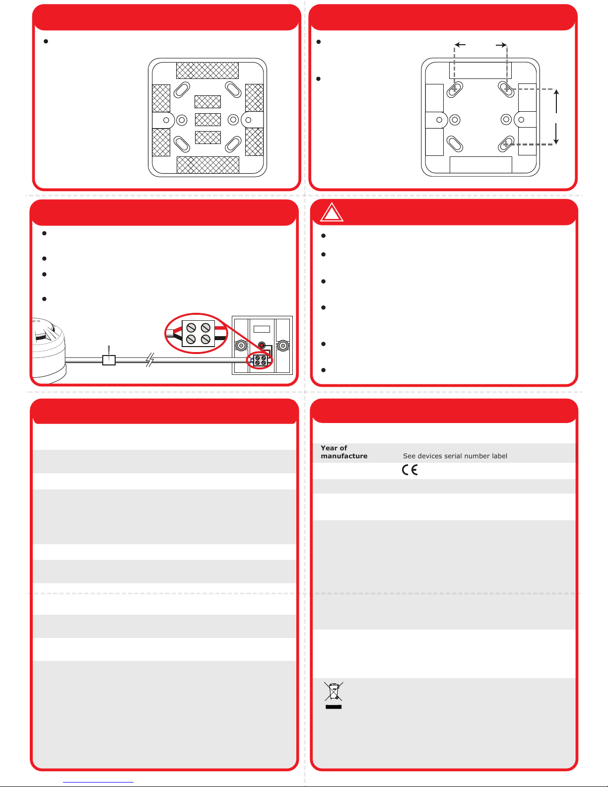
Only use knockouts
shown in shaded
areas.
7 Remove Cable Entry Points 8 Fix to the Wall
40mm
40mm
Use all four mounting
holes.
Use suitable fasteners
and fixings.
9 Wiring
Connect using the two way + and - terminals, observing
correct polarity.
Pass the cable through the premade entry points.
Cabling can be extended up to 30m if required, using a closed
electrical connector.
A maximum of one detector is to be fitted to the Remote
Indicator
©2018 EMS Ltd. All rights reserved Page 2 of 2 TSD033 Iss 3 05/09/2018 AJM
 Loading...