

Page 1
©2018 EMS Ltd. All rights reserved. MK144 (Iss 3) 30/10/2018 AJM
FC-868-SE2
Survey Kit User Guide
Page 2

©2018 EMS Ltd. All rights reserved. Page 2 of 24 MK144 (Iss 3) 30/10/2018 AJM
Contents
Start 3
Introduction 4
About The Survey Kit 5
Survey Kit Overview 6
Signal Surveyor Features 7
Using the Signal Surveyor 7
Signal Surveyor Battery Replacement 8
Device Survey Tool Features 8
Device Survey Tool Battery Replacement 8
Using the Device Survey Tool 9
Survey Results Explained 9
Fusion RLM Survey 10
Fusion RLM Survey Objectives 11
Typical Fusion RLM System Overview 11
Fusion RLM Survey Guidelines 11-13
Step By Step Guide - Fusion System Survey 14
Fusion RLM Survey Form 15
FireCell Survey 16
FireCell Survey Objectives 17
Typical FireCell System Overview 17
FireCell System Survey Guidelines 17-18
Step By Step Guide - FireCell Hub/RCC to RCC Surveying 19
FireCell Hub/RCC to RCC Survey Form 20-21
Step By Step Guide - FireCell Device to RCC Surveying 22
FireCell Device to RCC Survey Form 23
Page 3

©2018 EMS Ltd. All rights reserved. Page 3 of 24 MK144 (Iss 3) 30/10/2018 AJM
Start
Page 4
©2018 EMS Ltd. All rights reserved. Page 4 of 24 MK144 (Iss 3) 30/10/2018 AJM
Introduction
This manual provides a guide to using the FireCell 868MHz wireless survey kit.
The wireless survey kit should be used to determine the FireCell equipment requirements for
the site, to ensure that full wireless site coverage for the areas concerned is achieved, with the
required signal strengths for reliable communication.
Each site will have a level of background noise, that may aect the signals on site. Under
EN54-25 (Fire detection and re alarm systems components using radio links). The minimum
signal headroom must be checked, to ensure reliable communication. This is essential to
ensure immunity against site attenuation, caused by environmental changes and other
electrical equipment.
The survey will create the foot print for the installed system, specifying the nal positions for
the devices and wireless infrastructure.
The FireCell wireless survey kit has been designed so that it can survey both FireCell and
Fusion Radio Loop Module (RLM) systems.
All wireless communication is bi-directional and utilises the 868MHz frequency.
It is recommended that the survey results are recorded for future reference. The survey kit
automatically calculates the required headroom (signal level above background interference),
then displays the results. The results are displayed together with Pass or Fail conrmation.
CH 1 CH 2 CH 1 CH 2
POWER/
CHARGE
TX
RX
RSSI/dB
START
LOCAL - REMOTE REMOTE - LOCAL
SURVEYOR
DEVICE
LOCAL - REMOTE PASS / FAIL
SIGNAL QUALITY %
REMOTE - LOCAL
BATTERY
Page 5

©2018 EMS Ltd. All rights reserved. Page 5 of 24 MK144 (Iss 3) 30/10/2018 AJM
About The Survey Kit
?
Page 6
©2018 EMS Ltd. All rights reserved. Page 6 of 24 MK144 (Iss 3) 30/10/2018 AJM
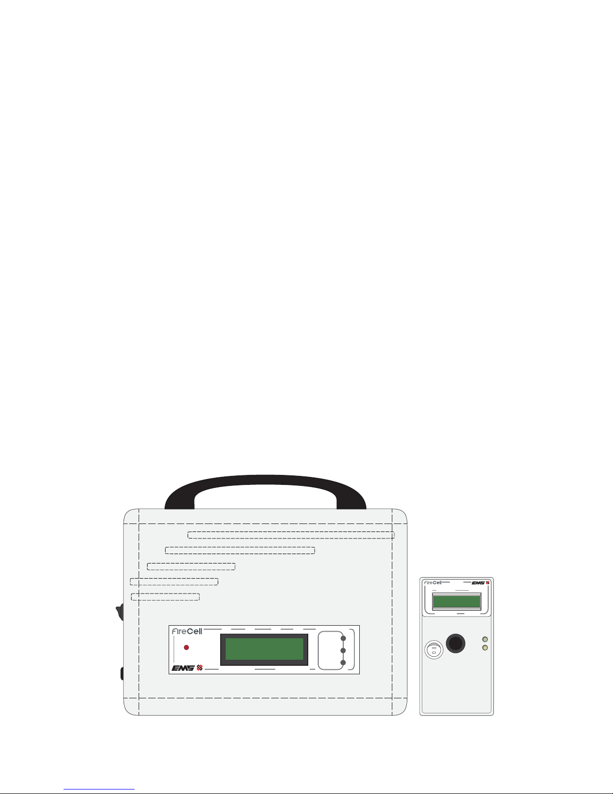
Survey Kit Overview
CH 1 CH 2 CH 1 CH 2
POWER/
CHARGE
TX
RX
RSSI/dB
START
LOCAL - REMOTE REMOTE - LOCAL
Pole Mounted Survey Tool (1 per kit)
This part of the survey equipment when
used in conjunction with the Signal
Surveyor Unit, identies accurate signal
strength information between the two
points. Since wireless devices and RCCs both
communicate using the same 868MHz
wireless protocol, the process for device to
RCC/RLM surveys is the same as RCC to
Hub/RCC surveys.
Signal Surveyor (1 per kit)
This part of the survey equipment is used to
communicate with the Device Survey Tool.
This unit will be located in the position of
the proposed Hub, RCC or RLM.
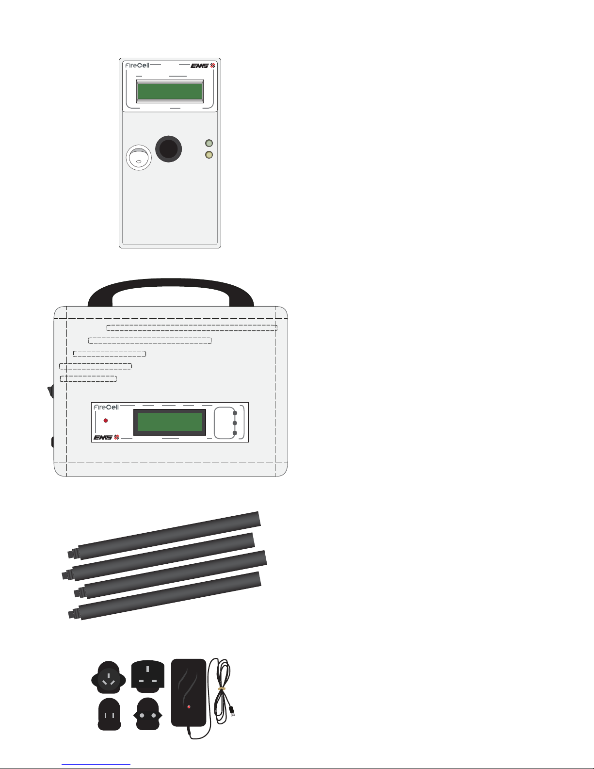
Device Survey Poles (4 per Kit)
The survey poles are used for connection
into the Device Survey Tool. This allows
results to be taken from device locations
which are out of reach.
Note: to ensure optimum surveying accuracy,
it is recommended that minimum two polls
are used with the Survey Tool.
Signal Surveyor mains charger
(provided separately)
The mains charger is used for connection
into the Signal Surveyor units for
re-charging the devices on board battery.
SURVEYOR
DEVICE
LOCAL - REMOTE PASS / FAIL
SIGNAL QUALITY %
REMOTE - LOCAL
BATTERY
Page 7
©2018 EMS Ltd. All rights reserved. Page 7 of 24 MK144 (Iss 3) 30/10/2018 AJM
CH 1 CH 2 CH 1 CH 2
POWER/
CHARGE
TX
RX
RSSI/dB
START
LOCAL - REMOTE REMOTE - LOCAL
018 019 BG RSSI
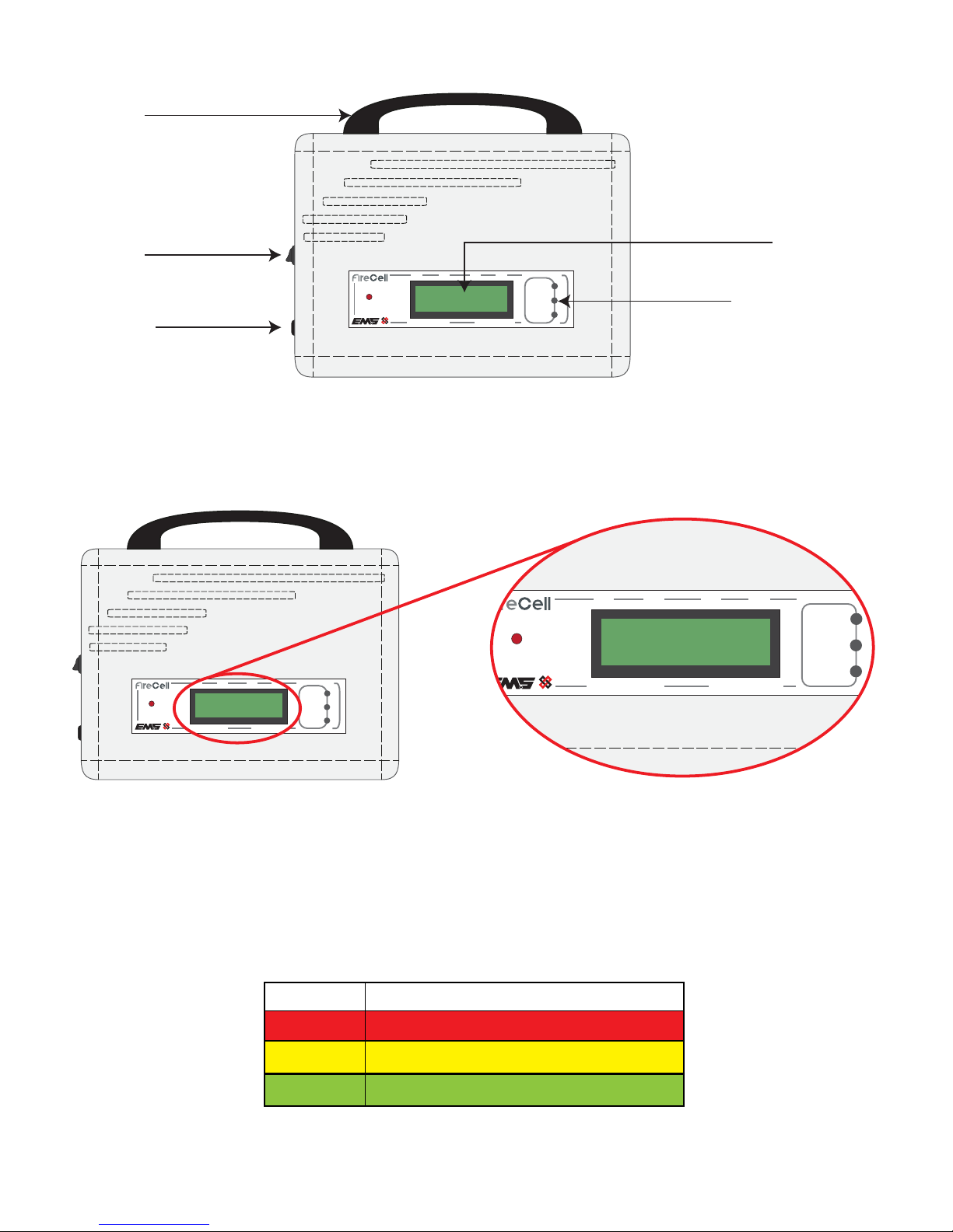
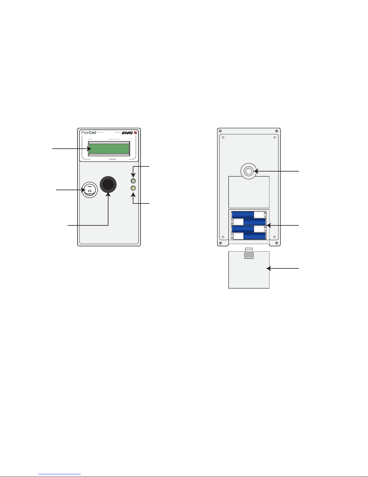
Signal Surveyor Features
Charger
connection
On / O
switch
Carry
handle
LCD display
Power, transmit
and receive LEDs
Using the Signal Surveyor
CH 1 CH 2 CH 1 CH 2
POWER/
CHARGE
TX
RX
RSSI/dB
START
LOCAL - REMOTE REMOTE - LOCAL
018 019 BG RSSI
Once switched on, the Signal Surveyor’s display will show the current background interference
level. To achieve the maximum signal distance the background level should be as low as
possible. This level is shown between 000 and 100. If the background levels are high, try
repositioning the unit. Then turn o and back on again. This will re-show the background level
for the new position.
CH 1 CH 2 CH 1 CH 2
POWER/
CHARGE
TX
RX
RSSI/dB
START
LOCAL - REMOTE REMOTE - LOCAL
018 019 BG RSSI
BG RSSI Recommendation
21-100 High Level Must Re-position Unit
11-20 Medium Try Re-positioning Unit
0-10 Low Continue with survey
Page 8
©2018 EMS Ltd. All rights reserved. Page 8 of 24 MK144 (Iss 3) 30/10/2018 AJM
SURVEYOR
DEVICE
LOCAL - REMOTE PASS / FAIL
SIGNAL QUALITY %
REMOTE - LOCAL
BATTERY
Setting up comms
Surveyor Vxx.xx
LCD
display
On / O
switch
Survey pole
attachment
Green LED signal
pass indicator
Yellow LED signal
fail indicator
Depress
switch to
initiate test
signal
Battery
compartment
Battery
cover
Device Survey Tool Features
Device Survey Tool Battery Replacement
The device Survey Tool requires 4 x AA (LR6 Alkaline 1.5V) batteries. Please ensure batteries are
installed in the correct polarity as shown above.
Signal Surveyor Battery Replacement
The Signal Surveyor’s mains charger can be left connected if necessary, during the survey
process. The rated mains supply voltage is between 90-264Vac 47-63Hz 0.35A max.
Authorised chargers limit output current to 1.0A
Should the internal battery require replacement, correct polarity must be observed as marked
on the battery (NP4-6 6V, 4.0Ah) red wire = positive, black wire = negative.
Page 9

©2018 EMS Ltd. All rights reserved. Page 9 of 24 MK144 (Iss 3) 30/10/2018 AJM
Whether undertaking a Fusion RLM or FireCell survey, a level of 24dB or above is required
as a pass result.
>45dB >45dB Pass
BG = 0dB
>45dB >45dB Pass
100% 98% 0001
Incoming
signal level
in dB
Background
Level in dB
Outgoing
signal
level in dB
Pass / Fail
result
Surveyor
Battery
level
Device
Battery
level
Number of
tests
conducted
Alternating to
Incoming
signal
success rate
Outgoing
signal
success rate
Using the Device Survey Tool
SURVEYOR
DEVICE
LOCAL - REMOTE PASS / FAIL
SIGNAL QUALITY %
REMOTE - LOCAL
BATTERY
>45dB >45dB Pass
BG = 0dB
SURVEYOR
DEVICE
LOCAL - REMOTE PASS / FAIL
SIGNAL QUALITY %
REMOTE - LOCAL
BATTERY
>45dB >45dB Pass
BG = 0dB
With the Device Survey Tool switched on, depress the rear switch to initiate a signal. After a few
seconds results will be displayed and a high pass or a at fail tone will be heard.
LED signal indication is also shown on the device, a Green LED indicates a Pass and the Yellow
LED indicates a Fail.
Note; the battery icons shown above (bottom right of
display), will alternate with a test number also shown.
The background levels are taken into account prior to displaying the events on the units. If the
required device position fails to pass the test then a further RLM/RCC position will need to be
found closer to the device and the survey repeated. Every device position should be recorded
along with the received signal levels.
Survey Results Explained
The gures shown are explained as follows:-
>21dB >21dB Fail
BG = 7dB
>45dB >45dB Pass
BG = 0dB
Page 10

©2018 EMS Ltd. All rights reserved. Page 10 of 24 MK144 (Iss 3) 30/10/2018 AJM
RLM Survey
Page 11
©2018 EMS Ltd. All rights reserved. Page 11 of 24 MK144 (Iss 3) 30/10/2018 AJM
Fusion RLM Survey Guidelines
Before you start surveying the premises there are a number of points to take into consideration
that will aid the survey. These are as follows:-
1. Identify where the RLM is to be installed on the loop cabling. This is the starting point of the
wireless infrastructure and where you should position your Signal Surveyor.
Typical Fusion RLM System Overview
POWER
FAULT
ISOLATOR
ACTIVE
Loop Module
FIRE
Fire Alarm Control
31 Devices per RLM31 Devices per RLM
www.emsgroup.co.uk
Radio Detector Base
PRESS HERE TO
LOG ON
IDENT
www.emsgroup.co.uk
Radio Detector Base
PRESS HERE TO
LOG ON
IDENT
POWER
FAULT
ISOLATOR
ACTIVE
Loop Module
FIRE
Fire Alarm Control
POWER
FAULT
ISOLATOR
ACTIVE
Loop Module
Fusion RLM Survey Objectives
Identify all Fusion RLM positions.
Prove all wireless device communications are above 24dB and indicate a pass.
Page 12

©2018 EMS Ltd. All rights reserved. Page 12 of 24 MK144 (Iss 3) 30/10/2018 AJM
3. Remember to achieve maximum signal range, the RLM should be installed 600mm away from
metal objects and other equipment and 2 metres from electrical equipment. This allows free
space around the RLM’s internal aerials.
600mm AWAY
FROM METAL *
2m AWAY FROM
OTHER ELECTRICAL
EQUIPMENT
2m AWAY FROM
OTHER ELECTRICAL
EQUIPMENT
2m AWAY FROM
OTHER ELECTRICAL
EQUIPMENT
2. Remember when choosing a location, the RLMs require a loop in and out cable connection
and a maximum of ve RLMs per loop are allowed.
Max 5 RLMs
per loop
POWER
FAULT
ISOLATOR
ACTIVE
Loop Module
POWER
FAULT
ISOLATOR
ACTIVE
Loop Module
POWER
FAULT
ISOLATOR
ACTIVE
Loop Module
POWER
FAULT
ISOLATOR
ACTIVE
Loop Module
POWER
FAULT
ISOLATOR
ACTIVE
Loop Module
FIRE
Fire Alarm Control
FIRE
Fire Alarm Control
POWER
FAULT
ISOLATOR
ACTIVE
Loop Module
POWER
FAULT
ISOLATOR
ACTIVE
Loop Module
POWER
FAULT
ISOLATOR
ACTIVE
Loop Module
POWER
FAULT
ISOLATOR
ACTIVE
Loop Module
!
Page 13

©2018 EMS Ltd. All rights reserved. Page 13 of 24 MK144 (Iss 3) 30/10/2018 AJM
POWER
FAULT
ISOLATOR
ACTIVE
Loop Module
RLM
Position
4. Consider positioning your RLMs centrally, giving as much 360 degree coverage as possible.
5. Remember, the RLMs can each accommodate a maximum of 31 wireless devices.
Max 31 devices
per RLM
www.emsgroup.co.uk
Radio Detector Base
PRESS HERE TO
LOG ON
IDENT
POWER
FAULT
ISOLATOR
ACTIVE
Loop Module
!
Page 14

©2018 EMS Ltd. All rights reserved. Page 14 of 24 MK144 (Iss 3) 30/10/2018 AJM
SURVEYOR
DEVICE
LOCAL - REMOTE
PASS / FAIL
SIGNAL QUALITY %
REMOTE - LOCAL
BATTERY
>31dB >31dB Pass
100% 98% 0001
SURVEYOR
DEVICE
LOCAL - REMOTE PASS / FAIL
SIGNAL QUALITY %
REMOTE - LOCAL
BATTERY
Setting up comms
Surveyor Vxx.xx
CH 1 CH 2 CH 1 CH 2
RSSI/dB
Step By Step Guide - Fusion System Survey
Surveyor
in RLM
position
Step 1.
Position the Signal Surveyor in the proposed RLM location.
Step 2.
Turn on the Signal Surveyor.
Step 3.
Record the background level displayed, for future reference.
Refer to the Using the Signal Surveyor section for more
information.
Step 4.
Turn on the Device Survey Tool.
Step 5.
Position the Device Survey Tool against the wall or ceiling in
the positions of the proposed Wireless device.
Step 6.
Record the signal level.
Step 7.
Repeat Steps 5-6 for all device positions associated with the
RLM position.
Steps
5 to 6
Note: a Fusion RLM Survey Form is supplied on page 15.
CH 1 CH 2 CH 1 CH 2
POWER/
CHARGE
TX
RX
RSSI/dB
START
LOCAL - REMOTE REMOTE - LOCAL
Page 15
©2018 EMS Ltd. All rights reserved. Page 15 of 24 MK144 (Iss 3) 30/10/2018 AJM
POWER/
CHARGE
TX
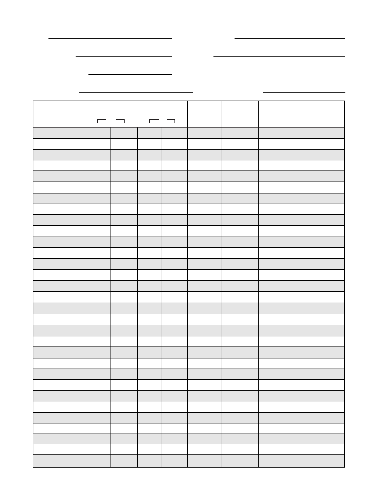
Fusion RLM Survey Form
Site Customer name
Survey date Company
Surveyor name
RLM number Background Level
Device No Signal Level Pass Fail Comments
1
2
3
4
5
6
7
8
9
10
11
12
13
14
15
16
17
18
19
20
21
22
23
24
25
26
27
28
29
30
31
dB %
Page 16
©2018 EMS Ltd. All rights reserved. Page 16 of 24 MK144 (Iss 3) 30/10/2018 AJM
Survey
Page 17
©2018 EMS Ltd. All rights reserved. Page 17 of 24 MK144 (Iss 3) 30/10/2018 AJM
POWER
FAULT
POWER
FAULT
POWER
FAULT
POWER
FAULT
POWER
FAULT
POWER
FAULT
POWER
FAULT
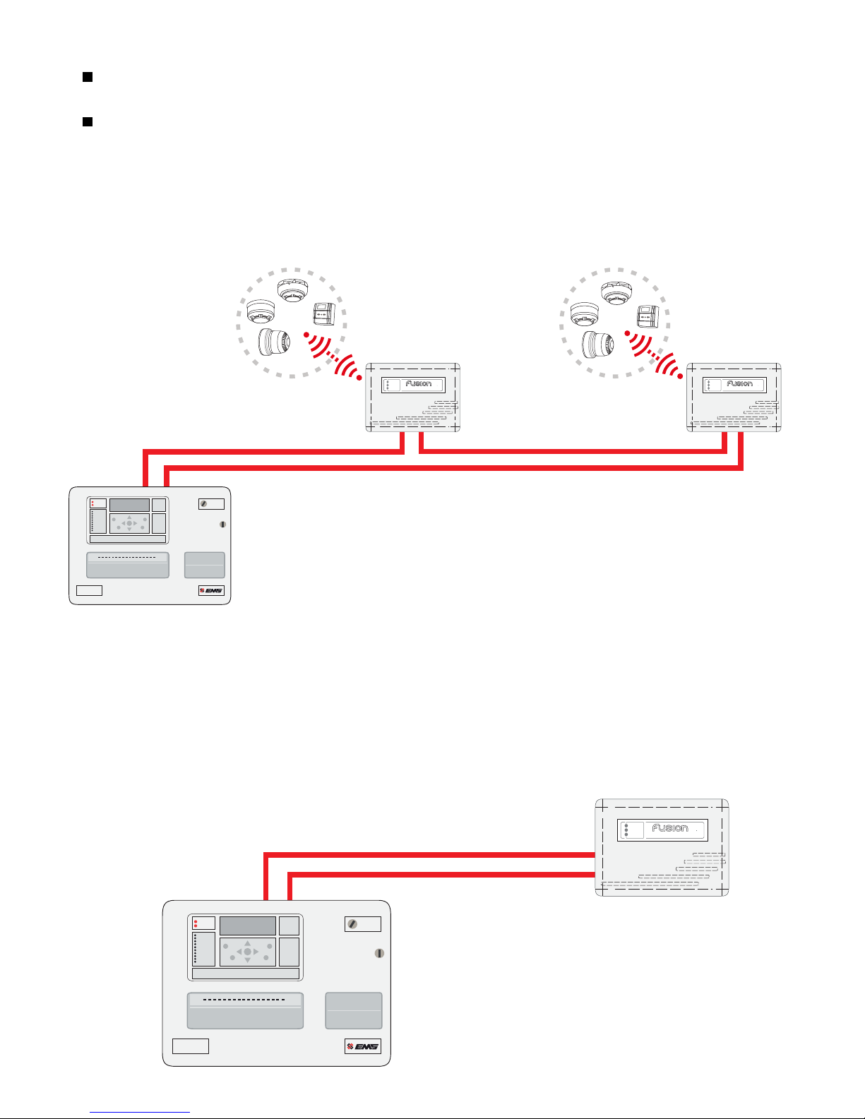
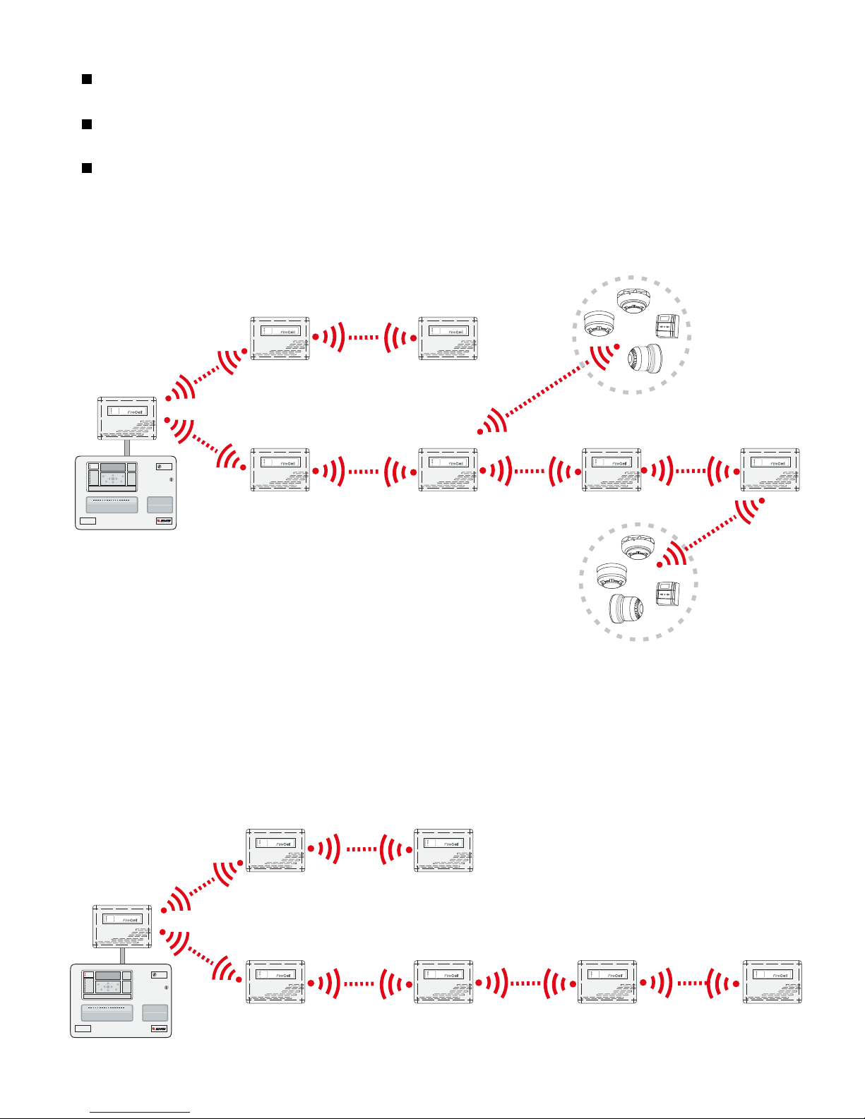
FireCell System Survey Guidelines
Before you start surveying the premises there are a number of points to take into consideration
that will aid the survey. These are as follows:-
1. The Radio Hub and all RCCs must have a valid communication path (pass result).
Control Panel
Radio
Hub
RCC 1
RCC 3
RCC 2
RCC 4 RCC 5 RCC 6
Pass
Pass
Pass
Pass Pass Pass
POWER
FAULT
Control
Panel
Radio
Hub
RCC
RCC
RCC
RCC RCC RCC
Hop 1
Hop 1
Hop 2
Hop 2
Hop 3 Hop 4
31 Devices
per RCC
31 Devices per RCC
Typical FireCell System Overview
www.emsgroup.co.uk
Radio Detector Base
PRESS HERE TO
LOG ON
IDENT
www.emsgroup.co.uk
Radio Detector Base
PRESS HERE TO
LOG ON
IDENT
FIRE
Fire Alarm Control
POWER
FAULT
POWER
FAULT
POWER
FAULT
POWER
FAULT
POWER
FAULT
POWER
FAULT
FIRE
Fire Alarm Control
FireCell Survey Objectives
Identify Hub and all RCC positions.
Prove all Hub/RCC wireless communications are above 24dB and indicate a pass.
Prove all wireless device communications are above 24dB and indicate a pass.
Page 18
©2018 EMS Ltd. All rights reserved. Page 18 of 24 MK144 (Iss 3) 30/10/2018 AJM
POWER
FAULT
POWER
FAULT
POWER
FAULT
POWER
FAULT
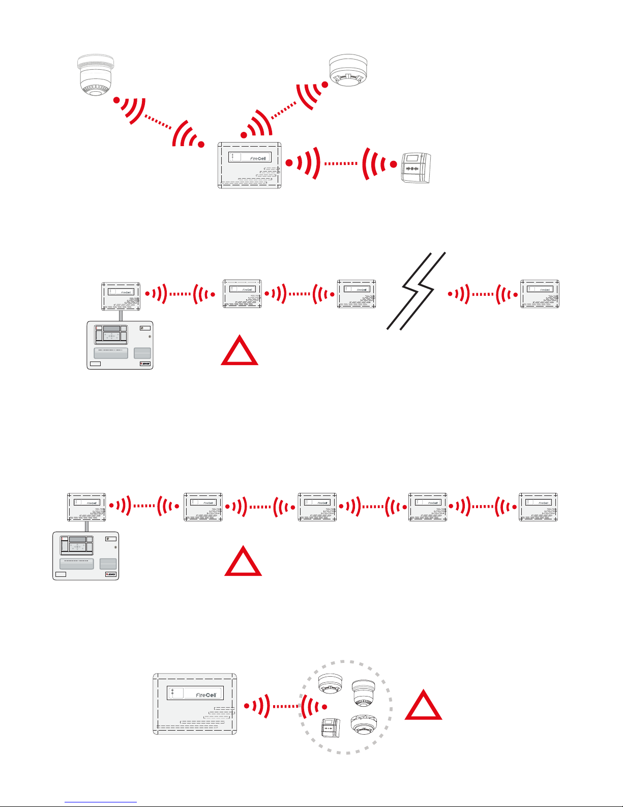
4. A maximum of 4 Hops can be achieved between RCCs to the Hub location.
5. Remember, the RCCs can each accommodate a maximum of 31 wireless devices.
Max 31 devices
per RCC
Control
Panel
Radio
Hub
RCC RCC RCC
RCC
Hop 1 Hop 2 Hop 3 Hop 4
RCC
2. All Devices must have valid communication to an RCC (Pass Result).
www.emsgroup.co.uk
Radio Detector Base
PRESS HERE TO
LOG ON
IDENT
Pass
Pass
Pass
3. Maximum 31 RCCs.
Control
Panel
Radio
Hub
RCC RCC
Pass
RCC
Pass
Max 31 RCCs
RCC
www.emsgroup.co.uk
Radio Detector Base
PRESS HERE TO
LOG ON
IDENT
POWER
FAULT
FIRE
Fire Alarm Control
POWER
FAULT
POWER
FAULT
FIRE
Fire Alarm Control
POWER
FAULT
POWER
FAULT
POWER
FAULT
POWER
FAULT
!
!
Max 4 Hops
!
Page 19

©2018 EMS Ltd. All rights reserved. Page 19 of 24 MK144 (Iss 3) 30/10/2018 AJM
CH 1 CH 2 CH 1 CH 2
RSSI/dB
CH 1 CH 2 CH 1 CH 2
POWER/
CHARGE
TX
RX
RSSI/dB
START
LOCAL - REMOTE REMOTE - LOCAL
Step By Step Guide - FireCell Hub/RCC to RCC Surveying
SURVEYOR
DEVICE
LOCAL - REMOTE
PASS / FAIL
SIGNAL QUALITY %
REMOTE - LOCAL
BATTERY
>31dB >31dB Pass
100% 98% 0001
SURVEYOR
DEVICE
LOCAL - REMOTE PASS / FAIL
SIGNAL QUALITY %
REMOTE - LOCAL
BATTERY
Setting up comms
Surveyor Vxx.xx
Surveyor
in Hub
position
Step 1.
Position the Signal Surveyor in the proposed Radio Hub
location.
Step 2.
Turn on the Signal Surveyor.
Step 3.
Record the background level displayed, for future reference.
Refer to the Using the Signal Surveyor section for more
information.
Step 4.
Turn on the Device Survey Tool.
Step 5.
Position the Device Survey Tool against the wall in the
positions of the proposed RCC position.
Step 6.
Record the signal level.
Step 7.
Repeat Steps 5-6 for all RCC positions as required.
Steps
5 to 6
Note: a Hub/RCC to RCC Survey Form is supplied on page 20.
Note: the Surveyor Unit can be moved to an identied
RCC location to further expand the coverage. Up to
four hops from an RCC to the Hub can be achieved.
!
Page 20
©2018 EMS Ltd. All rights reserved. Page 20 of 24 MK144 (Iss 3) 30/10/2018 AJM
POWER/
CHARGE
TX
FireCell Hub/RCC to RCC Survey Form
Site Customer name
Survey date Company
Surveyor name
Fire Panel and Radio Hub.
Location
EXAMPLE
RCC
Location
Comms Path Talks to: Hub dB % Pass Fail
Signal Level
Background Level
RCC
Location
Comms Path Talks to: dB % Pass Fail
Signal Level
Background Level
31 31 100 98
7 7
Main Corridor
1
RCC
Location
Comms Path Talks to: dB % Pass Fail
Signal Level
Background Level
RCC
Location
Comms Path Talks to: dB % Pass Fail
Signal Level
Background Level
Page 21
©2018 EMS Ltd. All rights reserved. Page 21 of 24 MK144 (Iss 3) 30/10/2018 AJM
RCC
Location
Comms Path Talks to: dB % Pass Fail
Signal Level
Background Level
RCC
Location
Comms Path Talks to: dB % Pass Fail
Signal Level
Background Level
RCC
Location
Comms Path Talks to: dB % Pass Fail
Signal Level
Background Level
RCC
Location
Comms Path Talks to: dB % Pass Fail
Signal Level
Background Level
RCC
Location
Comms Path Talks to: dB % Pass Fail
Signal Level
Background Level
RCC
Location
Comms Path Talks to: dB % Pass Fail
Signal Level
Background Level
Page 22

©2018 EMS Ltd. All rights reserved. Page 22 of 24 MK144 (Iss 3) 30/10/2018 AJM
CH 1 CH 2 CH 1 CH 2
POWER/
CHARGE
TX
RX
RSSI/dB
START
LOCAL - REMOTE REMOTE - LOCAL
SURVEYOR
DEVICE
LOCAL - REMOTE
PASS / FAIL
SIGNAL QUALITY %
REMOTE - LOCAL
BATTERY
>28dB >28dB Pass
99% 99% 0001
Surveyor
in RCC
position
Step 8.
Device to RCC coverage must now be proven. Position the
Signal Surveyor in the proposed RCC location.
Step 9.
Record the background level displayed, for future reference.
Refer to the Using the Signal Surveyor section for more
information.
Step 10.
Position the Device Survey Tool against the wall or ceiling in
the positions of the proposed wireless device.
Step 11.
Record the signal level.
Step 12.
Repeat Steps 10-11 for all device positions associated with the
RCC position.
Step 13.
If there are multiple RCC positions on site, repeat steps 8 to 12
for each RCC.
Steps
8 to 11
CH 1 CH 2 CH 1 CH 2
POWER/
CHARGE
TX
RX
RSSI/dB
START
LOCAL - REMOTE REMOTE - LOCAL
Next RCC
position
Step By Step Guide - FireCell Device to RCC Surveying
Note: a Device to RCC Survey Form is supplied on page 23.
Page 23

©2018 EMS Ltd. All rights reserved. Page 23 of 24 MK144 (Iss 3) 30/10/2018 AJM
FireCell Device to RCC Survey Form
RCC number
Additional notes
Device No Signal Level Pass Fail Comments
1
2
3
4
5
6
7
8
9
10
11
12
13
14
15
16
17
18
19
20
21
22
23
24
25
26
27
28
29
30
31
dB %
Page 24

©2018 EMS Ltd. All rights reserved. Page 24 of 24 MK144 (Iss 3) 30/10/2018 AJM
The information contained within this literature is correct at time of publishing. EMS reserves the right to change any information regarding products as part of its continual development
enhancing new technology and reliability. EMS advises that any product literature issue numbers are checked with its head oce prior to any formal specication being written.
enquiries@emsgroup.co.uk
www.emsgroup.co.uk
+44 (0) 1227 369570
 Loading...