

Page 1
RESET
LOGON
BACK
HEALTHY
FAULT
SYS FAULT
RF1 RF2
EN54-4 UNIVERSAL PSU
FC-60-1000
INPUT: 220-240VAC, 50Hz, 0.3A
OUTPUT: 5.0-8.5VDC, 0.8A MAX
STATUS
FAULT
MAINS / CHARGER FAIL
BATTERY LOW
BATTERY FAIL
START
INPUT
L N E
For additional information refer to TSD042
0359-CPR-00267
15
0359
RESET
LOGONBACK
HEALTHY
FAULT
SYS FAULT
RF1 RF2
UNIVERSAL PSU EMS-PSU-002
INPUT: 220-240VAC, 0.3A
OUTPUT: 5.0-8.5VDC, 1.0A MAX
STATUS
FAULT
MAINS / CHARGER FAIL
BATTERY LOW
BATTERY FAIL
START
INPUT
L N E
14
For additional information refer to
Installation Instructions
0359-CPR-XXXX
0359
230Vac Radio Cluster Communicator (RCC)
Installation Guide
©2015 EMS Security Group Ltd. All rights reserved Page 1 of 2 TSD053 Iss 23 26/07/2017 AJM
FC-555-001
FC-555-331
230Vac RCC c/w PSU
230Vac RCC c/w remote aerial facility & PSU
RADIO CLUSTER COMMUNICATOR
POWER
FAULT
1 Pre Installation
!
Installation must conform to applicable local installation
codes and
should only be installed by a fully trained
competent person.
Ensure the RCC is installed as per the site survey.
Refer to step 3 to ensure optimised wireless performance.
If using remote aerials with this product, refer to the Remote
Aerial Installation guide for more information.
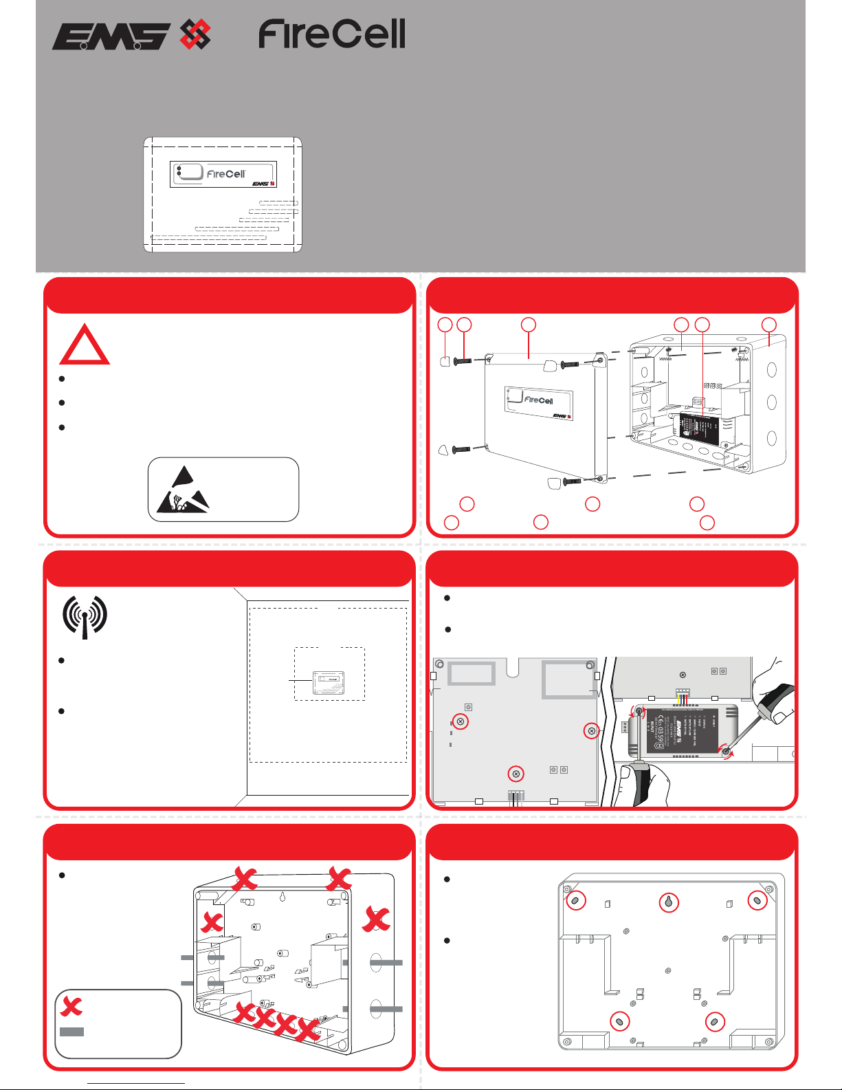
2 Components
Radio Cluster Communicator
POWER
FAULT
1
2
3
6
4
4x Corner Covers 4x Lid Screws 1x RCC Lid
1x RCC PCB 1x RCC Box
3 Mounting Location Guidelines
POWER
FAULT
0.6m
2m
RCC
The RCC must not be installed
within 0.6m of any metal work.
4 Optional PCB / PSU Removal
Remove the three circled retaining screws, prior to unclipping
the PCB.
If removing or rotating the PSU for right hand side mains
entry, remove both PSU retaining screws.
5 Remove Cable Entry Points
Drill the cable entry
points as necessary.
= Do Not Use
= Available Cable
Entry Points
All five circled
fixing positions
are available for
use.
The key hole can
also be used for
locating and
fixing where
required.
6 Fix to the Wall
5
1x RCC Power Supply Unit
Part No Product Description
ATTENTION
OBSERVE PRECAUTIONS
FOR HANDLING
ELECTROSTATIC
SENSITIVE
1
2 3
4
5
6
For optimum wireless
performance,the
following must be
observed:
Ensure the RCC is not installed
within 2m of other wireless or
electrical equipment.
Page 2
Earth wire
Neutral wire
Live wire
RESET
LOGON
BACK
HEALTHY
FAULT
SYS FAULT
RF1 RF2
HEALTHY
FA U LT
SYS FAULT
Operating
Temperature -10°C to 55°C
Storage
Temperature 5°C to 30°C
Humidity Up to 95% non-condensing
IP Rating IP54
Battery Backup 1 x 6V 4Ah Yuasa NP4-6 (sold separately)
For information on routine battery changes, refer to the Universal PSU
instructions (TSD042)
Power Requirements Mains Powered 220-240Vac, 50Hz
Current Consumption 44mA (normal operation)
55.5mA (with mains disconnected)
Battery Standby Time 72 hours*
*Typical 5 year battery life based on normal usage.
Note; if 72 hours battery standby is required, it is recommended that the
battery is replaced every 3 years.
Operating Frequency 868MHz
Output Transmitter
Power Auto adjusting 0 - 14 dBm (0 - 25 mW)
Dimensions 270mm (W) 205mm (H) 75mm (D)
Weight 1.9kg (including battery)
1.15kg (excluding battery)
Location Type A: For indoor use
2012/19/EU (WEEE directive):
Products marked with this symbol cannot be
disposed of as unsorted municipal waste in the
European Union. For proper recycling, return this
product to your local supplier upon purchase of
equivalent new equipment, or dispose of it at
designated collection points. For more information
see www.recyclethis.info
Dispose of your batteries in an environmentally
friendly manner according to your local regulations.
European Union
directives
Hereby, EMS declares that the radio equipment type
FireCell 230Vac RCC is in compliance with Directive
2014/53/EU. The full text of the EU declaration of
conformity is available at the following internet
address: www.emsgroup.co.uk
Approved to
EN54-4:1998 Incorporating Amendments Nos. 1 and
2. Fire detection and fire alarm systems.
Part 4: Power supply equipment.
EN54-18:2005. Fire detection and fire alarm
systems. Part 18: Input/output devices.
EN54-25:2008. Incorporating corrigenda September
2010 and March 2012. Fire detection and fire alarm
systems. Part 25: Components using radio links.
Page 2 of 2
Certification
Certification body
CPR Certificate DOP 0359-CPR-0046
9 Configuration
The RCC’s programming and loop address are configured within
the menu structure of the Radio Hub.
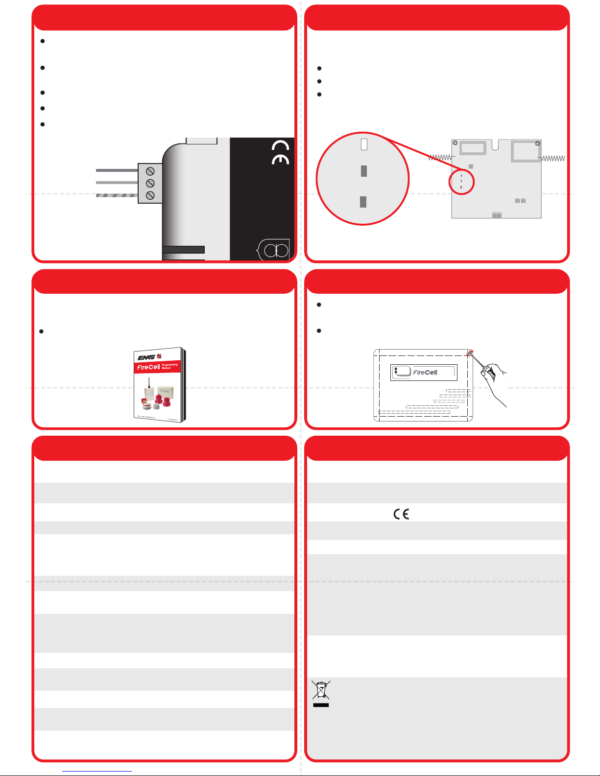
8 Applying Power
Connect the 6V 4Ah battery (sold seperately) and apply power to
the RCC. The normal LED states for the RCC are as below:
10 Close RCC
Healthy LED - Green LED will be on.
Fault LED - Yellow LED will be off.
Sys Fault LED - Yellow LED will be off.
The RCC is powered from a 220-240Vac supply and requires a
5A protection device.
Power cables should only be passed via the access points
available.
Flame retardant cable glands must be used.
DO NOT leave excess cable in the RCC.
Cable should have a minimum cross section of 1.5mm2
RADIO CLUSTER COMMUNICATOR
POWER
FAULT
Refer to the programming manual (Doc Ref: MK98) for full
programming information.
Free to download from
www.emsgroup.co.uk
0359
10
Ensure that the RCC PCB is correctly inserted and the PCB
retaining screws are refitted.
Refit the RCC lid, ensuring LEDs are not damaged by the light
pipe when refitting.
Manufacturer EMS Security Group Ltd. Technology House, Herne
Bay, Kent, CT6 8JZ, United Kingdom
Year of
manufacture See devices serial number label
Regulatory InformationSpecification
EN54-4 UNIVERSAL PSU
FC-60-1000
INPUT: 220-240VAC, 50Hz, 0.3A
OUTPUT: 5.0-8.5VDC, 0.8A MAX
STATUS
FAULT
MAINS / CHARGER FAIL
BATTERY LOW
BATTERY FAIL
START
INPUT
L N E
For additional information refer to TSD042
0359-CPR-00267
15
0359
7 Connection Wiring
 Loading...